manuals.online logo
Brands
  1. Home
  2. •
  3. Brands
  4. •
  5. Panasonic
  6. •
  7. Amplifier
  8. •
  9. Panasonic FX-551 Series User manual

Panasonic FX-551 Series User manual

INSTRUCTION MANUAL
Digital Fiber Sensor Amplier FX-551 Series
ME-FX551 No.0058-72V
Thank you very much for purchasing Panasonic products.
Please read this Instruction Manual carefully and thoroughly for the correct and optimum
use of this product.
Kindly keep this manual in a convenient place for quick reference.
WARNING
●Never use this product as a sensing device for personnel protection.
●In case of using sensing devices for personnel protection, use products which
meet laws and standards, such as OSHA, ANSI or IEC etc., for personnel
protection applicable in each region or country.
This product is not equipped with an automatic interference prevention function.
By setting different frequencies, interference can be prevented for up to four units.
For the setting method, refer to <PRO3> in “
12
PRO MODE.”
1INTENDED PRODUCTS FOR CE MARKING
●This product complies with the following standards / regulations.
<EU Directive>
EMC Directive
2PART DESCRIPTION
UP key
• Teaching
• Threshold value ne
adjustment
• Select setting items
SET key
• Teaching
• Conrm setting
contents
DOWN key
• Teaching
• Threshold value ne
adjustment
• Select setting items
MODE key
• Select modes
• Cancel during setting
Digital display (Green / Red)
MODE indicator: PRO (Yellow)
・Lights when setting PRO mode
MODE indicator: L / D (Yellow)
・Lights when setting SENSING OUTPUT OPERATION MODE
Sensing output operation
indicator (Orange)
MODE indicator: CUST (Yellow)
・Lights when setting LIGHT SENSITIVITY SETTING MODE
<Reference>
Pressing down SET key + MODE key for 3 sec : Set key lock or release key lock
3MOUNTING
How to mount
1. Fit the rear part of the mounting section of
the amplier on a DIN rail.
2. Press down the rear part of the mounting
section of the unit on the DIN rail and t the
front part of the mounting section to the DIN
rail.
2. Press down
1. Fit
35mm width DIN rail
How to remove
1. Push the amplier forward.
2.
Lift up the front part of the amplier to remove
it.
2. Lift up
1. Push forward
How to connect the ber cable
● Mount the ber cables in the state power is not supplied.
●Be sure to t the attachment to the bers rst before inserting the bers to the
amplier. For details, refer to the instruction manual enclosed with the bers.
● Insert the ber cables slowly into the inlets until they stops. Excessive force may
damage the product.
1. Snap the fiber lock lever down till it stops
completely.
2. Insert the ber cables slowly into the inlets
until they stops. (Note)
3. Return the fiber lock lever to the original
position till it stops.
1. Snap
2. Insert
3. Return
Fiber for receiver
Fiber lock lever
Fiber for emitter
Note: With the coaxial reective type ber, insert the single core ber cable into the beam-emitting inlet “P” and the
multi-core ber cable into the beam-receiving inlet.
If they are inserted in reverse, the sensing performance will deteriorate.
4
INSTALL MORE AMPLIFIER OF SERIES CONNECTION TYPE
(Connection type only)
●Make sure that the power supply is OFF while adding or removing the series
connection type.
●This product is not equipped with an automatic interference prevention function.
By setting different frequencies, interference can be prevented for up to four
units. For the setting method, refer to <PRO3> in “
12
PRO MODE.”
●In case 2 or more the series connection types are connected in cascade, make
sure to mount them on a DIN rail.
●In case installing additional amplifier of series connection type, the maximum
15 the series connection types using sub cables (optional) can be added to an
amplier using a main connection cable. (optional)
●When connecting 2 or more the series connection types in cascade, use the sub
cable (optional) for the second series connection type onwards.
For mounting and removing the amplier, refer to “ 3MOUNTING.”
How to cascade
1. Mount the ampliers, one by one, on
the DIN rail.
2.
Slide the ampliers next to each other,
and connect the quick-connection
cables.
3. Mount the end plates MS-DIN-E
(optional) at both the ends to hold the
ampliers between their at sides.
4.
Tighten the screws to fix the end
plates.
How to Remove
1. Loosen the screws of the end plates.
2. Remove the end plates.
3. Slide the ampliers and remove them
one by one.
Slide
Slide
Sub cable (Optional)
Main cable (Optional)
End plate
MS-DIN-E (Optional)
End plate
MS-DIN-E (Optional)
5I/O CIRCUIT DIAGRAMS
< NPN output type >
Main circuit
(Brown) +V (Note)
(Black) Sensing output
(Blue) 0V (Note)
+
‒
12 to 24V DC
+10
‒15 %
Load
< PNP output type >
Main circuit
(Brown) +V (Note)
(Black) Sensing output
(Blue) 0V (Note)
+
‒
12 to 24V DC
+10
‒15 %
Load
Note: The quick-connection sub cable does not incorporate +V (brown) and 0V (blue). The power is supplied from the
connector of the main cable.
< FX551□ terminal arrangement >
2
3
1Terminal No. Terminal name
1 +V
2 Sensing output
3 0V
6OPERATION PROCEDURE
The changed settings are not stored if turning the power OFF while setting.
Therefore, conrm the settings by pressing the SET key before turning the power
OFF.
●When turning ON the power, RUN mode is displayed and the digital display shows
the threshold value (green) and the incident light intensity (red).
• Displays threshold value (green) and incident light intensity (red).
• Teaching, threshold value ne adjustment and key lock function can
be set.
• For setting method of each function, refer to “ 7TEACHING MODE,”
“8THRESHOLD VALUE FINE ADJUSTMENT FUNCTION,” or “ 9
KEY LOCK FUNCTION.”
• Select either Light-ON or Dark-ON.
• For the setting, refer to “
10
SENSING OUTPUT OPERATION MODE.”
• The default setting is “ ” (Light-ON).
• Displays light sensitivity setting and enables its setting.
• For detailed information, refer to “
11
LIGHT SENSITIVITY SETTING
MODE.”
• Detailed settings can be set for maximizing the performance of
individual functions.
• For setting items and setting method, refer to “
12
PRO MODE.”
<RUN mode>
<Sensing output operation mode>
<Light sensitivity setting mode>
<PRO mode>
<RUN mode>
8THRESHOLD VALUE FINE ADJUSTMENT FUNCTION
● Set the ne adjustment of threshold value in RUN mode.
Press down
UP / DOWN key
Press down
SET key
Conrmed
Automatically set without pressing down SET
key in approx. 2 sec.
9KEY LOCK FUNCTION
●The key lock function prevents key operations so that the conditions set in each
setting mode are not inadvertently changed.
●If operating key switch after key lock is set, “ ” is indicated on the
digital display.
<Set key lock>
Automatic
Press down SET
+ MODE keys
simultaneously for
3 sec or longer
<Release key lock>
Press down SET
+ MODE keys
simultaneously for
3 sec or longer
,
are displayed
Automatic
10
SENSING OUTPUT OPERATION MODE
●When MODE indicator: L / D (yellow) lights up, sensing output operation can be
set.
Conrmed
Press down
UP / DOWN key
Press down
SET key
Conrmed
11
LIGHT SENSITIVITY SETTING MODE
●When the MODE indicator: CUST (yellow) lights up, light sensitivity setting can be
displayed.
●By pressing down UP key or DOWN key, light sensitivity setting can be changed.
● Press SET key to conrm the setting.
MODE indicator
CUST (Yellow)
UP key
SET key DOWN key
MODE key
Press down UP / DOWN key
Press down
SET key
Conrmed
7TEACHING MODE
Be sure that detection may become unstable depending on the use environment in
teaching if less margin is applied.
●Teaching can be set in RUN mode.
Useful when sensing object can be set
2-point teaching This is basic teaching method.
1 2
<Reective type><Thru-beam type>
1
2
<Mirror reection type>
1
2
Stable sensing is possible
1. Press the SET key in the sensing object present condition.
2. Press the SET key in the sensing object absent condition.
Stable sensing is not possible
Useful when sensing object cannot be set
Limit-teaching This is teaching method in case small object or object in
back ground are existing.
<Common to thru-beam type, mirror reection type and reective type>
or
Stable sensing is possible
1.
Press the SET key in the sensing object present
condition or non sensing object present condition.
2.
Thru-beam type, mirror reflection
type: Threshold level is shifted to
high value (low sensitivity) when UP
key is pressed down, and it is shifted
to low value (high sensitivity) when
DOWN key is pressed down. (Note)
Reflective type: Threshold level is
shifted to high value (low sensitivity)
when DOWN key is pressed down,
and it is shifted to low value (high
sensitivity) when UP key is pressed
down. (Note)
Stable sensing is not possible
Note: The shift value of approx. 15% is an initial value. Display of the shift value can be changed to
percentage [approx. 0 to 999% (unit 1 %)] or incident light intensity [0 to 9999 (unit 1)].
For setting the shift amount, refer to <PRO1> in “
12
PRO MODE.”
Useful when not want to stop production line and to keep the sensing object move
Full-auto teaching This is method to conduct teaching doing sensing
object is moving.
<Common to thru-beam type, mirror reection type and reective type>
Stable sensing is possible
1. Pressing SET key down
2. Run the sensing object on the line and hold down the SET
key.
Stable sensing is not possible
3. “ ” is displayed on the digital display (green) and
when the sensing object passed through, release the SET
key.
Automatic
Pressing
down long
12
PRO MODE
●When MODE indicator: PRO (yellow) lights up, PRO mode can be set.
DOWN (-) key (select)
MODE indicator PRO (Yellow)
MODE key
UP (+) key (select)
SET key (conrm)
Procedure
The changed settings are not stored if turning the power OFF while setting.
Therefore, conrm the settings by pressing the SET key before turning the power
OFF.
Percentage display
Digit display (Note 3)
SET +,
-
Shift amount setting
Lock OFF Lock ON
+,
-
<PRO2> SET SET
Teaching lock
setting
Incident light
intensity
Percentage
display
Peak / bottom
value
+,
-
+,
-
+,
-
SET
Setting items in
digital display setting
<PRO1> 250μs or less 2ms or less
60μs or less
4ms or less
24ms or less
SET SET +,
-
+,
-
+,
-
+,
-
+,
-
Response time
setting (Note 1)
+,
-
+,
-
+,
-
+,
-
+,
-
+,
-
<PRO1>
OFF Conrm
+,
-
<PRO3> SET SET
Display
adjustment setting
Blink Blinks 3 times
SET SET Automatic
Reset setting
<RUN mode>
SET
Emission frequency setting
Different frequency setting
Emission frequency 1
Emission frequency 4
Emission frequency 2
Emission frequency 3
+,
-
+,
-
+,
-
SET +,
-
+,
-
Setting of threshold
tracking cycle
OFF 1 sec.
SETSET
Setting of threshold
value tracking
+,
-
Sensing
output setting OFF ON
SET +,
-
Storage cycle setting
OFF 1 time
SET +,
-
Algorithm setting
(Note 5) Limit teaching Auto teaching
SET +,
-
+,
-
+,
-
+,
-
+,
-
+,
-
+,
-
Turning OFF Turning ON
+,
-
SET
Setting of digital
display turning
Eco OFF Eco ON Full
+,
-
+,
-
+,
-
SET
ECO setting
+,
-
+,
-
No timer
OFF-delay
timer
One-shot
timer
ON-delay
timer
SET +,
-
+,
-
+,
-
+,
-
Timer setting
sec.
1/10ms
ms
+,
-
+,
-
+,
-
Timer range
Timer time
SET SET
When timer is used, set the timer range and timer time. (Note 2)
When peak / bottom value is selected, set the time period hold
setting. (Note 4)
Ambient environment resistance setting
+,
-
Hold OFF Hold ON
Period hold setting SET
+,
-
Notes: 1) Display of incident light intensity depends on the response time.
Response time Incident light intensity
“ ”, “ ” Max. 4,000
“ ” Max. 8,000
“ ”, “ ” Max. 9,999
Notes: 2) When timer is used, set the timer time. The timer time differs depending on the timer range, as shown in
the table below. Set the timer time after setting the timer range. When setting “ ” , “ ” , “ ” ,
“ ” and “ ” , the timer time of the timer range “1/10ms” cannot be carried out.
Timer range Timer time
“ms” Approx. 1 to 9,999ms
“sec.” Approx. 1 to 32 sec.
“1/10ms” Approx. 0.1 to 999.9ms
Notes: 3) When setting the shift value using the digit display, the setting range differs depending on the response time,
as shown in the table below.
Response time Shift value setting range
“ ”, “ ” Max. 4,000
“ ” Max. 8,000
“ ”, “ ” Max. 9,999
Notes: 4) To clear the value, turn off the time period holding function. Turning off the power switch also clears the value.
Notes: 5) When “ ” is set, limit teaching is conducted according to the change in the incident light intensity, and
then the threshold value is reset. Shift direction of the threshold value differs depending on the combination
of sensing output status and sensing output operation, as shown in the table below.
Sensing output
status
Sensing output
operation Shift direction of threshold value
Sensing output ON Light-ON
Limit teaching is conducted for the negative (-) side of the threshold value.
Sensing output ON Dark-ON
Limit teaching is conducted for the positive (+) side of the threshold value.
Sensing output OFF Light-ON
Limit teaching is conducted for the positive (+) side of the threshold value.
Sensing output OFF Dark-ON
Limit teaching is conducted for the negative (-) side of the threshold value.
Item Default
setting Description
PRO1 mode
Response time setting
Set response time.
Timer setting Set timer operation.
Timer range setting Set timer range and timer time.
Shift amount setting Set shift amount of threshold value in limit teaching.
PRO2 mode
Teaching lock setting
Be able to prevent from wrong operation of teaching.
“ ”: Teaching mode is valid
“ ”: Teaching mode is invalid
Digital display
item setting
Incident light intensity can be displayed in percentage or the peak /
bottom value can be displayed on the digital display (red).
Period hold setting
“ ”: Peak / bottom value in the digital display refreshing
condition can be displayed.
“ ”: Peak / bottom value in the hold condition can be
displayed.
Digital display
turning on setting Sets the viewing orientation of the digital display.
ECO setting
Power consumption can be lowered.
“ ”: ECO OFF
“ ”: If any key operation is not carried out for 20 sec. in RUN
mode, the digital display turns OFF.
“ ”: If key operation is not done in 20 sec. or setting the key
lock function in Run mode, all indicators turns OFF.
PRO3 mode
Display adjustment
setting
Incident light intensity can be set to “0.”
When the correction amount is large, “ ” is blinked as the
setting cannot be conducted normally.
“ ”: Display adjustment OFF
“ ”: Incident light intensity is offset (in the negative direction)
to cancel sneaking light.
Reset setting – If setting to “ ” returns to default settings (factory settings).
Emission frequency
setting
“ ”: Interference prevention function is disabled.
“ ”:
Set this when emission frequency is changed and
interference prevention function is used. The maximum
number of sensor heads for adherence mounting is 4 units
when 4 types of emission frequency are set.
“ ”:
Set this to minimize the effect of ambient environment.
When this setting is set, mutual interference prevention
function is disabled.
Response time is as follows when “ ” or “ ” is selected.
Response
time
“ ”
F-1: 0.8ms or less, F-2: 0.9ms or less
F-3: 1.0ms or less, F-4: 1.7ms or less
* Not affected by “ ” setting.
(
Response time setting
)
“ ”
FAST: 120μs or less, STD: 500μs or less
LONG: 4ms or less, U-LG: 8ms or less,
HYPR: 48ms or less (selectable)
Setting of threshold
value tracking
This mode can change the threshold value depending on the cycle
(1 to 9,999 sec.) that is set with the variations of the incident light
intensity. The tracking shift amount is the one which is set at the shift
setting.
Sensing output
setting
Selects whether tracking threshold when the output is OFF or when
the output is ON.
Storage cycle
setting Selects a threshold storage cycle in EEPROM from 1 to 250 times.
Algorithm setting
“ ”: Limit teaching
Threshold value is followed up on the basis of shift
amount.
(recommended when using thru-beam-type ber or mirror-
reection-type ber)
“ ”: Auto teaching
Threshold value is followed up on the basis of each cycle.
(recommended when using reective-type ber)
13
ERROR INDICATION
●In case of errors, attempt the following measures.
Error
indication Description Remedy
EEPROM is broken or reached the end of its working life. Please replace the product.
EEPROM writing error
Load of the sensing output is short-circuited causing an
over-current to ow. Turn OFF the power and check the load.
14
SPECIFICATIONS
Type Connection type Cable type
NPN output PNP output NPN output PNP output
Model No. FX-551 FX-551P FX-551-C2 FX-551P-C2
Supply voltage 12 to 24V DC+10
‒15 % Ripple P-P10% or less
Power consumption
Normal operation: 960mW or less (current consumption 40mA or less at 24V supply voltage)
Eco mode: 680mW or less (current consumption 28mA or less at 24V supply voltage)
Sensing output
< NPN output type >
NPN open-collector transistor
• Maximum sink current: 100mA (Note 1)
• Applied voltage: 30V DC or less
(Between sensing output and 0V)
• Residual voltage: 2V or less (Note 2)
[At 100mA (Note 1) sink current]
< PNP output type >
PNP open-collector transistor
• Maximum source current: 100mA (Note 1)
• Applied voltage: 30V DC or less
(Between sensing output and +V)
• Residual voltage: 2V or less (Note 2)
[At 100mA (Note 1) source current]
Output operation Switchable either Light-ON or Dark-ON
Short-circuit protection
Incorporated
Response time
(Note 3)
FAST: 60μs or less, STD: 250μs or less, LONG: 2ms or less,
U-LG: 4ms or less, HYPR: 24ms or less, Selectable
Interference revention
function
Incorporated
Emission frequency selection method
(Functions at emission frequency 1, 2, 3 or 4)
Protection IP40 (IEC)
Ambient temperature
(Note 4)
-10 to +55°C (when 4 to 7 units are installed: -10 to +50°C, when 8 to 16 units are
installed: -10 to +45°C) (No dew condensation or icing allowed), Storage: -20 to +70°C
Ambient humidity 35 to 85% RH, Storage: 35 to 85% RH
Material
Enclosure: Polycarbonate, Key: Polyacetal, Protective cover: Polycarbonate
Cable (Note 5) 0.2-mm23-core cabtire cable (2 m) provided
Weight (Main body only)
Approx. 15 g Approx. 60 g
Notes: 1) 50mA in the case 5 or more connection-type units are connected in series
2) When 5-m-long one-touch cable (optional) is used with connection-type units
3) Response tisme varies depending on the emission frequency setting. Regarding the response time in the
case “ ” or “ ” is selected, refer to <PRO3> in “
12
PRO MODE.”
4) In the case of connection type: When connected in series.
In the case of cable type: When adherence-mounted.
5) Cable is not provided with the connection-type product. Be sure to use the following cables (optional).
< Connection type >
Cable
Cable length 1m Cable length 2m Cable length 5m
Main cable Sub cable Main cable Sub cable Main cable Sub cable
FX-551□CN-73-C1 CN-71-C1 CN-73-C2 CN-71-C2 CN-73-C5 CN-71-C5
15
CAUTIONS
●This product has been developed / produced for industrial use only.
● Make sure that the power supply is OFF while adding or removing the ampliers.
●Take care that if a voltage exceeding the rated range is applied, or if an AC power
supply is directly connected, the product may get burnt or be damaged.
●Take care that short-circuit of the load or wrong wiring may burn or damage the
product.
●Do not run the wires together with high-voltage lines or power lines, or put them in
the same raceway. This can cause malfunction due to induction.
● The specication may not be satised in a strong magnetic eld.
●Verify that the supply voltage variation is within the rating.
●If power is supplied from a commercial switching regulator, ensure that the frame
ground (F.G.) terminal of the power supply is connected to an actual ground.
●In case noise generating equipment (switching regulator, inverter motor, etc.) is
used in the vicinity of this product, connect the frame ground (F.G.) terminal of the
equipment to an actual ground.
●The ultra long distance (U-LG, HYPR) mode is more likely to be affected by
extraneous noise since the sensitivity of that is higher than the other modes. Make
sure to check the environment before use.
●Do not use during the initial transient time (FAST, STD: 0.5 sec., LONG, U-LG,
HYPR: 1 sec.) after the power supply is switched ON.
●When extending the cable length, use a cable with a conductor cross-sectional
area of 0.3 mm2or more. Note that the maximum allowed cable length is 100 m.
However, in order to reduce noise, make the wiring as short as possible.
●
Set the power supply voltage by considering the voltage drop resulting from the
conduction resistance of the cable.
●Make sure that the cable joint is not applied with stress, such as strain caused by
forcible bending or pulling.
●This product is suitable for indoor use only.
●Avoid dust, dirt, and steam.
●Take care that the product does not come into contact with organic solvents such
as thinner.
●Take care that the product does not come into contact with strong acids or alkalis.
●Take care that the product does not come into contact with oil or grease.
●This product cannot be used in an environment containing inflammable or
explosive gasses.
●Never disassemble or modify the product.
●This product adopts EEPROM. Settings cannot be done 100 thousand times or
more because of the EEPROM’s lifetime.
http://panasonic.net/id/pidsx/global
Overseas Sales Division (Head Ofce)
2431-1 Ushiyama-cho, Kasugai-shi, Aichi, 486-0901, Japan
Phone: +81-568-33-7861 FAX: +81-568-33-8591
For sales network, please visit our website.
PRINTED IN JAPAN © Panasonic Industrial Devices SUNX Co., Ltd. 2017
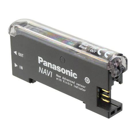
This manual suits for next models

4

Other Panasonic Amplifier manuals

Panasonic LA-A1 User manual

Panasonic

Panasonic LA-A1 User manual

Panasonic RAMSA WP-1200 User manual

Panasonic

Panasonic RAMSA WP-1200 User manual

Panasonic MINAS-BL GU series User manual

Panasonic

Panasonic MINAS-BL GU series User manual

Panasonic FZ-11 User manual

Panasonic

Panasonic FZ-11 User manual

Panasonic CY-M7052 Operating User manual

Panasonic

Panasonic CY-M7052 Operating User manual

Panasonic MINAS-BL GU series Owner's manual

Panasonic

Panasonic MINAS-BL GU series Owner's manual

Panasonic FX-501 User manual

Panasonic

Panasonic FX-501 User manual

Panasonic MJE-FX501 User manual

Panasonic

Panasonic MJE-FX501 User manual

Panasonic CY-PA2003W User manual

Panasonic

Panasonic CY-PA2003W User manual

Panasonic SU-7 Series User manual

Panasonic

Panasonic SU-7 Series User manual

Panasonic CY-PAD1003N User manual

Panasonic

Panasonic CY-PAD1003N User manual

Panasonic WA-H120N User manual

Panasonic

Panasonic WA-H120N User manual

Panasonic FX-502 User manual

Panasonic

Panasonic FX-502 User manual

Panasonic SU-MED640E User manual

Panasonic

Panasonic SU-MED640E User manual

Panasonic MINAS-BL KV Series Owner's manual

Panasonic

Panasonic MINAS-BL KV Series Owner's manual

Panasonic SUC1010 - AMPLIFIER User manual

Panasonic

Panasonic SUC1010 - AMPLIFIER User manual

Panasonic CY-M9054 Operating User manual

Panasonic

Panasonic CY-M9054 Operating User manual

Panasonic FX-502 User manual

Panasonic

Panasonic FX-502 User manual

Panasonic SE-HDV600 User manual

Panasonic

Panasonic SE-HDV600 User manual

Panasonic CYM7002EUC - AUTO POWER AMPLIFIER User manual

Panasonic

Panasonic CYM7002EUC - AUTO POWER AMPLIFIER User manual

Panasonic Minas-LIQI Series Use and care manual

Panasonic

Panasonic Minas-LIQI Series Use and care manual

Panasonic CY-M9054EN User manual

Panasonic

Panasonic CY-M9054EN User manual

Panasonic RAMSA WP-1200B/G User manual

Panasonic

Panasonic RAMSA WP-1200B/G User manual

Panasonic Ramsa WX-RP900 User manual

Panasonic

Panasonic Ramsa WX-RP900 User manual

Popular Amplifier manuals by other brands

zapco ZX-series owner's manual

zapco

zapco ZX-series owner's manual

Musical Fidelity A3.2 Instructions for use

Musical Fidelity

Musical Fidelity A3.2 Instructions for use

Pyle Pro PRAGE75 user manual

Pyle Pro

Pyle Pro PRAGE75 user manual

Audient ASP880 quick start guide

Audient

Audient ASP880 quick start guide

HELIX I58X Operation manual

HELIX

HELIX I58X Operation manual

B&K AV1260 owner's manual

B&K

B&K AV1260 owner's manual

Skye SKP 125 VS manual

Skye

Skye SKP 125 VS manual

Technics SU-V85A - service Service manual

Technics

Technics SU-V85A - service Service manual

Cary Audio Design SA-500.1 owner's manual

Cary Audio Design

Cary Audio Design SA-500.1 owner's manual

Quicksilver Preamplifier operating instructions

Quicksilver

Quicksilver Preamplifier operating instructions

Warwick Pro Tube IV Wiring diagram

Warwick

Warwick Pro Tube IV Wiring diagram

Cool music BP-60D manual

Cool music

Cool music BP-60D manual

Harman Kardon HK775 owner's manual

Harman Kardon

Harman Kardon HK775 owner's manual

Eico HF 86 instruction manual

Eico

Eico HF 86 instruction manual

Moonriver Audio 404 operating instructions

Moonriver Audio

Moonriver Audio 404 operating instructions

Analog Technologies AHVA2KV2X5MA manual

Analog Technologies

Analog Technologies AHVA2KV2X5MA manual

Evh 5150-III Ower's manual

Evh

Evh 5150-III Ower's manual

Irradio IR DA3 TUBE instruction manual

Irradio

Irradio IR DA3 TUBE instruction manual

manuals.online logo
manuals.online logoBrands
  • About & Mission
  • Contact us
  • Privacy Policy
  • Terms and Conditions

Copyright 2025 Manuals.Online. All Rights Reserved.