manuals.online logo
Brands
  1. Home
  2. •
  3. Brands
  4. •
  5. Panasonic
  6. •
  7. Amplifier
  8. •
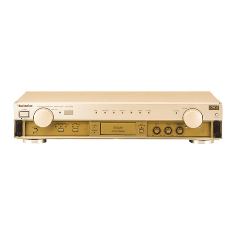
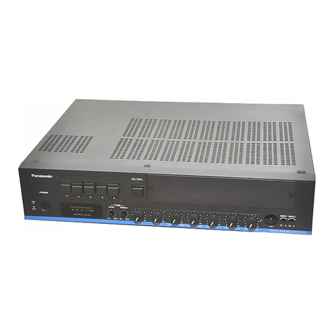
  9. Panasonic SU-CH7 User manual

Panasonic SU-CH7 User manual

ORDER
NO.
AD9104082C8
Service
Manual
Amplifier
enact
Because
of
unique
interconnecting
cables,
when
a
component
requires
service,
send
or
bring
in
the
entire
system.
m@
SPECIFICATIONS
(DIN
45
500)
@
MAIN
AMP.
SECTION
Power
output
DIN
1
KHz
THD
1%
60.
2x25
W
10
kHz
THD
1%
80
2x5
W
both
channel
driven
at
240
V
Total
harmonic
distortion
half
power
at
1
kHz:
Low
Amp
0.09%
(6Q)
Headphones
output
level/impedance
300
mV/330Q
m@
PREAMP.
SECTION
input
sensitivity/impedance
PHONO
3
mV/47
kQ
MIC
0.7
mV/10
kQ
DAT
250
mV/27
kQ
S/N
(rated
power,
6Q):
Low
Amp
PHONO
70
dB
(IHF.
A
75
dB)
DAT,
CD,
TAPE
84
dB
(IHF.
A
85
dB)
Graphic
equalizer
control
80
Hz,
250
Hz,
1
kHz,
4
kHz,
12.5
kHz
Muting
—20
dB
Super
bass
55
Hz,
+44B
Output
voltage/impedance
DAT
REC
OUT
150
mV
(E)
(EB)
(EG)
(GC)
(GN)
CD
Player
System
[Tuner
|
Amplifier
|
SC-CH7
ST-CH7L
SU-CH7
SL-CH7
Technics/Panasonic
|
Amplifier
Color
(K)
ceviv
cee.
Black
Type
Continental
Europe.
Great
Britain.
F.R.
Germany
and
Italy.
Asia,
Latin
America,
Middle
Near
East
and
Africa.
(GN)
Oceania.
System:
SC-CH7
m@
GENERAL
Power
consumption
250
W
Power
supply
For
Great
Britain
and
Oceania
AC
50/60
Hz,.230~240
V
For
F.R.
Germany,
Italy
and
Continental
Europe
AC
50/60
Hz,
230
V
For
others
AC
50/60
Hz,
110
V~127
V/220
V~240
V
Dimensions
(WxHxD)
215
110x303
mm
(815/42"X
41
Yo”
1115/16")
Weight
43
kg
(9.3
Ib.)
Notes:
1.
Total
harmonic
distortion
is
measured
by
the
digital
spectrum
analyzer.
2.
Specifications
are
subject
to
change
without
notice.
3.
Weight
and
dimensions
shown
are
approximate.
Cassette
Deck
Speacers
RS-CH7
SB-¢
H7
SU-CH7
m@
CONTENTS
Page
:
Page
BEFORE
REPAIR...
2...
cee
eee
e
een
eee
2
SCHEMATIC
DIAGRAM
........0
0.0
cece
ence
eee
13~19
PROTECTION
CIRCUITRY
2.0.0...
.
ccc
eee
cece
ence
ee
2
PRINTED
CIRCUIT
BOARDS.
............
0.0.0
cece
eee
20~24
ACCESSORIES?
«5.2
sev.ccntsueSing
euip
ance
Weeks
Mey
eae
as
eles
2
WIRING
CONNECTION
DIAGRAM
.............
00.00
e
cues
25
HOW
TO
INSTALL
THE
SYSTEM.............00.0
0c
cece
ees
3
FUNCTIONS
OF
IC
TERMINALS
.........
0.00.
c
es
ce
eee
sees
26
CONNECTIONS
.......
0.
cece
ence
cece
ene
ene
4,5
BLOCK
DIAGRAM
.........
cece
cece
cents
27~29
LOCATION
OF
CONTROLS
......
00.00
cee
eee
eee
6,7
REPLACEMENT
PARTS
LIST
..........
00.00
cee
e
eee
30~36
DISASSEMBLY
INSTRUCTIONS
...............
0...
eee
ee
8~11
CABINET
PARTS
LOCATION
..............00.0
cece
eae
37,
38
DESCRIPTION
OF
FLPANEL
...............2.
ccc
cence
12
PACKING
(For
System:
SC-CH7).............
0.00
e
cece
vues
39
m@
BEFORE
REPAIR
(1)
Turn
off
the
power
supply.
Using
a
10Q,
5
W
resistor
connect
both
ends
of
power
supply
capacitors
(C703,
C704)
in
order
to
discharge
the
voltage.
(2)
Before
turning
the
power
supply
on,
after
completion
of
repair,
slowly
apply
the
primary
voltage
by
using
a
power
supply
voltage
controller
to
make
sure
that
the
consumed
current
at
50
Hz/60
Hz
in
NO
SIGNAL
mode
should
be
shown
below
with
respect
to
supply
voltage
110
V~127
V/220
V~240
V.
Consumedcurrent50H2
|
———
85~255
mA
x
PROTECTION
CIRCUITRY
The
protection
circuitry
may
have
operated
if
either
of
the
following
conditions
is
noticed:
“No
sound
is
heard
when
the
power
is
switched
ON.
“Sound
stops
during
a
performance.
The
function
of
this
circuitry
is
to
prevent
circuitry
damage
if,
for
example,
the
positive
and
negative
speaker
connection
wires
are
“shorted”,
or
if
speaker
systems
with
an
impedance
less
than
the
indicated
rated
impedance
of
this
unit
are
used.
If
this
occurs,
follow
the
procedure
outlined
below:
:
1.
Switch
OFF
the
power.
2.
Determine
the
cause
of
the
problem
and
correct
it.
3.
Switch
ON
the
power
once
again.
Note:
When
the
protection
circuitry
functions,
the
unit
will
not
operate
unless
the
power
is
first
switched
OFF
and
then
ON
again.
m
ACCESSORIES
Speaker
cords
(2)
<REC201B500-1>
@AC
power
supply
cords
(1)
<SFDACO5E03>
for
(E,
EG)
area
<SJA193>
for
(EB)
area
<RJA0004>
for
(GC)
area
<SJA173>
for
(GN)
area
Remote
control
batteries
(2)
(UM-4,
“AAA”,
R03)
@FM
indoor
antenna
(1)
<SSA270M>
for
(E,
EB,
EG)
area
<SSA272M>
for
(GC,
GN)
area
©)
eAttachment
plug
(1)
<SJP9009>
for
(EB)
area
Remote
control
transmite
r
(1)
<RAK-SC510W>
for
(E,
EB,
EG)
area
<RAK-SC511W>
for
(GC,
GN)
area
SU-CH7
@Flat
cables
(2)
Back
cover
(4)
@LW/MW
loop
antenna
(1)
and
Antenna
holder
(1)
7
and
mounting
screws
(2)
sp
<RYFO122-K>
——SSY]
for
CD
player
Blue
(REX9162)
ay
<RYFOI22K>
SS
for
tuner
<SPB1163T>
Black
(REX9163)
SLD
<RKF0127D-
K2>
for
amplifier
<SMA233-1M>
fs
<RKF0127E-K2>
ey
SS
¥
—
for
cassette
deck
<XTN3+10AFZ>
“
Installing
the
components
vertically
Left
speaker
Right
speaker
SB-CH7
Compact
disc
SB-CH7
player
So
‘2]
SL-CH7
Tuner
eS?
___
900}
ST-CH7L
Amplifier
SU-CH7
Cassette
deck
RS-CH7
J@o
Compact
disc
Tuner
player
ST-CH7L
SL-CH7
°
900
t=
es
°
——~
5}
C)
Ca
OS
o
=0
==]
ane
UES
CYT.
eee
aeme
omen
FW
a
-
-2
Amplifier
Cassette
deck
SU-CH7
RS-CH7
Installing
the
components
on
a
line
Amplifier
Tuner
Cassette
deck;
SU-CH7
ST-CH7L
RS-CH7
Compact
disc
player
SL-CH7
pean
ee
;
;
F
:
i
;
3
SUCH
m
CONNECTIONS
Flat
cables
After
connection,
please
fold
and
press
the
cables
as
flat
to
the
back
of
the
unit
as
possible.
From
the
amplifier
to
the
cassette
deck
Connecting
Hold
the
connector
with
the
recessed
part
up
and
press
Power
switch
is
located
on
the
rear
panel.
in
at
the
center
until
you
hear
Pa)
Make
sure
that
the
power
switch
on
the
back
of
the
a
click.
4
amplifier
is
switched
ON.
The
white
line
should
be
on
the
right
side.
Disconnecting
When
installing
the
back
cover,
put
this
flat
cable
out
of
the
back
cover.
Speaker
cables
Other
types
of
speaker
cannot
be
connected
to
this
unit.
Match
the
four
wires
from
the
left
and
right
speaker
cables
with
the
same
colored
levers
of
the
speaker
terminales,
then
insert
the
wires
into
the
respective
terminals.
@
Twist
the
wire.
@
Push
down
on
the
lever,
insert
the
bare
ends
of
the
wires,
and
push
up
the
lever.
(Refer
to
the
right)
Note:
¢Make
sure
the
bare
ends
of
the
wires
are
not
unraveled.
(If
they
are,
twist
them
tight
again.)
fx
fc
eTake
care
not
to
short
the
wires.
(The
main
unit
could
be
damaged
if
they
are
shorted.)
Speaker
First
connect
the
cables
to
the
speakers,
then
to
the
amplifier.
Speaker
cable
(included)
Speaker
Amplifier
Notice
for
speaker
connections:
Connect
each
color
coded
wire
of
the
speaker
cable
to
the
corresponding
color
coded
terminal
according
to
the
following
chart.
Polarity
l
High
tone
|
[Lowtone
||
Black
External
unit
connection
:
@
DAT
(digital
audio
tape
deck)
DAT
INPUT
OUTPUT
Stereo
pin
cord
Amplifier
[
REC
OUT
PLAY
BACK
et
ee
@
PHONO
(turntable
system)
Turntabl
OUTPUT
seein
Stereo
————_.
i
pin
cord
Amplifier
B
“GND”
terminal
This
terminal
is
for
use
with
turntables
which
have
a
ground
wire.
SU-CH7
m
LOCATION
OF
CONTROLS
Amplifier:
control
section
@
@
@
oe
©
© ®
©
Sound
effect
level
control
(SOUND
JOG)
This
control
is
used
for
adjusting
the
ievel
of
the
ambience
enhancement
effect
and
the
equalization
level.
Ambience
enhancement
button
(SPACE)
This
button
is
used
to
activate
ambience
enhancement
mode.
Spectrum
mode-select/demonstration
button
(-SPECTRUM
MODE-—-DEMO)
This
button
is
used
to
select
one
of
the
six
spectrum
curves.
If
you
press
and
hold
this
button,
six
types
of
sound
effects
(spectrum
curve
in
combination
with
ambience
enhancement)
will
be
sequentially
changed
(Demonstration
mode).
Super
bass
indicator
\lluminates
when
the
super
bass
mode
is
activated.
Super
bass
button
(SUPER
BASS)
When
this
button
is
pressed,
the
dynamic
low
frequency
ranges
are
boosted.
Volume
preset
button
(VOL.
PRESET)
This
button
is
used
to
make
a
volume
presetting.
Volume
level
control
(VOLUME)
This
contro!
is
used
to
adjust
the
volume-leve!
(-82
dB~
0
dB).
Note
that
—82
dB
is
the
lowest
volume
setting
and
0
dB
is
the
highest
level
setting.
Equalization
function
button
(ON/FLAT)
This
button
is
used
to
switch
the
equalization
correction
function.
If
no
equalization
correction
is
desired,
press
this
button
again
to
cancel
the
function.
(Q)
Headphones
jack
(PHONES)
Microphone
jack
(MIC)
@)
Equalization
mode-select/recail
button
(-MODE—RECALL)
This
button
is
used
to
retrieve
a
pre-programmed
equalization
curve
from
the
memory.
If
you
press
and
hold
this
button,
a
curve
you
programmed
can
be
retrieved.
Input
selectors
and
indicators
These
selectors
are
used
to
select
the
sound
source
to
be
heard.
When
the
sound
source
is
selected,
the
indicator
above
the
selector
will
illuminate.
Standby
indicator
(STANDBY)
This
indicator
illuminates
when
the
power
“STANDBY.()
/ON"
switch
of
the
unit
or
that
of
the
remote
control
is
switched
“OFF”.
Its
purpose
is
to
alert
the
user
of
the
constant
supply
voltage
to
the
internal
circuitry
even
with
the
power
switch
OFF.
For
this
unit,
even
if
this
switch
is
switched
to
the
“STANDBY”
position,
there
is
still
a
slight
power
consumption
of
about
17
watts:
this
is in
order
to
retain
of
the
“most
recent”
memory
and
the
preset-memory
functions.
EQ
suSERT-
HEAVY
»
CLEAR
»SOFT
»vocat|i*
mHPST
&
CAR
ST
7
2S50Hz
thHz
SU-CH7
ARGE
===
MAX
4kHz
12.5kHz
Amplifier:
display
section
(@
Ambience
enhancement
mode
indicator
(SPACE)
llluminates
when
the
ambience
enhancement
mode
is
acti-
vated.
(6)
Spectrum
analysis
display
This
display
shows
the
spectrum
analysis
level.
(©)
Level
meter
Display
the
volume
level
as
it
is
being
adjusted
by
the
volume
control.
When
adjusting
the
level
of
the
ambience
enhance-
ment
effect
with
the
sound
effect
level
control,
the
display
shows
the
level
of
the
ambience
enhancement
effect.
(@
Ambience
enhancement
adjustment
indicator
(SPACE)
\lluminates
when
adjusting
the
level
of
the
ambience
en-
hancement
effect.
©)
CD
edit
indicator
(EDIT)
\lluminates
when
making
an
edit-recording
of
a
compact
disc.
(f)
Volume
level
display
Displays
the
volume
level.
@)
Sound
effect
indicator
(¥Y
SOUND
JOG
A)
When
“¥”
illuminates,
it
shows
the
equalization
curves
can
be
adjusted,
and
when
“A”
illuminates,
it
shows
that
the
ambience
enhancement
effect
can
be
adjusted.
(h)
Equalization
mode
indicators
(HEAVY-CAR
ST)
These
indicators
show
which
of
the
six
equalization
curves
is
currently
used.
@
“USER”
indicator
(USER)
This
indicator
illuminates
to
show
that
the
desiredequalization
curves
can
be
programmed
into
memory
or
retrieved
from
the
memory.
@
Volume
indicator
(VOL.)
illuminates
when
adjusting
the
volume
level.
(K)
Muting
indicator
(MUTING)
Hluminates
when
the
muting
mode
is
activated.
_
SU-CH7
m@
DISASSEMBLY
INSTRUCTIONS
“ATTENTION
SERVICER”
Some
chassis
components
may
have
sharp
edges.
Be
careful
when
disassembling
and
servicing.
Removal
of
the
Cabinet
i
Removal
of
the
Volume/Filter
P.C.B.
Procedure
Procedure
o
1
Cabinet
5
S
Volume/Filter
1.
Remove
2
screws
(@,
@).
2.
Remove
the
front
panel
in
the
direction
of
arrow.
2.
Remove
the
2
screws
(@,
@).
1.
Remove
2
flat
cables
(CN204,
CN501).
3.
Remove
the
front
panel
in
the
direction
of
arrow.
seas
Removal
of
the
FL
P.C.B.
Sound
ipa
kon
Procedure
1523-4
Volume
Knob
.
Remove
the
volume
knob
and
nut.
.
Remove
the
sound
jog
knob
and
nut.
.
Remove3
screws
(Q@~®).
.
Removethe
P.C.B.
in
the
direction
of
arrow,
making
sure
not
to
damage
the
connectors
(CP604,
CP605,
CP606).
RON
|
SU-CH7
:
Ref.
No.
Removal
of
the
Microphone/
ae
Removal
of
the
Operation
P.C.B.
Headphone
Jack
P.C.B.
Procedure
Procedure
:
1-23-45
152-346
Operation
P.C.B.
Holder
Microphone/
Headphone
Jack
P.C.B.
1.
Remove
the
screw
(@).
:
1.
Remove
3
screws
(@~®).
2.
Remove
the
holder.
2.
Remove
4
claws.
3.
Remove
the
P.C.B
in
the
direction
of
arrow.
|
;
Ref.
No.
Ref.
No.
Removal
of
the
Input-Output
Removal
of
the
Rear
Panel
terminal
P.C.B.
Procedure
;
Procedure
157
12-37-58
Rear
Panel
Input—Output
terminal
P.C.B.
1.
Remove
10
screws
(@~@).
2.
Remove
the
connector
(CP902).
3.
Remove
the
rear
panel
in
the
direction
of
arrow.
Remove
the
P.C.B.
in
the
direction
of
arrow.
es
es
Removal
of
the
TP.
P.C.B.
Bis
Removal
of
the
Main
P.C.B.
Procedure
Procedure
1-2>3—
7->8—9-—10
1>2—-3—
1.
Remove
the
flat
cable
(CN701).
2.
Remove
5
screws
(@~@).
1.
Remove
the
screw
(@).
2.
Remove
the
P.C.B.
in
the
direction
of
arrow.
.
SU-CH7
Procedure
1-2>3—
7-8-9
10
Power
IC
PZ,
(Woofer)
Re
oN
ar
ay
Power
transformer
Power
!C
(Tweeter)
Regulator
transistor
1.
Unsolder
the
power
IC.
2.
Remove
4
screws
(@~@).
eWhen
mounting
the
power
IC
or
regulafor
transistor.
Apply
silicone
compound
(SZZOL155)
to
the
rear
side
of
power
IC
or
.*
Remove
the
flat
cable
(CN701).
regulator
transistor.
2.
Remove
the
4
screws
(@~@).
as
Removal
of
the
Fan
Motor
.
Remove
the
motor
cover
(shown
in
Fig.
3).
.
Remove
the
motor
from
the
fan
casing
(shown
in
Fig.
4).
.
When
mounting
the
motor
fan.
align
the
fan
casings
Procedure
: ;
157513
progection
with
the
hole
of
the
fan
motor
(shown
in
Fig.
5).
oh
Ww
1.
Release
the
3
claws
(shown
in
Fig.
1).
2.
Insert
a
screwdriver
at
the
root
of
the
cooling
fan.
FanMotor
Rear
Panel
be
Removal
of
AC
Inlet
P.C.B.
Procedure
114
1.
Remove
the
screw
(@).
2.
Remove
2
claws.
AC
Inlet
P.C.B.
—10—
AD
SPS
LEAS
al
iAP
BET
in
cia
a
4
i
4
q
i
Neu
A
SN
as
iN
Re
ra
ae
ina
a
Pai
Sehla
TaS
1.
Remove
2
screws
(@,
@).
2.
Lift
the
volume/filter
P.C.B.
in
the
direction
of
arrow.
Rear
panel
Front
panel
9.
Reinstall
the
front
panel
to
the
Main
P.C.B.
Main
P.C.B.
Chassis
-l1—
oS
3.
Remove
5
screws
(O~@).
AC
Inlet
P.C.B.
Front
panel
5.
Remove
2
screws
(®,
®).
6.
Remove
the
front
panel
in
the
direction
of
arrow.
Note:
Conect
the
flat
cable
to
the
connectors
(CN204,
CN501).
7.
Remove
the
screw
(@).
8.
Remove
2
claws
and
then
remove
the
AC
inlet
P.C.B.
emcee
Ee
al
a
ciemlamenttinatendn
2
RSS
_
SU-CH7
|
Set
the
Power
switch
of
rear
panel
“ON”
position.
For
(E),
(EB),
(EG),
(GN)
areas.
between
and
on
the
control
terminal
P.C.B.
for
power
on
and
off.
(Front
View)
—12—
m@
DESCRIPTION
OF
FL
PANEL
eGrid
assignment
10G
lIG
2G
3G.
a3
4G 5G
66
76
8G
96
2
LARGE
|
=
MAX
EQ
USER
|:3;
—
>
HEAVY
>
CLEAR
>
SOFT
>
VOCAL
DH.PST
DCAR
STI;
|
ePin
connection
313
2|2
817
a7
P\P
Connection
|
F)
FIN
P
Pip
1
2|/2\|P
1
7|8
1
Uz
e@
Anode
connection
|
|
1G
2G
3G
4G
|
5G
6G
|
7G
|
8G
|
9G
|
10G
|
1G
|
12Gj
13G
D>
(HEAVY)
Bs
|
B8
|;
B8
|
B8
;
Bs
|
B8
|
B8
B7
D>
(CLEAR)
B7
|
B7
|
B87
|
B7
|
B7
|
B7
|
B7 B6
>
(H.P.ST)
B4
|
B4
|
B4
|
B4
|
B4
|
B4
|
B4
B3
P4
d
d
S|
B2
|
B2
|
B2
|
B2
|
B2
|
B2
|
B2
|
B2
|
B2
Bi
ps
|e
|
>
(CAR
ST)
B3
|
B3
|
B3
|
B3
|
B3
|
B3
|
B38
B2
P6
f
D>
(SOFT)
D
(VOCAL)
BS
jas
|
5
|
85
|
B5
|
BS
|
BS
|
BS
B4
m
USER
Bg
LARGE
wice|eoF
|e
(a
[00
[ae]
[sr
ow
[ew
|
ro
[Sas
wien
fou
fon
[enon
fener
fen
[ou]
-
[ee
-EE
EEE
HEAVY
CLEAR
SOFT
VOCAL
|
—
S4
H.P.ST
CAR
ST
S3
SU-CH7
SU-CH7
a
SCH
EMATIC
DIAG
RAM
(Parts
list
on
pages
30~35.)
1
2
3
4
5
6
7
8
9
10
BQ
i
neutvouteut
TERMINAL
CIRCUIT
[al
Fe
priv
A
1¢201
1c2z02
ee
Rec
out
signal
TCSIG4N
BA4S58FTI
ee
ie
R277
WR
de
.
Z
2
INPUT
SELECTOR
INVERSION
AMP
4.6
——
—
5
1000P
---CE,EB,GC,6NJ
:
38
;
:
uK204
po
R221
_sa00f
680P---(€6)
|"
C288
VIO
1306
on
Mic
signal
-—@)
560
4
£
NS
nia
sv
C243
R06
R367
6323
BA4558FTI
[xe
mI
|
pe
beck
fest
NE
age
ae
i
|
7
ne
He
2k
ak
wT
FILTER
AMP
[OS
sds
@
}
[se
an
2S
TRreag
"R305
fesa
Spectrum
|
:
REC OUT
=
T
I—S
|
27K
12K
onalyzer.
!
Teo
i
cr
S
1¢204
signal
:
cnet
cP603
Rb
Oost
BA4S5eFTI
:
bs
2.
est
r
MIC
AMP
‘eB
0503
|
iss254ra
2
Ser,
4.6v
1C203
}o1
Jov
Jov
fiaevlov
tov
J
ov
|
a
(3
(32
a
DAT
4K202
|
j
R217
.
(4)
(4)
b
Lino
ne
3
dcalay
a
cy
[ov
[e201
b
So
2
a
‘
regs
"$2
a
)23s!
an
Sul
O-M—O-O-O-©
(2-1)
arn
3,
(6)
b
PLAYBACK
oe
eae
27
ZO
\o \o \O
2
3
Q
ama
7
0;
C
4
IR
218
8
ey
xa
x5
eames
|
a
3
3
d
i
“
t
e
aD
e
Reh
teal
Sez
ty
i
°
O-O-O-®
© ©
B
1o8
|
ee
ov
rf
wg
=
~
4.54
ae
|
<
iS
Feta
xifx2f
x3f
xa
x5
ex
;
i
38%
JK202
I
pelt
=
8
Ee
af
asa
a
&
A
330
|
3
5/9
/o 1o
fo
a
3
58
ena
kal
on
Is
|
Loch
aaa
°
:
R237]
S
<x
[x
[22k
(8
-Lt
'
.
gl!
1100
ar
C—2)-@
2)
29)
2)
O—()
Se?
RD
|_|)
[Ress
22k
|
39x
iLL
et
$8
325
Se
oF
|
!
!
[pega
Bel
AN6558SFE2
a
iazdow
fov
Tov
ov
av
Jov lov
Bea
39K
|.
aor
Sel
@
$9
ea
ap
a
>
'
PHONO
!
‘R102
PHONO
EQ
AMP
8
sw
818
loo
x
L--—1
oe
8
+02
|
I
\
1330
2SD2144STA
2
|
R236
Ie
TRS
8
For
(EGJarea
as
ms
gS
'
LR
ch
oe
R225
R228
47K
SURROUND
CONT.
shage
22k
736
0
3
ns
vy
so
\
12a
22K
difference
|1c203
(U=R}
xe
38
e
'
3
°
7,209
;
2
8
&
pala
waa
DTaizaeste
v9ne!
ANG554NSFE2
Be?
SAT
¢
VOLUME/
rE,
——!
H
MIX/PHASE
AMP
sey
=
———+
=“
FILTER
AMP
For
(EG)
(
cess
La
Base
[
|
SURROUND
CONT.
PIL-R)
: E
|
CIRCUIT
a
a
area
=
Svs
TER
22k
Lt
se
Oe
a
oN
er
el
|
pa
|
ty
|
|
3"
/
R26
|
8
ah
oe
op-b
4
j
#18
Q4o!
i
END
Y
g
ro
R105
R109
RIN
ty
Os
_
i
e201
i
Resi.
eek
oO
OW
236
4
50V1
os
MSC2458ABCTA
|
-
Y
ne
270
180K
12k
[+595
\
a
R2ei
+
se
RFILTER
—
{
ono
es
R255
4.7K
47K
°
!
signal
2
gop}
ISTH
TL
9204
ake
a205
a206
f="
Q207
3]
ah
an
<
aay
¢
=|
cNeol
cP80l
a
2
y
Ov
m
oy
t-=
,
t
{
taal
se
aw
ALT,
2")
fice)
MSC2458ABCTA
2
O—O}
X35
c
.
rm
1LT
|
ay
x
Q201,
204
Qe
(thang
zr
SURROUND
CONT.
3}
f
ge
2S
at
Ott
y
ey
MSC2458ABCTA
x
aay
|
het
3
iz
°
MUTING
:
==
=|
zh
jo!
«
—-
:
MSAIO048
ABCTA
Lh
set
\
2.
>
Ned
=
——_-
7
MUTING
CONT.
rd
ral
i
O-O—-O—-)
ForfEGlorear
_}1
Q2I
7
av
‘Yow
fou
DTAIZ4ESTP
aes
t
:
at
i
4
SURROUND
CONT.
r
SES
R207
S
T
C102,
e110
Es
13
d
=t2
100K
st
00h
cide
Tcioa
[rion
50V33
Gx
1¢301
cal
D301.
202
|
|
R215
ae
ns
oe
28
M5226FPE2
wee
A
18825478
|
is
tort
Zbo
gm
[eave
Rio
Ru2
[
GEQUALIZERIAMP
ee
s
r
|
I
i”
=
oD
WF
270
t80K
12K
A
°
ek
.
3
on
Sse
32
38
©3230
c321
c3lg9
¥
<
aS:
2 ©
S¥S8¥
SS¥SS=
9.
aor
K3900P
S
3
ae
3
&
300
2
8
5
‘
—
=
a
St
x
.
D
ee
3
:
ia
P
g
¥
CN201
cN202
|
w:
COW
~92
3
!
.
(2-9-9)
+4)
+)
©
a
I
|
ae
35
az
Tne
:
a
=
=
>
<
a8
=n
am
WB
22
:
.
1301
bd
8
3
cP201
P
mae
coe
arene
>
>
> >
&
MSAIO48
ABCTA
JK651
0
«signal
i
OOO)
+O
R.FILTER
|
co
Len
(il)
a
qoc¢
bia
-0,9y]-0.2¥]-9.94-0.2v[-0
94-0
af-ogvozy
-9.9V}-0.2¥]-0.9¥]-0.2vF-0
ev
}-o.2vb0
9v]-9.2v
R504
2.7K
i
i
<
S16.
GND
{10}
g
ox<
!
,
oan
gal
toa
a
ees
:
cd
R
ch
{9}
|
©
dreds
io
8S
Jec310
v8
[c3i4
C38
322
b
i
TUNER
U
ch
(8)
Ko.056
KS600P
ra
gaa
=
GB
]
0.022
Go=-se00Pw%
|
1500P_a
|
560P
<
|
To
st-cu7
|
TUNER
R
cn
[7
b
Kose
iis
8g
|
Sey
esl
|
H
C307
6309
In
ied
“
nos
d
cPB02!
i
7SL-CHT
gus
a
i
d
5ov0.22_K0.922
le
Ti88m
35
o
+1
|
ay
e
Q502
;
Or-)
|
Bus
para
(4)
Cae
oe
ge
ip
|
(eg
eal
3)
&
+
=
ire
()
pal
;
|
K0.012
°
=
Bus
cLK
(3)
=
a
ft!
“lL
$5
SSSSSE
SBE
SE
SBE
5
38
Msoe
FPE2
a e
&
Cuc
:
ac
(2)
|_|
6305,
e305
~~~
4
1C305
BISBUSBR
SmASBLoow
[+
ge
me
MS226FPE
iN
i
'
50v0.47
-yo.1
For(EGJorea.
LC7522
=
Eup
enyee
=
1G.
EQUALIZER
AMP
G—D)
:
E
Power
O)
BAND
LEVEL
CONT.
oe
=
cnzo3
ae
oe
i}
ra
|
lf
Tee
cdgeal
i
ake32
R529
‘9
O—-O-7
°
E
oat
{
toy
PBL
ch
3)
aa
Ef
L2K
|
Q50
ie
PBR
ch
(12)
rer
iq
dt
ne
si6.6no
Qi)
R257
560
Omen
G,
:
REC
L
ch
Ke
st
Se
@
501,502
Bx
CN
B02
REC
Rch
WV
ee
out
signal
2S02144STA
8S
0
S
ne
R258
56
MUTING
=
To
RS-CH7
BUS
GND
7}
Ac
(6}
a
aus
pata
(5)
|
aus
ci
(3)
'
Ac
(2)
c
'
Power
1}
rT
d
Pa
Cc
8
384
Tizer
9
:
F
100uH
RE
i
So
1
e
Eyuain
CIRCUIT
|
ee
=
SU-CH7
SU-CH7
[eo]
FL
DRIVE
ciRcuIT
FL601(RSLOOT
=
we
8
8Y
R311
390
z
R277,,
1K.
5
o318
=
3
R34
Be
mm
asm
eRe
_
Bt
1s8254TA
=
16303
244,
1ev10
ieee
=e
MIC
signal
ce
oe
ve
=—
D317
p,
18525
ATA
AN6554NSFE2
see
of
X
=
zi
|
ASS
50945-083SP
*
C243
Ra
7
323
ifs
g8
BAND
P
-
Bo
68
Rak
er
SAIS
OBE
El
Re
A.
.
con
:
RME
BK
BS
a2
|
FILTER
AMP
MICRO
COMPUTER
Raed
R308
Indes
Spectrum
glS
Tralee
er
ae
=
<Trsa7L
$s
27K
12K
8.2K)
analyzer,
BloT100kKT
MO
8.2K
220KT
ox
7
1€
204
signal
\
Gls
og
g
q
Ra
oo
fe
BA4558FTI
[
2.7K
15525
4{Tal
Sa
l+
Bx
MIC
AMP
[0503
oe
aoe
ay,
39
ie
Bey
ES
ee
a6or
5
:
er
BA4558FTI
P
DTAI24ESTP
POWER
SUPPLY
c
+
b
<i
BAND
PASS
b
a
F
FILTER
AMP
¢
,
Se
i
e
ssa
Pn
he
i
ro
“ia
SV
if
i=
\,
3
.
-68y
—
ee
’
is
ioP
oar
wase|
Asse
ost
R327
|
R329
0315
‘
=
ek
oS
NS
Séyv
a8
100K
33K
ma7ooata
[100K
|
2.2K
MATOOATA
‘
«
gx
a
‘ a
ano
R324
og
vo
a
wt
ry
a
Bt
wl
a
g-
&
7
3
ac
68k
g
=
38
Bo
BS
walt
Sy
Salt
ov
S&
©2
8
>
ax
2
tS
=
Toe.
bw
Be
Tss
BB
no
me
pe
2a
RPS
8
:
28
2s
-
&
vg
82
8
:
eo
oe
J
R326
5.6K
©
me
ca
2
2
4
VOLUME/
x“
FILTER
AMP
x
—
=
CIRCUIT
|
8
Super
bass
signal
4
|8
a4ol
;
=
MSC2458ABCTA
RFILTER
x
R282
7.
2
AM
$
16402
.
Q207
&
RBO5,,
33K
,,c805
C803
R863
.
,
"
oay
(fa
e
BA4SS58FT|
2x
szoor],
802.2
220
Ht
6835
813,814
aai2
:
£
MSC2458ABCTA
be
BUFFER
AMP
2°
vy
3
50V2.2
2S02144STA
|DTAII4ESTP
Hi
Leng
a
als
ce
aac
8
S.BASS
DRIVE
S.BASS
DRIVE
sxe
|
x
4
8s
ge
R865
Q8l2
MSAIO48ABCTA
J1K
Lay
OY
MUTING
CONT.
ANG6554NSFE2
(4
wo
SUPER
BASS
AMP
@_
33
CY
@_
ae
aev—
Ic402
ao
(EG)
area.
ax
1C603
1c
804
ae
BU2040F-T:
g}
Is
---
14.6y
AN6S54NSFE2
DATA
SELECTOF
z
|si
\s
FILTER
AMP
i=}
oy
3]
$8)
3.
S|
Se)
78]
18
=
6408
<]
98)
|e!
12
£2
«©
V6v22
3}
12
7
oh
s
i
R404
R406
7
3°
@.2K_
100K
1C603
iw
jov
|
ov
pov
joy
ov
joy
oe
4
OOO
-OH-O-6
E
wT
a
<j
85
VR
ic302
}]°2
5
CONT
a402
=
2
=
2)
542
> >
>
>
MSA1048
ABCTA
aeas
1,
LS
O—M-O-O-O)-O-@V)
SOFIE
TER
IM
i)
si
25
(>
7
Be
Oo
©
o
©
©
-O
SV-O.2¥]-0
9V|-C.2V1-0.9V]-0.2v|-0
Bv|-0
2V
R504
2.7K
6
8
e
:
R833
8
4
bh!
a
;
BS
Tresi0
wi
[e314
tate
322
b
330
Wightone
GBT
0.022
O--s600P0%
|
1500P
_a,
|
560P
e
noe
speaker
os]
oor
53
|
d
O—O—@-]
Ba4558FT
|
drive
signal
ex
as
esi?
3
3
il
e
Qs02
i
O-
14.67]
O¥
Tov
yov
FILTER
AMP
ee
OTAII4ESTP
2
_
MV
O°)
|
q
o
148y
MUTING
CONT.
a
re
Ss
licso2
ye
S
rR)
R840
390
Fi
of
L________—_.
YX
Cox
2@X
Qwx
OOP
or
oa
:
a
b
e
se&
I
1
14
39885280
S85
Shor
mor
Bo
iM5226FPE2
8a
G}—-B)
1
:
“Tw
ges
US's
OX
ON
Ost
ZS
ENS
ENT
EN
3
ZER
AMP
2
50V0.68
calé
1
R822]
RB20)
o
oe
ost
OTCI24ESTP
a
=
|G.
EQUALI
CN203
=
=A,
J!
AI
4
Qs8o2
27K
|
2.7K|
2S
23
BIST
Z
©)
_@_
@)_@)
ES
0.0.22
s
2
1¢803
emote
F
BOR
Se
>
@
Or
R502
ce32
ay
mary
=
ot
merel
sonal
Bac
Br
aBeser
i
S.BASS
DRIVE
|
|
;
1
50V0.68
Q804
i
BN
.
iby
7
:
ws)
(}-—-@)
a
Be
-obv.
<
6
i)
ad
85
38
BUFFER
AMP
a
2
i
“@)~
-©_O_H_@
©
mK
Tt
Qsol
Io
casa
ery
Qa0i~
904
e358
gz
ov
Rese
Rese
|
bee
Bz
()
-@_
©)
_@
|
Lan
sovs.3
2SJ40CDTA
32
32
4
SD
ori
3
cr203
|”
CuCun
SWITCHING
=e
_
80
38Kca24
9200
P
osi58ie
Qsié
CP
iz
ro)
o
i
MSC
2458ABCTA
a
ob
dic
Q
501,502
Bx
CNG02
+
MUTING
|
2802144STA
38h
L
j
MUTING
14.5¥
14.64
14
—15—-
R311
390
a
mime
ae
ca
0317
smaen
AAA
aa)
z
IR346
18K
#9
“R332
ps
3.3K
MAT
1c402
BA4S558FTI
BUFFER
AMP
122
'cs8ol
AN6554NSFE2
SUPER
BASS
AMP
C402
1¢
804
AN6S5S54NSFE2
FILTER
AMP
14
AN6554NSFE2
BAND
PASS
FILTER
AMP
oca
R331
56K
Super
bass
signal
15
Q6o!
OTAI24ESTP
POWER
SUPPLY
M50945-083SP
MICRO
COMPUTER
SU-CH7
17
SU-CH7
18
20
Q609
MSC2458ABCTA
06I7
21
MA4043MTA---
Q615
---(E,£8E69N}
25BE2/AQRSTA
R883
1.5K
10K
[Re0g
15k
[R807
R407
1.5K
RB
R806
3.3K
R810
C808
15K
2700P
Q8'3,814
2502144STA
S.BASS
DRIVE
OTAII4ESTP
S.BASS
DRIVE
R865
vy
tK
Q813
Dx
408
So
v22
e~
+
14.6ve—
Be
4
ai5
cai
R62!
2
0018
ik
R835
R831
180
Hightone
speaker
drive
signal
“14.50
8
()—t))
ov
R822)
R820
2.7K
|
2.7K
2S
BS
820
0.018
es
R836
180
R830
R834
22K
330
R845
100K
39Kcg24_
8
200
P
1C803
BA4558FT!
BUFFER
AMP
Q615,816
MSC2458ABCTA
MUTING
OTAII4ESTP
MUTING
CONT.
OTCI24ESTP
S.BASS
DRIVE
$604
{
TUNER)
1
—15—
FL
ORIVE
\
Qwagog0LTa--GC]
REGULATOR
iS
FL6O
1
(RSLOO79-F)
;
.
¢
Wr
a
©
bs
FL
DISPLAY
s
is
o\
ie
Q6i5
—
F
S$!
$2
$3
$4
$5
slo
sit
G1
G2
G3
Gi2
G13
BR
a
283
08
+
=)
b
@-9-—H-O-O-9D]-Y
SIO
O-O-O-O-O-9-O-Y)-9-O-O-9-O-O
—_O-
|
Bg
ss1
QD
sax
10
OTH
ee
ae
[|
eee
ee
Ld
y
nee
ei
ali
e:
™
Re
64
22,
[rest
|
<2
Se
r
:
Soh
470
38
e27
a
boc
die
)
&k
}
2
:
~30\L_ig
5
So
]+
83
:
aren
R640
q
Aik
i)
Q609;__
0625
0627
g
——
-
220k
L
Abs
626
__—0627,
628
VR60I
=
54TA_MA4OSOLTA
(VOLUME)
|
wef
se|
x
“yopelel
€)
gis
"0
gia
S
-RE2SI
eit
isk
O
z
©
g
3
€
(6)
©
3
ox
3
35
VR602
:
3S
+]
=
an
C606
(SOUND
uOG)
Slt
eis,
ays
50V1
a602
boc
gd
é
z
0602
vt
OTC
124ESTP
e
=
a
RESET.
S
=
_friees
alae
ths)
fess
1c602
HSE
Y
lee
BA4558FTI
oz
|
oF
8
25
12s
VCA
DRIVE
nes
ee,
(4.19MH2)
2
R618
R619
REI
6.8K
10K
10K
5.6K
ICSEDEAEES)
EsUeaae
RIOT
es
|.
8%
2g
Sen
ee
Be
Sree
al
S3T
as
ay
ae
Bee
ae
[
cP
606
‘
cP605
25
aug
4
bed
_@)
_@)_
@_®
=
BICIZ4ESTP
7
gS
38
zs
&
‘
3
(5)
BN
ea
CN6OS
.
©.
G)_@-
sa
LEO
DRIVE
peia
pee
3B
0603
0603(SUPER
BASS)
Rese
eo
ie
pie
o
f
K
<
BU2040F-T2
ji
a
j
LNoz4428P
(2x
>
{)
i)
DATA
SELECTOR
'
:
Sy
3x
Keech
#8
3.
fe"
t
23
$.
Pe
e
Hl
Q607
eer
625
0.0'2
i
a
i
R646
moe
J
tae]
Vy
RES3
47
S606
+»
EQ
ON/FLAT)
i
OPERATION
CIRCUIT
Qe
fo
o
R609S
~
6.8K45
*
S607
(G.EQ MODE)
oo
(SPACE)
$608
{G
R610
REL
Fe
a
2
0623,624
8!
22
=u
LNI7T3WP38
wil
88
lo
BE
SQ
Pare
T
@
2
~
2
+0604,610,611,
613
OTAI24ESTP
LED
ORIVE
0600
620~622
0600
(STAND
-
BY)
R
Q@607,
608
MSC2458ABCTA
BUS
LINE
DRIVE
Q605,
606
OTCI44ESTP
BUS
LINE
DRIVE
Q606
—16—
ZTONMVOWY
—erxc—
22
ee
(To
page
17.)
SU-CH7
SU-CH7
i
}
1c50l
Ic501
SVIZIOTB
POWER
AMP
{LOW
SP
ORIVE)
For
(EG)
area.
|
aera)
ae
RC)
=]
HIGH’
8n-
JK523
C565
°Q
°
RSI2
R511
|
|
H
H
3
|
|
39K
39K
il
1
©
4
|
F
|
v5
a
h
ae
cSI6
JISP
|
y
Wa)
nie
sat,
seh
gee
Se
[
dsely
bs
|
POWER
CONTROL
CIRCUIT
3
R516
Tox
BS
BR
322
I33--
|
Low-6n.
1
e|4
=
b
_
”
og
~
a9si
a952
alo
sel
83
icsoe
| |
uk522
|
MSC2458ABCTA MSAIO48ABCTA
aan
5)
a
bd
ae
ae
°
LA4282
|
|
SPEAKERS
MUTING
CONT.
MUTING
CONT.
‘a
AN
88
<ss
POWER
AMP
1 1
(SB-CH7)
b
R535.
100K
=
amis
FN
(HIGH
SP
DRIVE)
| !
JK523
'
R536
|
t
|
THERM
ISTOR
x
.
100K
9555
TS
aa
T
®
7
CIRCUIT
=
SX
MSC2458ABCTA
1851
1
HIGH-82
Som
x
=~
SWITCHING
[ooT
|
3
2°
=
<
¢
boa
4
| i
ima)
H
<
©
-*
0551,
552
favere
aye
TELS
Ba
2SD2144STA
>
|
i
ok
Roch
'
oO
oO
e
of
MUTING
o <
+
+O)
=
ieee
safe
cas
>
4
|e
rest
Lowen
—l
22)
MSAIO48ABCTA
”
<
pas
ie
|
|
hm
f
MUTING
CONT,
O-®
4
q
|
Pe
aren
R555
JK522
4.7K
@—a
2
3a
8
dy
is
MIC/HEADPHONES
-
8
JACK
CIRCUIT
o>
=
cong
aoe
:
MIC
signal
2
pe
ay
|
JK271
cp90i
OO
&
MIC
{
age,
{
2700---Ce,
€9.6e,
64)
:
¢564
|
3300P
--C
EG)
'
cP902
1
0574
}
haros
mt
KSB564ACYGTA
i
=
=
MOTOR
DRIVE
7
'
te
a
=
s
CN5008
‘
gS
eh
ots
SF
ong
572
%|
8J
|
=
28
0574
a8
sm
£8
3
701
:
&,
2
Hf
REGULATOR
=
ue
eo.
8
La
wi
ay
fH
2
£
0
24
Ze
MSAlOseRECTA
rT]
R725
1.2K
:
2
al
z
ic7ol
0703
9
Bg
bo
AN78LO5TA
MSC
2458AACT,
I
2
REGULATOR
SWITCHING
e
:
|
-0.3V
=
Q707
g
~_R523_R525
i
“ia.sy
(22k
|
220691
853
DTAI24ESTP
t
180
180
ae
one
;
-
(ects)
0573
os7s
SWITCHING
(HOLD)
7
se
;
baal
Q702
:
:
:
88
~
4.5
On
2SBII85EF
Q702
ees
:
Hes
355
REGUL
ATOR
7
0708
9573
:
|
|
MSC2458ABCTA
5.7
DTCI24ESTP
POWER
DOWN
DET.
ee
MOTOR
DRIVE
07097
é
Q654
(Se)
1ss254Ta
Dak
38
Toi
z04
rH
Pe
te
CIRCUIT
|
AS
as
5
£3
eeieele
or
(E,
EB,EG,
GN)
areas.
ov
<i
|
aess
(1
u
0654
ray,
A
|
DTAI24ESTP
Rertz2K
35
Ryo
y98
Anza
ee
a
|
POWER
SUPPLY
0554
1
{8
CONT.
3
q
2
|
|
0652,
653
pea
:
z
A
DTCi24ESTP
Pa
cee
2
6
1
{8
8
oor
5y
POWER
SUPPLY
CONT.
Fs
ov
-J
As7o1
~
(POWER)
Cc
esa
eRe
Ooty
i)
(one
oe
el
=
D
°s
ed
2
a
(To
page
16.))
€
‘
Ee
es
MSC2458ABCTA
2s
G
RTIT
nm6
0707
OS
RELAY
DRIVE
Jk701
H
5
aaue
3.9K
4.7
1SR352007B
0650
ISS254TA
KSD47IACYGTA
er
R122
AC
IN
|
REGULATOR
-32.2V-
83
ad
cNn7o18
:
83
For
230V---CE,EG]
k
%
(E,EB,GC,GNarea
—
(as,
als
Bs
(#30~2e0v""-Ce0,0W
)
y
o
en
AN
co
E700;
50
/60Hz
M
t
€799
0.01
ma
u
—
>H7
SU-CH7
SU-CH7
28
29
30
31
32
33 34 35
36
37
Notes:
®S601~605
:
Input
selector
switch.
\cso1
eS601:
TAPE,
S602:
PHONO,
VER
AE
$603:
CD,
S604:
TUNER,
S605:
DAT
(LOW
SP
DRIVE)
eS606
:
Graphic
EQ
switch
(ON/FLAT).
©S607
:
Equalization
mode
select
switch
(MODE-RECALL).
aa,
For
(EG)
area.
S608
:
Spectrum
mode
select
switch
(‘SPECTRUM
MODE—DEMO).
°
33v—.
ad
©S609
:
Ambience
enhancement
switch
(SPACE).
LU
aT
ui
a
-
eS610
:
Super
bass
switch
(SUPER
BASS).
Zee
San
ater
es6tt
:
Volume
preset
switch
(VOL.
PRESET).
a
O°
b
a
S700
:
Voltage
adjustment
switch
in
“110~127
V”
position.
ake cae
‘
=
(110~127
V/220~240
V)
for
(GC)
area
only.
ane
gk
ae
Sowers
S701
:
Power
switch
in
“ON”
position.
Bey
5s
:
i
asl
38
1eS02
uK522
Indicated
voltage
values
are
the
standard
values
for
the
unit
measured
by
the
DC
electronic
circuit
tester
(high-impedance)
with
a3
axes
Rieke
Aue
Sige
cnT)
the
chassis
taken
as
standard.
Therefore,
there
may
exist
some
errors
in
the
voltage
values,
depending
on
the
internal
LY
gris,
SS]
(HIGH
SP
RIVE)
a
UK523
impedance
of
the
DC
circuit
tester.
4
e|mportant
safety
notice:
1c502
si
Components
identified
by
4
mark
have
special
characteristics
important
for
safety.
When
replacing
any
of
these
components,
cee
use
only
manufacturer's
specified
parts.
<
«
ne
eThis
schematic
diagram
may
be
modified
at
any
time
with
the
development
of
new
technology.
[be
:
:
LOW:
6a
c=]
;
.
.
;
;
?
-OM-O-O)-
OB
7
E
us
momma
:
Positive
voltage
line
RS
CD/PHONO
signal
(L
ch)
Line
a]
3
1
3
|
UK
522
saminsa
:
Negative
voltage
line
:
Rec
out
signal
(L
ch)
Line
ey
=
=
savlon
eEm=>
:
Super
bass
signal
line
commen
|
Spectrum
analyzer
signal
Line
gLepi
OV
ibe
cNs00¢
1
=
res
MIC/HEADPHONES
conc
:
Hightone
speaker
drive
signal
line
c——>
:
MlC
signal
Line
Pea
ieee
Be
sue
ie
a
JACK
CIRCUIT
mmm
:
Phase
difference
signal
Line
*"[E
[Ags
Lesl
=
5
1
3
For(e,
85
3
38
.
pass
MIC
signa
H
Caution!
i55
1°
|6C,GN)
:
at
a
——
1__{
eIC
and
LSI
are
sensitive
to
static
electricity.
areas
it
RS
fe
e
|
k271
i i i
422
=*
oe
J}
po
me
Secondary
trouble
can
be
prevented
by
taking
care
during
repair.
p+
+H
r)
Vt
cam
@Cover
the
parts
boxes
made
of
plastics
with
aluminum
foil.
Gaon
as
J2048
©Ground
the
soldering
iron.
3
6)
z
4
Put
a
conductive
mat
on
the
work
table.
a2
veg
2
on
ee
1©@)_)-OO_
ere
Do
not
touch
the
legs
of
IC
or
LSI
with
the
fingers
directly.
=
<4
9701
a
+ +
wfPy
*-34
n8
¢
23017
62EF
b
a
s
i
@
The
supply
part
number
is
described
alone
in
the
replacement
parts
list.
Pa
al
a8sBe
aSy
ys
“a
=
asf
=
°%
og
ICN5018
ff
JSO1B
3
9703
234,
3
+
+
LAH
(6}—{5)
a
Production
Parts
No.
Supply
Parts
No.
=e
£2qr
9703
-~2L
52
oe
ee
a
9
ae
°3
53]
MSC2458AdCTA
pes*
G}—
5)
b
i
ye
ll
SWITCHING
rt
rot
c e
()
isiv
|
x
(o+-—{@)
d
a-
az
a3
asf
l
uk52I
ees
b
ed
t
BS
|
eal
M5238P
M5238P-1
SRT
£
a
3}—_G}-+--
6
Cy
es
Ve
Es
t
‘
ico
aoe
x
l
-14,5V
-33.8V
oR
g
c
xe]
a702
Cun
Cum
h h
Ms
C—O)
i
ICNSOIA
g
B34
AC
IN
CIRCUIT
35
bi
Ceiseuee™
Deo
te,
EB,
EG,
GN)
areas.
Power
Source
For(GClarea,
=
281%
S
|
Di}
4c
in
circuit
'
!
AS700
(VOLTAGE
ADJ.)
A
;
MSC2458ABCTA
Hale
4
3
RELAY DRIVE
JK704
ae
ae
A
:
4
rT
|
AC
IN
AC
IN
il
|
li
juz
Sf
iomtary}
230V---CE,EG)
Wo~ia7v
230~z40v---C€8,6N))
1
{
220~'24ov
|
50
/60H2
\50/60H2
/
,
f
1!
(£799
001
em}
—18—
—19—
SU-CH7
SU-CH7
Sl
a
PRINTED
CIRCUIT
BOARDS
(Parts
list
on
pages
30~35.)
J
7
1
2
3
4
5
6
7
8
9
10
{
|
SPEAKERS(SB-CH7!
B
-
%
7
ren
FL
DRIVE
PC.
[EJ
van
P.C.B.
{HIGH
-80}
(LOW-6Q
A
|
|
1
|
i
|
|
;
eee
ee
eee
mee
ee
;
--{F
—(C)
Capacitors
indicated
by
area
|
i
used
only
in
the
EG(German
;
ry)
area.
|
Cc
i
D
E
>»
DO
Te
CHD
ica
htotet
ead
ch
ae
te
isiismm:
Satz
oe
oO
ce
ts
pets
of
Bey
:
VO
OOO
Ope
{
|
F
Fabel
taeinethelsbesket
ie”
Sy
pram
dad
a
Ss
1s
mal
[5
DA
ferk—terns
|
—20—
—21-
7
8
SU-CH7
SU-CH7
[SounD
voc
]
JOG
he
a
BR
ge
9
Ne
eee?
0000000000000
pe
eHAlc
TH:
12
13
14
AC
IN
P.C.B.
For
(E,EB,EG,GNjareas.
[RE]
30V---
-[E,
EG)
230~240V
-
(EB,
GN}
50/60Hz
(S701)
[Power]
Power
Source
For
(GC)area.
-——
OO
SS
—CO*s
AC
IN
(HO~l27V/220~
240V
50/60Hz)
|
(S700)
[voxtase
aa
|
AC
IN
P.C.B.
—22—
16
17 18 19
20
21
22 23
24
25
AN
INPUT/
OUTPUT
TERMINAL
PC.B.
e@TERMINAL
GUIDE
OF
IC’S
TRANSISTORS
AND
DIODES
BA4558FT1
AN6554NSFE2
BU2040F-T2
M5283P
AN6558SFE2
M5226FPE2
DAT
oa
2
ro)
a
x
rs)
<
oOo
>
<
a
a
LC7522
M50945-083SP
TC9164N
be
33
Gee
4
cg
4
!
|
|
aoe
ee
¢
WINK
LIRR
NSE
a
NedaaaZ
‘
a
|
wale
AN78LOSTA
DTA114ESTP
|
KSBS64ACYGTA
cS
Es
pO
ONS
«eis
Zh
YivNG
yEcO@ue
bar
If
DTC114ESTP
|
KSD471ACYGTA
:
ee
fC
Waougs
iF
RC
fe
he
INS
‘
Li
E
2
DTA124ESTP
|
2SB621AQRSTA
ELEEL
‘
fit
S
=
apgag
2
DTC124ESTP
|-4E—(C)
Capacitors
indicated
b
vy
*3
1.
Vin
c
cited
4
ad
ca
apacitors
indicate
y
area
.
.
ata
only
in
the
EG(Germany/
2.
GND
E
28D2144STA
ee,
ea
cl
Bb
ear
ee
J
3.
Vout
:
MSA1048ABCTA
|
2SJ40CDTA
2SB1185EF
MA7OOATA
[aq
orerarion
a
|
¥Skser
Bass"
abe
MOP]
Space]
MSC2458ABCTA
2SD1762EF
1SS254TA
1SR35200TB
Ca
e
fo
Ta
Ar
D
LA,
A
Ee
Z
067
ya
Anode
1SS291TA
GP15GLF
MA4033MTA
MA4043MTA
ca
MA4051MTA
)
See
MA4062MTA
f
(-
MODE—RECALL)(
ON/FLAT)
A
MA4068MTA
Ema
MA4030LTA
Anode
PHONO
|
co
|
[
TAPE
|
DAT
HOE
LN873RP-LS
LN1
73WP38
LNO24428P
MA4120MTA
<>
oe
Cathode
son
JE
Anode
POWER
CONTROL
PC.B.
GHgaa
ol
THERMISTOR
K
A
7
Cathode”
“
Anode
Cathode
PC.B.
a
On
A
<
a,
A
Ca
>
PHONES
(GND)
Short:
power
“on”
Mae
(PWR)
ao
~24—
Ne
an
ns

Other Panasonic Amplifier manuals

Panasonic FX-301-HS User manual

Panasonic

Panasonic FX-301-HS User manual

Panasonic CY-M9054EN User manual

Panasonic

Panasonic CY-M9054EN User manual

Panasonic RAMSA WP-1200B/G User manual

Panasonic

Panasonic RAMSA WP-1200B/G User manual

Panasonic PAMIS WA-BA240N User manual

Panasonic

Panasonic PAMIS WA-BA240N User manual

Panasonic MINAS-BL KV Series Owner's manual

Panasonic

Panasonic MINAS-BL KV Series Owner's manual

Panasonic LA-A1 User manual

Panasonic

Panasonic LA-A1 User manual

Panasonic FX-505 C2 Series User manual

Panasonic

Panasonic FX-505 C2 Series User manual

Panasonic FX-501 User manual

Panasonic

Panasonic FX-501 User manual

Panasonic FX-502 Series User manual

Panasonic

Panasonic FX-502 Series User manual

Panasonic FX-550L Series User manual

Panasonic

Panasonic FX-550L Series User manual

Panasonic FX-502 User manual

Panasonic

Panasonic FX-502 User manual
Panasonic CY-M7052 Operating User manual

Panasonic

Panasonic CY-M7052 Operating User manual

Panasonic RM-1100 User manual

Panasonic

Panasonic RM-1100 User manual

Panasonic WA-H120N User manual

Panasonic

Panasonic WA-H120N User manual

Panasonic MINAS-BL GP series User manual

Panasonic

Panasonic MINAS-BL GP series User manual

Panasonic SU-MED640P User manual

Panasonic

Panasonic SU-MED640P User manual

Panasonic Minas-LIQI Series Use and care manual

Panasonic

Panasonic Minas-LIQI Series Use and care manual

Panasonic FX-550L Series User manual

Panasonic

Panasonic FX-550L Series User manual

Panasonic FX-411 User manual

Panasonic

Panasonic FX-411 User manual

Panasonic CY-PAD1003N User manual

Panasonic

Panasonic CY-PAD1003N User manual

Panasonic LS-403 User manual

Panasonic

Panasonic LS-403 User manual

Panasonic SUC1010 - AMPLIFIER User manual

Panasonic

Panasonic SUC1010 - AMPLIFIER User manual

Panasonic FX-502 User manual

Panasonic

Panasonic FX-502 User manual

Panasonic RAMSA WP-1200 User manual

Panasonic

Panasonic RAMSA WP-1200 User manual
Popular Amplifier manuals by other brands

Mark Bass TTE 500 owner's manual

Mark Bass

Mark Bass TTE 500 owner's manual

Waudio DMA 200 user manual

Waudio

Waudio DMA 200 user manual

Hertz HP 2 Advanced manual

Hertz

Hertz HP 2 Advanced manual

Audio Control Architect 1160 Installer's guide

Audio Control

Audio Control Architect 1160 Installer's guide

HobbyPCB HARDROCK-50 Assembly instructions

HobbyPCB

HobbyPCB HARDROCK-50 Assembly instructions

PowerAcoustik Razor RZ4-1200D manual

PowerAcoustik

PowerAcoustik Razor RZ4-1200D manual

Bassinferno BI4500.4 instruction manual

Bassinferno

Bassinferno BI4500.4 instruction manual

PA Tech QSM-606E user manual

PA Tech

PA Tech QSM-606E user manual

PowerAcoustik RAZOR RZR1-2500D manual

PowerAcoustik

PowerAcoustik RAZOR RZR1-2500D manual

Power bass XAX 5640FD owner's manual

Power bass

Power bass XAX 5640FD owner's manual

d & b audiotechnik preliminary XD 5D Startup manual

d & b audiotechnik

d & b audiotechnik preliminary XD 5D Startup manual

Audio Press Box APB-P008 IW owner's manual

Audio Press Box

Audio Press Box APB-P008 IW owner's manual

Aetechron 7548RLY Operator's manual

Aetechron

Aetechron 7548RLY Operator's manual

Triton Audio Fethead Germanium user guide

Triton Audio

Triton Audio Fethead Germanium user guide

Aetechron 2105 Operator's manual

Aetechron

Aetechron 2105 Operator's manual

MEDIA TECHNOLOGY SYSTEMS PAG-Series user manual

MEDIA TECHNOLOGY SYSTEMS

MEDIA TECHNOLOGY SYSTEMS PAG-Series user manual

Hamilton/Buhl VENU-100 User manual book

Hamilton/Buhl

Hamilton/Buhl VENU-100 User manual book

Bluesound POWERNODE EDGE owner's manual

Bluesound

Bluesound POWERNODE EDGE owner's manual

manuals.online logo
manuals.online logoBrands
  • About & Mission
  • Contact us
  • Privacy Policy
  • Terms and Conditions

Copyright 2025 Manuals.Online. All Rights Reserved.