Panasonic SF4D Series User manual

INSTRUCTION MANUAL
IO-Link Communication Unit for SF4D Series
SFD-WL3
CME-SFDWL3 No.0065-42V
Thank you very much for purchasing this Panasonic product.
Please read this Instruction Manual carefully and thoroughly for the correct and opti-
mum use of this product.
Kindly keep this manual in a convenient place for quick reference.
●This manual explains about the function of this product and its connection meth-
od. Using its IO-Link communication function, the product allows conrmation of
the settings of a light curtain (SF4D series) as a host. It can also store the setting
data of the connected light curtain.
●For the detailed instructions for the light curtain to be connected to this product,
visit our website (https://panasonic.net/id/pidsx/global).
1SAFETY PRECAUTIONS Always observe
●This section explains important rules that must be observed to prevent human
injury and property damage.
• The hazards that may occur if the product is used incorrectly are described and
classied by level of harm.
WARNING Risk of death or serious injury
CAUTION
Risk of minor injury or property damage.
● Use this device as per its specications. Do not modify this device since its func-
tions and capabilities may not be maintained and it may malfunction.
●This device has been developed / produced for industrial use only.
●This product is suitable for indoor use only.
●Use of this device under the following conditions or environments is not presup-
posed. Please consult us if there is no other choice but to use this device in such
an environment.
1) Operating this device under conditions or environments not described in this
manual.
2) Using this device in the following elds: nuclear power control, railroad, aircraft,
auto mobiles, combustion facilities, medical systems, aerospace development,
etc.
●Note that this device may be damaged if it is subject to a strong shock (if it is
dropped onto the oor, for example).
●In case of disposal, dispose this device as an industrial waste.
WARNING
♦Do not use the IO-Link data for safety control.
♦Machine designer, installer, employer and operator
• The machine designer, installer, employer and operator are solely responsible
to ensure that all applicable legal requirements relating to the installation and
the use in any application are satised and all instructions for installation and
maintenance contained in the instruction manual are followed.
• Whether this device functions as intended to and systems including this de-
vice comply with safety regulations depends on the appropriateness of the
application, installation, maintenance and operation. The machine designer,
installer, employer and operator are solely responsible for these items.
♦Engineer
• The engineer would be a person who is appropriately educated, has wide-
spread knowledge and experience, and can solve various problems which
may arise during work, such as a machine designer, installer or employer etc.
♦Operator
• The operator should read this instruction manual thoroughly, understand its
contents, and perform operations following the procedures described in this
manual for the correct operation of this device.
• In case this device does not perform properly, the operator should report this to
the employer and stop the machine operation immediately. The machine must
not be operated until correct performance of this device has been conrmed.
♦Environment
• Do not use a mobile phone or a radio phone near this device.
• Do not install this device in the following places.
1) A location exposed to direct sunlight
2) A location where condensation may form due to sudden changes of tem-
perature
3) A location where there are corrosive or combustible gases
4) A location with signicant dirt, metal powder, or salt
5) A location where organic solvents such as benzene, paint thinner or alco-
hol, or strong alkaline substances such as ammonia or caustic soda, may
come in contact with the device or are present in the air.
6)
A location with signicant steam or dust, a location subject to vibration or shock,
or a location where water droplets may come into contact with the device.
7) A location near high-voltage lines, high-voltage equipment, power lines,
power equipment, equipment with an amateur radio transmitter, or equip-
ment that generates large switching surges (minimum 100mm)
♦Light curtain setting information copy function
• Use the copy function only when replacing the light curtain. If you write to non-
replacement parts, it may not operate safety function properly.
• To prevent misoperations by third parties, always implement the following
countermeasures.
1) Design to restrict send command on the IO-Link side.
2) Use the communication module SF4D-TM1 (option) and Congurator Light
Curtain software to enable the protection function.
• After copying the conguration to the light curtain after replacement, always
verify of the safety function. If you do not check the operation and use it with
incorrect settings, risk of impaired death or serious injury.
♦Other matters
• Never modify this device. Risk of impaired device functionality and death or
serious injury.
CAUTION
●This product cannot be used to directly enter settings from the IO-Link master
unit to a light curtain using IO-Link communication.
2STANDARDS / REGULATIONS
●This product complies with the standards / regulations below.
<European Directives>
EMC Directive
3CONTENTS OF PACKAGE
Controller 1 pc.
Quick Instruction Guide (Japanese, English) 1 pc. each.
General Information for Safety, Compliance, and Instructions (23 languages) 1 pc.
4SYSTEM LAYOUT
●This product is an IO-Link communication module that performs IO-Link commu-
nication when it is connected to a light curtain and IO-Link master unit.
IO-Link master
unit(Note:3)
PLC, power
supply and light
curtain(Note:2)
Light curtain's receiver side
(or emitter side)(Note:1)
【SENSOR-IN】 【CTRL-OUT】
Notes: 1) Only bottom cap cable with 8-core connector for SF4D Series light curtain or extension cable with 8-core
connector on both ends for SF4D Series light curtain can be connected.
2) Only extension cable with 8-core connector on one end for SF4D Series light curtain or extension cable with
8-core connector on both ends for SF4D Series light curtain can be connected.
3) M12 4-core connector cable for IO-Link communication can be connected
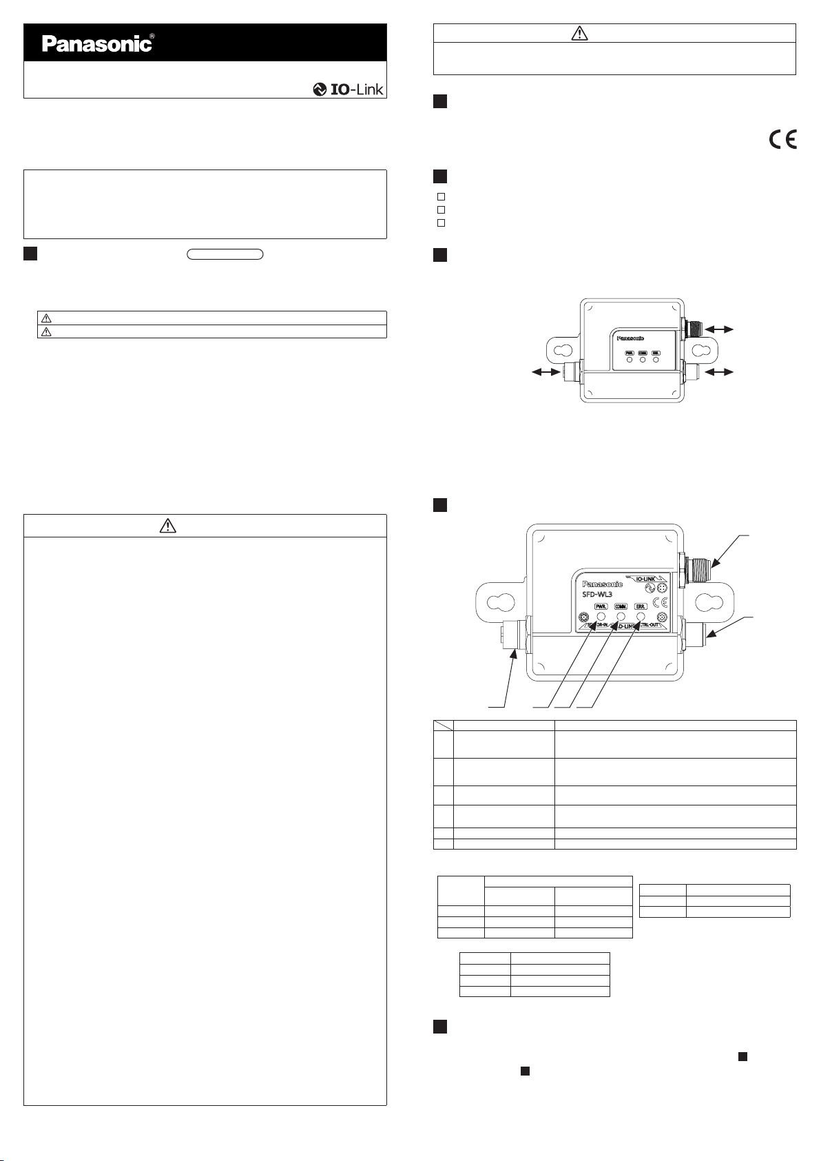
5DESCRIPTION OF PARTS
3
2
654
1
Name Function
1
8-core connector (socket) on
light curtain communication
side【SENSOR-IN】
Connection of 8-core connector cable (plug side) for connection of light cur-
tain. Connection of light curtain's receiver (or emitter)
2
8-core connector (plug) on
light curtain communication
side【CTRL-OUT】
Connection of 8-core connector cable (socket side) for connection of light
curtain. Connection of external device (PLC), power supply and light cur-
tain's emitter (or receiver).
3
Connector (plug) on IO-Link
communication side【IO-LINK】
Connection of IO-Link master unit (M12 connector).
4Power indicator【PWR.】Indication of the state of power supply to connectors on IO-Link communica-
tion side and light curtain side. (Notes:1)
5
Communication indicator【COMM.】
Indication of the state of IO-Link communication. (Notes:2)
6Error indicator【ERR.】Indication of error generation. (Notes:3)
Notes: 1) The Power indicator lights in the following patterns.
Connection state
IO-Link communica-
tion side
Light curtain side
Lights up Connection Connection
Flashes
Connection
Disconnected
OFF
Disconnected
(Irregular)
Notes: 2) The Communication indicator lights in the
following patterns.
IO-Link Communication states
Flashes
Communicating
OFF Not communicating
Notes: 3) The Error indicator lights in the following patterns.
Operating status
OFF
Normal operation
Lights up
IO-Link communication error
Flashes Internal malfunction
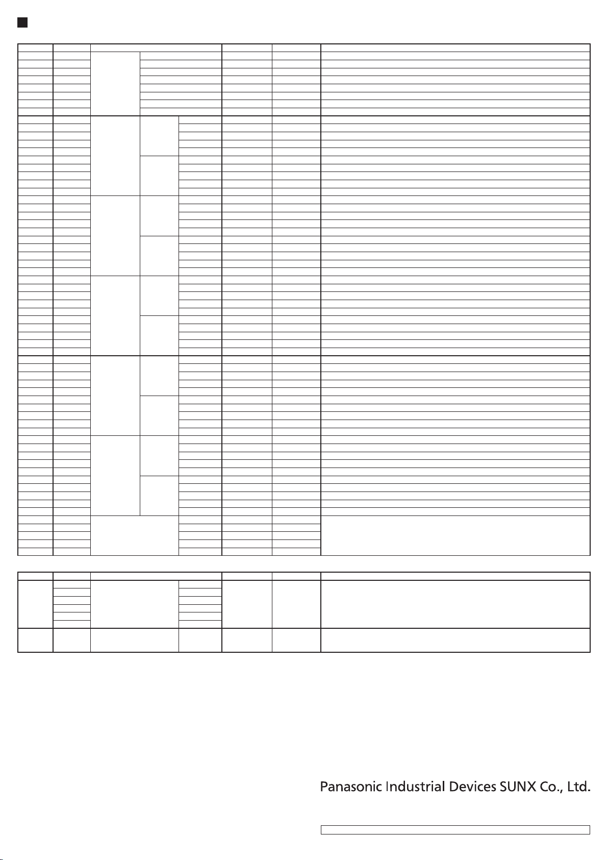
6FUNCTIONS
●The product connected to the IO-Link master unit enables monitoring the op-
eration status of the connected light curtain (Please refer to "14 PROCESS
DATA(PD)" and "15SERVICE DATA(SD)" for monitoring items).
●This product stores the old (before replacement) light curtain setting data inside
SFD-WL3, and copy setting data to the new (after replacement) light curtain after
replacement.
Note )
Writing is possible only for the same combination(model name,number and pitch of optical axis)of light curtain
that got setting saving information.

7INTERNAL CIRCUIT
● Circuit Congurations
Isolation (Note:1)
Main light curtain com-
munication circuit
Main IO-Link circuit
Power
supply
circuit
1
2
3
4
1
2
3
4
5
6
7
8
1
2
3
4
5
6
7
8
IO-Link
+V
N.C.
0V
C/Q
【CTRL_OUT】
+V
Synchronization
+
Synchronization
-
0V
+V
Synchronization
+
Synchronization
-
0V
Controller sideLight curtain side
【SENSOR_IN】
Internal circuit
Power
supply
circuit
Note: 1)The main light curtain communication circuit is isolated from the main IO-Link circuit inside the product.
8MOUNTING
● Observe the following tightening torque when installing the product: 5.5 N∙m max.
for M8 bolts or 2.5 N∙m max. for M6 bolts. Mount the product using two bolts as
shown in the diagram below.
●Mount the product in place before connecting connector cables.
●The product may be installed in any orientation or direction. Be sure to connect
the cables securely to prevent communication errors resulting from loosening or
detaching of cables or connectors due to its installation direction.
M8 bolt
Using M8 bolts for installation
(Use larger holes located toward the inside)
M6 bolt
Using M6 bolts for installation
(
Use smaller holes located toward the outside
)
9CONNECTION
●Turn OFF the power to the light curtain and IO-Link master unit before connecting
the product to the light curtain and IO-Link master unit.
●Various types of cable are available as optional parts for SF4D Series light cur-
tains. For details, visit our website (https://panasonic.net/id/pidsx/global).
Connection to light curtain
<When using the product by connecting it to the receiver side of light curtain>
1.
Connect the connector (plug side) on the 8-core bottom cap cable or 8-core ex-
tension cable connected to the light curtain's receiver to this product's 8-core con-
nector (socket side) located on the light curtain communication side.
8-core connector
(plug side)
8-core connector
(socket side)
Light curtain's
receiver
2.
Connect the connector (socket side)on the 8-core extension cable to this prod-
uct's 8-core connector (plug side)on the light curtain communication side.
8-core connector (plug side)
8-core connector
(socket side)
3.
Connect the 8-core extension cable connected in the above step 2 to the external
device (PLC), power supply and light curtain's emitter.
PLC, power
supply and
light curtain
<When using the product by connecting it to the emitter side of light curtain>
1.
Connect the connector (plug side)on the 8-core bottom cap cable or 8-core ex-
tension cable connected to the light curtain's emitter to this product's 8-core con-
nector (socket side)located on the light curtain communication side.
Light curtain's
emitter
8-core connector
(plug side)
8-core connector
(socket side)
2.
Connect the connector (socket side)on the 8-core extension cable to this prod-
uct's 8-core connector (plug side)on the light curtain communication side.
8-core connector
(plug side)
8-core connector
(socket side)
3.
Connect the 8-core extension cable connected in the above step 2 to the external
device (PLC), power supply and light curtain's receiver.
PLC, power
supply and
light curtain
<Terminal layout of connector on light curtain communication side>
Socket side
【SENSOR-IN】
Plug side
【CTRL-OUT】
Terminal arrangement for connection of receiver side
Terminal No. Functions
1 Control Output 2(OSSD2)
2 24V DC
3 Control Output 1(OSSD1)
4External device monitor input
5Synchronization +
6Synchronization -
7 0V
8
Output polarity setting / Lockout release input
Terminals arrangement for connection of emitter side
Terminal No. Functions
1Interlock setting input
2 24V DC
3Test / Reset input
4Auxiliary output
5Synchronization +
6Synchronization -
7 0V
8
Output polarity setting / Lockout release input
Connection to IO-Link master unit
Connect the M12 connector cable (optional)for communication with IO-Link master
unit to this product's connector on the IO-Link communication side.
<Terminal arrangement of M12 connector type>
Terminal No. Terminal Name Functions
1+V Power +V
2 N.C. -
3 0V Power 0V
4 C/Q
IO-Link communication
1
4
2
3
10
LIGHT CURTAIN SETTING DATA COPY FUNCTION
●This function reads the setting data stored in the light curtain and copies it in the
product's internal memory (nonvolatile memory).(You can not create and save
data le for external back up.)
●When the light curtain is replaced during maintenance or for other reasons, the
setting data stored in the product's internal memory can be written to the newly
installed light curtain. This facilitates the setting work and also prevents setting
errors.
Note )
This function cannot be used unless the product is connected with the IO-Link master unit and is able to use IO-
Link communication. For detailed information, see [
15
SERVICE DATA(SD)].
・
Recommended connection cable
"A Coding" cable manufactured
by TE Connectivity
(IEC-61076-101)

11
SPECIFICATIONS
Product name IO-Link Communication Unit for SF4D Series
Model No. SFD-WL3
Commu-
nication
method
Light curtain communi-
cation side RS-485 bidirectional communication (dedicated protocol)
IO-Link communication
side IO-Link specications: Ver. 1.1
Supply
voltage
Light curtain communi-
cation side 24V DC % Ripple P-P10% or less
IO-Link communication
side 24V DC % Ripple P-P10% or less
Power
consump-
tion
Light curtain communi-
cation side 15mA or less
IO-Link communication
side 30mA or less
Functions • IO-Link communication function
• Light curtain setting data copy function (Notes:1)
Number of light curtain units in series
connection
5 units (total number of light beams: 256 or less)
Protective structure IP64
Over voltage category Ⅰ
Pollution Degree 3
Operating altitude 2000m or less (Notes:2)
Ambient temperature -10 to +55˚C (No dew condensation or icing allowed), Storage: -25 to +60˚C
Ambient humidity 30 to 85% RH, Storage:30 to 95% RH
Con-
nection
method
Light curtain communi-
cation side 8-core cable (with M12 connector) for light curtain
IO-Link communication
side 4-core cable (with M12 connector) (Notes:3)
Weight (main unit only) Approx. 270g
Notes: 1) The product's internalmemory (nonvolatile memory)has a limited life. It cannot be used for more than
100,000 write operations.
2) Do not use or store the product in a high-pressure environment exceeding the atmospheric pressure at 0 m
altitude.
3)The product and IO-Link master unit must be connected with a cable of 0.3 mm2or more. The total length of
the cable must not exceed 20 m.
12
DIMENTIONS(Units: mm)
Through hole for M8 mounting bolt
[
Recommended tightening torque
:5.5(N・m)]
Through hole for M6 mounting bolt
[
Recommended tightening torque
:2.5(N・m)]
4-core M12 connector (plug)on IO-Link side
8-core M12 connector (plug)on light curtain side
8-core M12 connector (socket)on light curtain side
(
Through hole for M8 mounting bolt
)
(Through hole for M6 mounting bolt)
13
IO-LINK COMMUNICATION SPECIFICATIONS
IO-Link setting le (IODD)can be downloaded from our website (https://panasonic.
net/id/pidsx/global ).
Model No. SFD-WL3
Baud rate COM3(230.4kbps)
Minimum cycle time 1.5ms
Process data length 18byte
Vender ID 834
Device ID 0x050001
14
PROCESS DATA(PD)
Process data(Byte)
0 1 2 3 4 5 6 7 8 9 10 11 12 13 14 15 16 17
Reserved CH5 CH4 CH3 CH2 CH1
General
information
Description of individual channel data(CH1-CH5) Bit
Description
Detail
7654321076543210
Light received /
blocked
0:Light blocked
1:Light received
Stable light recep-
tion information
0:Unstable light reception
1:Stable light reception
Unstable light re-
ception information
0:No unstable light reception
1:Unstable light reception
Ambient light
information
0:No ambient light
1:Ambient light detected
―0
Emitter lockout
detection
0:Not exist
1:Exist
Receiver lockout
detection
0:Not exist
1:Exist
Light intensity
information
(Digital indicator)
00:[OFF]
10:[Level 2]
01:[Level 1]
11:[Level 3]
―0
General information Bit
Description
Detail
765432 1 0 7 6 5 4 3 2 1 0
OSSD output
monitor information
0:OFF
1:ON
―0
Light curtain com-
munication control
state(Note
)
0:Normal
1:Busy
Light curtain com-
munication control
result(Note
)
0:Normal
1:Abnormal
Emitter linkage
information
0:Not connected
1:Connected
Receiver linkage
information
0:Not connected
1:Connected
Number of units in
series connection
1 to 5(0001~0101)
※
0:
Not connect/6~15:Unused
―0
Note )
The light curtain communication control ag is for the light curtain setting information copy function.
+20
-30
+20
-25

15
SERVICE DATA(SD)
<Read Access>
Index
Sub index
Description
Format
Data length Remarks
16 0
IO-Link device
Vendor Name String 64byte
17 0 Vendor Text String 64byte
18 0 Product Name String 64byte
19 0 Product ID String 16byte
20 0 Product Text String 64byte
21 0 Serial Number String 8byte
22 0 H/W Version String 16byte
23 0 F/W Version String 16byte
65 0
CH1
Emitter
Model Name String 64byte
66 0 Serial Number String 8byte
67 0 Version String 16byte Version information of the light certain
68 0 Error Code UInteger 1byte Latest error code (Notes:1)(Refer to manual of SF4D)
71 0 Elapsed time UInteger 6byte
Elapsed time (year/month/day/hour/minute/second)after light curtain ON, 1 byte each
(Notes:2)
73 0
Receiver
Model Name String 64byte
74 0 Serial Number String 8byte
75 0 Version String 16byte Version information of the light certain
76 0 Error Code UInteger 1byte Latest error code (Notes:1)(Refer to manual of SF4D)
79 0 Elapsed time UInteger 6byte
Elapsed time (year/month/day/hour/minute/second)after light curtain ON, 1 byte each
(Notes:2)
81 0
CH2
Emitter
Model Name String 64byte
82 0 Serial Number String 8byte
83 0 Version String 16byte Version information of the light certain
84 0 Error Code UInteger 1byte Latest error code (Notes:1)(Refer to manual of SF4D)
87 0 Elapsed time UInteger 6byte
Elapsed time (year/month/day/hour/minute/second)after light curtain ON, 1 byte each
(Notes:2)
89 0
Receiver
Model Name String 64byte
90 0 Serial Number String 8byte
91 0 Version String 16byte Version information of the light certain
92 0 Error Code UInteger 1byte Latest error code (Notes:1)(Refer to manual of SF4D)
95 0 Elapsed time UInteger 6byte
Elapsed time (year/month/day/hour/minute/second)after light curtain ON, 1 byte each
(Notes:2)
97 0
CH3
Emitter
Model Name String 64byte
98 0 Serial Number String 8byte
99 0 Version String 16byte Version information of the light certain
100 0 Error Code UInteger 1byte Latest error code (Notes:1)(Refer to manual of SF4D)
103 0 Elapsed time UInteger 6byte
Elapsed time (year/month/day/hour/minute/second)after light curtain ON, 1 byte each
(Notes:2)
105 0
Receiver
Model Name String 64byte
106 0 Serial Number String 8byte
107 0 Version String 16byte Version information of the light certain
108 0 Error Code UInteger 1byte Latest error code (Notes:1)(Refer to manual of SF4D)
111 0Elapsed time UInteger 6byte
Elapsed time (year/month/day/hour/minute/second)after light curtain ON, 1 byte each
(Notes:2)
113 0
CH4
Emitter
Model Name String 64byte
114 0Serial Number String 8byte
115 0Version String 16byte Version information of the light certain
116 0Error Code UInteger 1byte Latest error code (Notes:1)(Refer to manual of SF4D)
119 0Elapsed time UInteger 6byte
Elapsed time (year/month/day/hour/minute/second)after light curtain ON, 1 byte each
(Notes:2)
121 0
Receiver
Model Name String 64byte
122 0 Serial Number String 8byte
123 0 Version String 16byte Version information of the light certain
124 0 Error Code UInteger 1byte Latest error code (Notes:1)(Refer to manual of SF4D)
127 0 Elapsed time UInteger 6byte
Elapsed time (year/month/day/hour/minute/second)after light curtain ON, 1 byte each
(Notes:2)
129 0
CH5
Emitter
Model Name String 64byte
130 0 Serial Number String 8byte
131 0 Version String 16byte Version information of the light certain
132 0 Error Code UInteger 1byte Latest error code (Notes:1)(Refer to manual of SF4D)
135 0 Elapsed time UInteger 6byte
Elapsed time (year/month/day/hour/minute/second)after light curtain ON, 1 byte each
(Notes:2)
137 0
Receiver
Model Name String 64byte
138 0 Serial Number String 8byte
139 0 Version String 16byte Version information of the light certain
140 0 Error Code UInteger 1byte Latest error code (Notes:1)(Refer to manual of SF4D)
143 0 Elapsed time UInteger 6byte
Elapsed time (year/month/day/hour/minute/second)after light curtain ON, 1 byte each
(Notes:2)
224 0
Light intensity information
CH1 UInteger 192byte Light intensity information each optical axis, 1 byte (8 bits)
b7: Light received / blocked (0: Light blocked, 1: Light received)
b6: Rear ambient light information (0: No ambient light, 1: Ambient light detected)
b5: Front ambient light information(0: No ambient light, 1: Ambient light detected)
b4 – b0: Light intensity information (32 levels)
225 0 CH2 UInteger 192byte
226 0 CH3 UInteger 192byte
227 0 CH4 UInteger 192byte
228 0 CH5 UInteger 192byte
<Write Access>
Index
Sub index
Description
Format Data length Remarks
240
1
Light curtain data access
(Notes:3)
CH1
String 1byte " R " :Light curtain setting data save (Notes:4)
" W " :Stored light curtain setting data write (Notes:5)
2 CH2
3 CH3
4 CH4
5 CH5
16 All CH
254 0 Light curtain restart All CH String 7byte " RESTART " (Notes:6)
Notes: 1) If the light curtain fails to maintain normal communication status, the error code will not be displayed.
2) The elapsed time is the time from energization start to power shutdown of the light curtain (not cumulative time). The default display immediately after the start is [1(Year)/1(month)/1(day)/0(hour)/0(minute)/0(second) ].
3) When light curtain information access is executed, OSSD outputs of the light curtain is xed to OFF. Also, while the light curtain information is being accessed, the bit of the light curtain communication control state becomes "1" and other controls
are not accepted. Do not turn off this product and the light curtain while accessing light curtain information. The setting information of the light curtain may be deleted.
4) Reads the data (blanking information and others)set in the light curtain and save it in the product's internal nonvolatile memory."R": Light curtain setting data save is possible only for all CH of "sub index _16".
5) Writes the light curtain setting data stored in the product to the connected light curtain. After Writting, please conrm that there is no abnormality in the communication control result (PD).
[Note that the stored setting data can be written only when the conguration (model code, number of light beams, light beam pitch)of the new light curtain is the same as that of the previous light curtain.]
6) After executing the light curtain information access, execute the light curtain restart and cancel the OFF xation of the OSSD outputs of the light curtain.
https://panasonic.net/id/pidsx/global
Overseas Sales Division (Head Ofce)
2431-1 Ushiyama-cho, Kasugai-shi, Aichi, 486-0901, Japan
Phone: +81-568-33-7861 FAX: +81-568-33-8591
For sales network, please visit our website.
PRINTED IN JAPAN © Panasonic Industrial Devices SUNX Co., Ltd. 2018
Other manuals for SF4D Series
2
This manual suits for next models
1
Other Panasonic Industrial Electrical manuals
Popular Industrial Electrical manuals by other brands

S&C
S&C TripSaver II Installation, Operation, and Configuration

Eaton
Eaton RMQ-Titan M22 Series Instruction leaflet

Siemens
Siemens 3VA9177-0VF40 operating instructions

Murata
Murata GQM2195C2E7R0BB12 Series Reference sheet

Murata
Murata GRM0225C1E9R2CA03 Series Reference sheet

Murata
Murata GJM1555C1H6R6WB01 Series Reference sheet

Murata
Murata GRM31MR71H394KA01 Series Reference sheet

Murata
Murata GRM1885C1H120GA01 Series Reference sheet

Stahl
Stahl 8188 Series operating instructions

Siemens
Siemens MICROMASTER 430 Maintenance Instruction

Lightstar
Lightstar LIGHTMAN 60/90 EB user manual

Allen-Bradley
Allen-Bradley ControlLogix Reference manual