1.2. Before Use
Be sure to disconnect the mains cord before adjusting the voltage selector.
Use a minus(-) screwdriver to set the voltage selector (on the rear panel) to the voltage setting for the area in which the unit will
be used. (If the power supply in your area is 110V or 120V, set to the “127V” position.)
Note that this unit will be seriously damaged if this setting is not made correctly. (There is no voltage selector for some countries,
the correct voltage is already set.)
1.3. Before Repair and Adjustment
Disconnect AC power, discharge unit AC Capacitors as such C5700, C5701, C5703, C5704, C5705, C5706 and C5707 through
a10Ω, 1W resistor to ground.
DO NOT SHORT-CIRCUIT DIRECTLY (with a screwdriver blade, for instance), as this may destroy solid state devices.
After repairs are completed, restore power gradually using a variac, to avoid overcurrent.
• Current consumption at AC 110-127V / 220-240V, at 50/60Hz in NO SIGNAL mode (at volume min in FM Tuner mode) should
be ~500 mA.
1.4. Protection Circuitry
The protection circuitry may have operated if either of the following conditions are noticed:
• No sound is heard when the power is turned on.
• Sound stops during a performance.
The function of this circuitry is to prevent circuitry damage if, for example, the positive and negative speaker connection wires are
"shorted", or if speaker systems with an impedance less than the indicated rated impedance of the amplifier are used.
If this occurs, follow the procedure outlines below:
1. Turn off the power.
2. Determine the cause of the problem and correct it.
3. Turn on the power once again after one minute.
Note:
When the protection circuitry functions, the unit will not operate unless the power is first turned off and then on again.
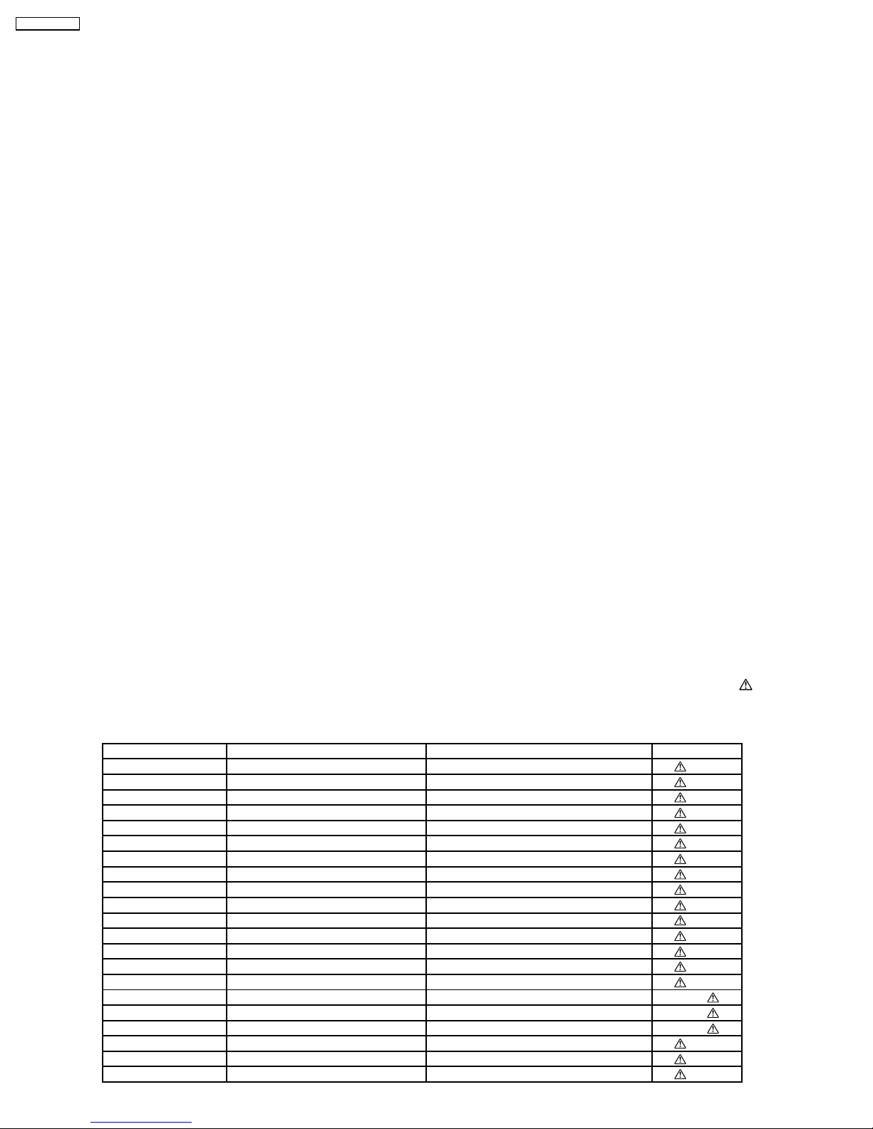
1.5. Safety Part Information
Safety Parts List:
There are special components used in this equipment which are important for safety.These parts are marked by in the
Schematic Diagrams & Replacement Parts List. It is essential that these critical parts should be replaced with manufacturer’s
specified parts to prevent shock, fire or other hazards. Do not modify the original design without permission of manufacturer.
Table 1
Reference No. Part No. Part Name & Description Remarks
18 RGRX0070J-A REAR PANEL [M]
A2 K2CQ2CA00007 AC CORD [M]
P5701 K2AA2B000017 AC INLET [M]
T5701 ETS48AB116AC MAIN TRANSFORMER [M]
T5751 ETS19AB256AG SUB TRANSFORMER [M]
F1 K5D802BNA005 FUSE [M]
L5702 ELF22V035B LINE FILTER [M]
S5701 K0ABCA000007 SW VOLTAGE SELECTOR [M]
DZ5701 ERZV10V511CS ZENER [M]
FP2901 K5G4013A0001 FUSE PROTECTOR [M]
36 RKMX0144-K TOP CABINET [M]
PC5701 B3PBA0000402 PHOTO COUPLER [M]
PC5702 B3PBA0000402 PHOTO COUPLER [M]
PC5720 B3PBA0000402 PHOTO COUPLER [M]
PC5799 B3PBA0000402 PHOTO COUPLER [M]
PCB2 REPX0622G SMPS P.C.B. [M] (RTL)
PCB8 REPX0622G AC INLET P.C.B. [M] (RTL)
PCB13 REPX0622G VOLTAGE SELECTOR P.C.B. [M] (RTL)
51 RMZ0339 ZENER COVER [M]
68 REXX0686 WHITE WIRE (VOLTAGE SELECTOR) [M]
69 REXX0687 BLUE WIRE (VOLTAGE SELECTOR) [M]
4
SA-AK970GCP