Panasonic INDUSTRY PAN9028 Quick setup guide

Wireless Connectivity
PAN9028
Wi-Fi Dual Band 2.4 G z/5 G z and
Bluetooth
®
Module
Module Integration Guide
Rev. 1.0
PAN9028 Wi-Fi/Bluetooth Module 1 About This Document
Module Integration Guide Rev. 1.0 Page 2 of 45
Overview
The PAN9028 is a 2.4 G z/5 G z ISM band Wi-Fi
and Bluetooth radio module, which includes a
wireless radio and a power management IC for
easy integration of Wi-Fi and Bluetooth connectivity
into various electronic devices.
Features
•
Dual band 2.4 G z/5 G z 802.11 a/b/g/n/ac Wi-Fi
and Bluetooth combo module
•
Supports 802.11i security standards through AES,
CCMP, and more security mechanism
•
802.11e Quality of Service is supported for
multimedia application
•
IEEE 802.11ac (Wave 2), 1×1 spatial stream with
data rates up to 433 Mbps (MCS9, 80 M z
channel bandwidth)
•
IEEE 802.11ac MU-MIMO beamformee
•
Bluetooth 5 (includes Low Energy)
•
Dual simultaneous and independent WLAN and
Bluetooth operation
•
Dynamic Rapid Channel Switching (DRCS) for
simultaneous operation in 2.4 G z and 5 G z
bands
•
Indoor location and navigation with
IEEE 802.11mc
•
Coexistence interface for arbitration of co-located
WLAN, Bluetooth, or mobile wireless system
(e.g. LTE or ZigBee
®
)
•
Generic interfaces include SDIO 3.0 and high
speed UART for host processor connection
•
Software driver Linux
®
Characteristics
•
Surface Mount Type (SMT)
24 mm × 12 mm × 2.8 mm
•
NXP
®
88W8987 WLAN 2.4 G z/5 G z and
Bluetooth single-chip solution inside
•
Single power supply: 3.3 V with Marvell
®
88PG823 Power Management IC (optional)
•
Tx power: 16 dBm at 802.11b
•
Rx sensitivity: -97 dBm at 802.11b DSSS 1 Mbps
•
IEEE 802.11ac 20 M z, 40 M z, 80 M z
channel bandwidth
•
Long and Short Guard Interval support
•
Current consumption Wi-Fi typical 320 mA (at Tx)
and 70 mA (at Rx)
•
SDIO 1 bit or 4 bit
•
Wide temperature range of -30 °C to 85 °C
Block Diagram
Chip
Antenna
SPDT
88W8987
Radio SoC
UART
GPIOs
PDN
V
DD
+3.3 V
BPF
RF Pad
PAN9028
Wi-Fi a d Bluetooth
â
Radio Module
IEEE 802.11 a/b/g/ /ac
Bluetooth 5 (BR, Low E ergy, a d EDR)
DPX
SPDT
PCM Interface
SDIO Interface
Sleep Clock
RF SW
PMIC
88PG823
Crystal
26 M z
V
IO
/V
IOSD
COEX

PAN9028 Wi-Fi/Bluetooth Module 1 About This Document
Module Integration Guide Rev. 1.0 Page 3 of 45
By purchase of any of the products described in this document the customer accepts the document's
validity and declares their agreement and understanding of its contents and recommendations. Panasonic
Industrial Devices Europe Gmb (Panasonic) reserves the right to make changes as required at any time
without notification. Please consult the most recently issued
Module Integration Guide before initiating or
completing a design.
© Panasonic Industrial Devices Europe Gmb 2021.
This specification sheet is copyrighted.
Reproduction of this document is permissible only if reproduction is
without alteration and is accompanied by all associated warranties, conditions, limitations, and notices.
Do
not disclose it to a third party.
All rights reserved.
This Module Integration Guide does not lodge the claim to be complete and free of mistakes.
E gi eeri g Samples (ES)
If Engineering Samples are delivered to the customer, these samples have the status “Engineering
Samples”. This means that the design of this product is not yet concluded. Engineering Samples may be
partially or fully functional, and they may differ from the published Product Specification.
Engineering Samples are not qualified and they are not to be used for reliability testing or series
production.
Disclaimer
The customer acknowledges that samples may deviate from the Module Integration Guide and may bear
defects due to their status of development and the lack of qualification mentioned above.
Panasonic rejects any liability or product warranty for Engineering Samples. In particular, Panasonic
disclaims liability for damages caused by:
The use of the Engineering Sample other than for evaluation purposes, particularly the
installation
or integration in another product to be sold by the customer,
Deviation or lapse in function of the Engineering Sample,
Improper use of the Engineering Sample.
Panasonic Industrial Devices Europe Gmb disclaims any liability for consequential and incidental
damages. In case of any queries regarding the Engineering Samples, please contact your local sales
partner or the related product manager.
The information contained herein is presented only as guidance for Product use. No responsibility is
assumed by Panasonic for any infringement of patents or any other intellectual property rights of third
parties that may result from the use of Product. No license to any intellectual property right is granted by
this document, whether express or implied, by estoppel or otherwise.
Description of hardware, software, and other information in this document is only intended to illustrate the
functionality of the referred Panasonic product. It should not be construed as guaranteeing specific
functionality of the product as described or suitable for a particular application.
Any provided (source) code shall not be used or incorporated into any products or systems whose
manufacture, use or sale is prohibited under any applicable laws or regulations.
Any outlined or referenced (source) code within this document is provided on an “as is” basis without any
right to technical support or updates and without warranty of any kind on a free of charge basis according
to § 516 German Civil Law (BGB) including without limitation, any warranties or conditions of title, non
infringement, merchantability, or fitness for a particular purpose. Customer acknowledges that (source)
code may bear defects and errors.

PAN9028 Wi-Fi/Bluetooth Module 1 About This Document
Module Integration Guide Rev. 1.0 Page 4 of 45
The third-party tools mentioned in this document are offered by independent third-party providers who are
solely responsible for these products. Panasonic has no responsibility whatsoever for the performance,
product descriptions, specifications, referenced content, or any and all claims or representations of these
third-party providers. Panasonic makes no warranty whatsoever, neither express nor implied, with respect
to the goods, the referenced contents, or any and all claims or representations of the third-party providers.
To the maximum extent allowable by Law Panasonic assumes no liability whatsoever including without
limitation, indirect, consequential, special, or incidental damages or loss, including without limitation loss of
profits, loss of opportunities, business interruption, and loss of data.

PAN9028 Wi-Fi/Bluetooth Module 1 About This Document
Module Integration Guide Rev. 1.0 Page 5 of 45
Table of Co te ts
1
About This Docume t ......................................................................................................................... 7
1.1
Purpose and Audience .................................................................................................. 7
1.2
Revision istory ............................................................................................................. 7
1.3
Use of Symbols ............................................................................................................. 7
1.4
Related Documents ....................................................................................................... 8
2
Overview .............................................................................................................................................. 9
3
PAN9028 Module ............................................................................................................................... 10
3.1
Block Diagram ............................................................................................................. 10
3.2
Land Pattern ................................................................................................................ 11
3.3
Footprint ...................................................................................................................... 12
3.4
Solder Mask ................................................................................................................. 13
3.5
Placement .................................................................................................................... 13
4
Power Supply .................................................................................................................................... 15
5
RF Path .............................................................................................................................................. 16
5.1
External Antenna ......................................................................................................... 16
5.2
RF Trace ...................................................................................................................... 16
6
O e-Layer Example for Module Varia t ENWF940[x]A1EF ........................................................... 19
7
mSDIO Adapter ................................................................................................................................. 20
7.1
Functional Blocks ........................................................................................................ 20
7.2
Resistor Jumper Configuration .................................................................................... 20
7.3
Part Placement ............................................................................................................ 21
8
Refere ce Desig .............................................................................................................................. 22
8.1
Schematic .................................................................................................................... 22
8.2
PCB Layout ................................................................................................................. 22
9
Cautio s ............................................................................................................................................ 24
9.1
Design Notes ............................................................................................................... 24
9.2
Installation Notes ......................................................................................................... 24
9.3
Usage Condition Notes ................................................................................................ 25
9.4
Storage Notes .............................................................................................................. 25
9.5
Safety Cautions ........................................................................................................... 25
9.6
Other Cautions ............................................................................................................ 26
9.7
Restricted Use ............................................................................................................. 27
10
Regulatory a d Certificatio I formatio ....................................................................................... 28
10.1
Federal Communications Commission (FCC) for US .................................................. 28
10.2
Innovation, Science, and Economic Development (ISED) for Canada ........................ 32
10.3
European Conformity According to RED (2014/53/EU) ............................................... 40
10.4
Bluetooth Qualification ................................................................................................. 44
10.5
Ro S And REAC Declaration ................................................................................... 44
11
Co tact Details .................................................................................................................................. 45
11.1
Contact Us ................................................................................................................... 45

PAN9028 Wi-Fi/Bluetooth Module 1 About This Document
Module Integration Guide Rev. 1.0 Page 6 of 45
11.2
Product Information ..................................................................................................... 45

PAN9028 Wi-Fi/Bluetooth Module 1 About This Document
Module Integration Guide Rev. 1.0 Page 7 of 45
1 About This Docume t
1.1 Purpose a d Audie ce
This Module Integration Guide is intended to support the easy integration of the PAN9028 into a
product and to ensure the compliance with regulatory requirements.
This guide gives an overview about the hardware design requirements by providing a reference
design, which is the evaluation board of the PAN9028.
It is intended for hardware design and Original Equipment Manufacturers (OEM) engineers.
The product is referred to as “the PAN9028” or “the module” within this document.
1.2 Revisio History
Revisio Date Modificatio s/Remarks
0.1 2018-05-08 First preliminary version
0.2 2021-03-15 Changed SDIO stick to mSD stick. New design. Updated formatting.
Changed document type and structure (“Design Guide” into “Module
Integration Guide”). Corrected current consumption. Corrected cutout
area. Updated chapter “Power Supply”. Removed chapter “Power
Configuration Examples for ENWF940[x]A1EF”. Updated chapter
“Placement”. Updated picture “Solder Mask Layout”. Updated chapter
“Functional Blocks”.
1.0 2021-08-26 Updated pictures: “Block Diagram” and “Land Pattern”. Updated features.
Added regulatory chapter. Changed mSD Reference Design to mSD-U
1.3 Use of Symbols
Symbol Descriptio
Note
Indicates important information for the proper use of the product.
Non-observance can lead to errors.
Atte tio
Indicates important notes that, if not observed, can put the product’s functionality
at risk.
Tip
Indicates useful information designed to facilitate working with the module and
software.

PAN9028 Wi-Fi/Bluetooth Module 1 About This Document
Module Integration Guide Rev. 1.0 Page 8 of 45
Symbol Descriptio
[chapter number]
[chapter title]
Cross Refere ce
Indicates cross references within the document.
Example:
Description of the symbols used in this document 1.3 Use of Symbols.
Requireme t
Indicates a requirement that must be met before the corresponding tasks can be
completed.
Result
Indicates the result of a task or the result of a series of tasks.
This fo t GUI Text
Indicates fixed terms and text of the graphical user interface.
Example:
Click Save.
Me u > Me u item Path
Indicates a path, e.g. to access a dialog.
Example:
In the menu, select File > Setup page.
This font File Names, Messages, User I put
Indicates file names or messages and information displayed on the screen or to
be selected or entered by the user.
Examples:
pan1760.c contains the actual module initialization.
The message Failed to save your data is displayed.
Enter the value Product 123.
Key Key
Indicates a key on the keyboard, e.g. F10 .
1.4 Related Docume ts
For related documents please refer to the Panasonic website 11.2 Product Information.

PAN9028 Wi-Fi/Bluetooth Module 2 Overview
Module Integration Guide Rev. 1.0 Page 9 of 45
2 Overview
The PAN9028 is a dual band 2.4 G z and 5 G z 802.11 a/b/g/n/ac Wi-Fi radio module with
integrated Bluetooth BR/EDR/Low Energy (LE), specifically designed for highly integrated and
cost-effective applications. The simultaneous and independent operation of the two standards
enables very high data rates (802.11ac) and low-power operation (Bluetooth LE). Integrated
power management, a fast dual-core CPU, 802.11i security standard support, and high-speed
data interfaces deliver the performance for the speed, reliability, and quality requirements of
next generation products. Tx power calibration data, Wi-Fi, and Bluetooth system parameters
are pre-stored on the One Time Programmable memory of the PAN9028 during production at
Panasonic. This simplifies passing the certification process for PAN9028 customers.
Furthermore, the module reduces design, test, and calibration effort resulting in reduced time-
to-market compared to discrete solutions.
Integrating Wi-Fi and Bluetooth wireless connectivity allows high throughput applications for
industrial devices and appliances. The combination of Wi-Fi and Bluetooth provides the highest
flexibility for connectivity.
This Module Integration Guide applies to the PAN9028 WLAN/Bluetooth combo module and the
PAN9028 mSDIO Adapter development platform.
This document is structured into two main parts:
•
The hardware integration of the PAN9028 module.
•
The PAN9028 mSDIO Adapter as an example for the module integration.
For related documents please refer to 11.2 Product Information.
PAN9028 Wi-Fi/Bluetooth Module 3 PAN9028 Module
Module Integration Guide Rev. 1.0 Page 10 of 45
3 PAN9028 Module
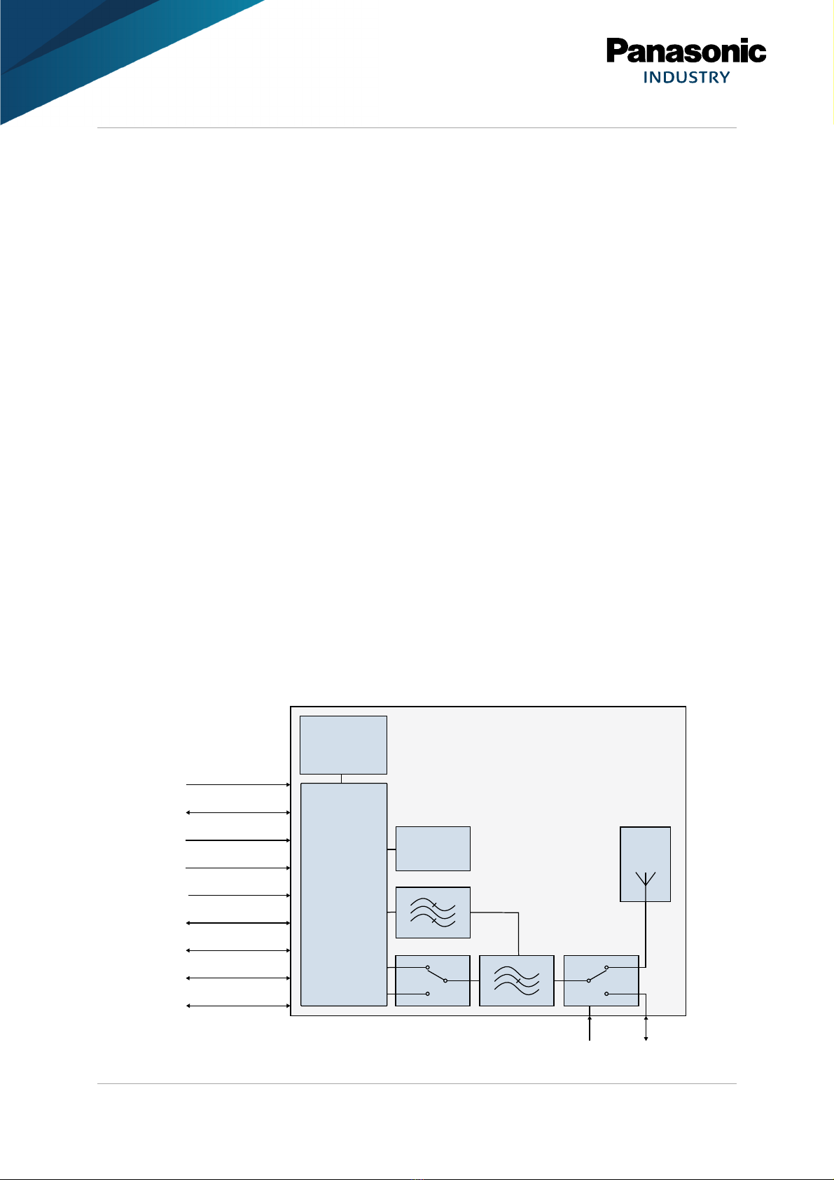
3.1 Block Diagram
For Module Varia t ENWF940[x]A1EF:
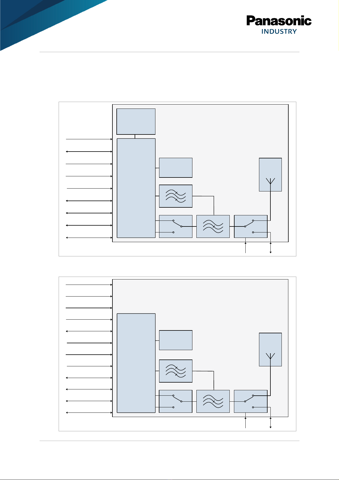
For Module Varia t ENWF940[x]A2EF:
Chip
Antenna
SPDT
88W8987
Radio SoC
UART
GPIOs
PDN
VDD +3.3 V
BPF
RF Pad
PAN9028
Wi-Fi a d Bluetoothâ Radio Module
IEEE 802.11 a/b/g/ /ac
Bluetooth 5 (BR, Low E ergy, a d EDR)
DPX
SPDT
PCM Interface
SDIO Interface
Sleep Clock
RF SW
PMIC
88PG823
Crystal
26 M z
VIO/VIOSD
COEX
Chip
Antenna
SPDT
88W8987
Radio SoC
UART
GPIOs
PDN
V
DD
+1.1 V
BPF
RF Pad
PAN9028
Wi-Fi a d Bluetooth
â
Radio Module
IEEE 802.11 a/b/g/ /ac
Bluetooth 5 (BR, Low E ergy, a d EDR)
DPXSPDT
PCM Interface
SDIO Interface
Sleep Clock
RF SW
Crystal
26 M z
V
IO
/V
IOSD
COEX
V
DD
+1.8 V
V
DD
+2.2 V
V
DD
+3.3 V
Other manuals for INDUSTRY PAN9028
2
Table of contents
Other Panasonic Wireless Module manuals

Panasonic
Panasonic PAN9026 User manual

Panasonic
Panasonic DNSK-P11 User manual

Panasonic
Panasonic ET-WML100 User manual

Panasonic
Panasonic DNSK-P11 Manual

Panasonic
Panasonic PAN1026A Guide

Panasonic
Panasonic AJ-WM50P User manual

Panasonic
Panasonic PAN1026A Guide

Panasonic
Panasonic PAN1780 Quick setup guide

Panasonic
Panasonic PAN1740 Guide
Popular Wireless Module manuals by other brands


Cooper Wiring Devices
Cooper Wiring Devices ESPIRE RF RFAPM installation instructions

Yuga
Yuga CLM920 user manual

Waldmann
Waldmann TALK Bluetooth operating manual

Telit Wireless Solutions
Telit Wireless Solutions UC864-G Hardware user's guide

Ebyte
Ebyte E07-900M10S manual

Quectel
Quectel SC690A Series Hardware design


