Pando P-496 Operating manual

EN
- 1 -
User, Installation
Manual
and Guarantee Certificate
Certificación de Producto U.L.
(U.S.A. - Canadá) U.L. 507-2001
Pando
Pando
by

EN
- 2 -
** The symbol on the product or its packaging indicates that this product cannot
be treated as ordinary household waste. The product must be taken to an
electrical and electronic device collection point for recycling. By ensuring that
this product is disposed of properly you will be helping to avoid the possible
consequences for the environment and public health which might result from
improper handling of this product. To obtain more detailed information about
recycling this product, please contact your local authority, household waste
service or the shop where you purchased the product. This electrical appliance
is marked in accordance with European directive 2002/96/EC on waste electrical
and electronic equipment (WEEE).
First of all, we would like to congratulate you on your choice of a Pando Extractor Hood, as well as thanking
you for placing your trust in our firm.
This manual is a guide to the correct installation, use and maintenance to care for your new Extractor Hood.
The manufacturer is not liable for any inaccuracies due to printing or transcription errors
which may be contained in this manual. It reserves the right to make any modifications it
deems necessary or useful to its own products without affecting their essential functional
and safety features.
* Set-up manual enclosed in a separate document, in the bag with
documentation.
This manual covers different models from this manufacturer. To determine which parts
and functions match your hood model, REFER TO THE SPECIFIC INSTALLATION
MANUAL FOR YOUR MODEL.
INTRODUCTION
CONTENTS
1. Safety Instructions ...............................Page 3
2. Installation instructions and recommendations .......Page 5
3. Technical specifications of motors ..................Page 12
4. Instructions for use and handling of controls .........Page 13
5. Cleaning and maintenance ........................Page 21
6. Details to take into account with special models ......Page 27
7. Trouble-shooting. ................................Page 29
8. Technical after-sales service, guarantee certificate
and registration ....................................Page 32
COLLECTION OF
APPLIANCES

EN
- 3 -
This applicance can be used by children aged 8 or over and people with reduced physical, sensory or
mental abilities or lack of experience and knowledge only if they are given appropriate supervision or training
regarding the safe use of the appliance and understand the risks involved. Children must not play with the
appliance. Cleaning and user maintenance must not be performed by children without supervision.
• Remove the packaging immediately when you receive the appliance. Check its general appearance and
in the event that you see any problem inform your dealer or installer immediately.
• Your appliance is intended for normal domestic use. It is not to be used for commercial or industrial
purposes or for any purpose other than those for which it was designed.
• The supplier makes no guarantee as to any consequences and harm arising from incorrect installation or
misuse of the appliance.
• Never attempt to modify the features of this appliance as this represents a risk. Repairs must be carried
out exclusively by an authorised specialist technical service. To avoid risks, all tampering with the appliance
is prohibited, including replacing the power cable.
• WARNING: To reduce The Risk Of Fire Or Electric Shock, Do Not Use This Fan With Any Solid-State
Speed Control Device.”
• If the hood is not fitted with a power cable and a plug, or some other means of disconnecting it from the
mains power supply featuring a contact gap in all poles to assure total disconnection under the conditions
provided for by overvoltage class III, it must be equipped with means of disconnection from the fixed
installation in accordance with installation regulations (omnipolar circuit breakers connected directly to the
power terminals, which must have a contact gap in the poles to cut off the electrical power supply in the
event of class III overvoltage).
• It must be possible to disconnect the device from the power supply after installation. This can be done by
making the plug accessible or by fitting a circuit breaker in the electrical installation in accordance with the
rules for the installation.
• If the power cable is damaged, it must be replaced by the manufacturer, its after-sales service or similar
qualified staff in order to avoid any danger.
• Special care must be taken when drilling into walls or ceilings to ensure there are no concealed electrical
cables, pipes, metal girders, etc. as drilling into them can cause serious damage, divert electrical current
or transmit noise and vibration.
• IMPORTANT: For installation, always switch off the power supply at the appropriate differential or
circuit breaker in the main house fuse box before making the electrical connection for the appliance.
• WARNING: Always disconnect the hood from the power supply by unplugging it or using the
appropriate differential or circuit breaker in the main house fuse box before beginning cleaning or
maintenance work. Never use steam or high-pressure devices to clean your hood (electrical safety
regulations). See section 5, page 24-29, cleaning and maintenance.
• Never cook foodstuffs directly over the flame or have the gas burners on under the hood without cooking
recipients over them (flames sucked in might damage the appliance and the warranty would be voided). The
appliance is not authorised for use over a solid fuel burner (wood, coal, etc.).
Frying under the hood must be constantly supervised because oils and fats can catch fire at very high
temperatures. Do not flambé food under the hood.
• Caution: risk of burns. Accessible parts of the appliance can heat up when used with cooking equipment.
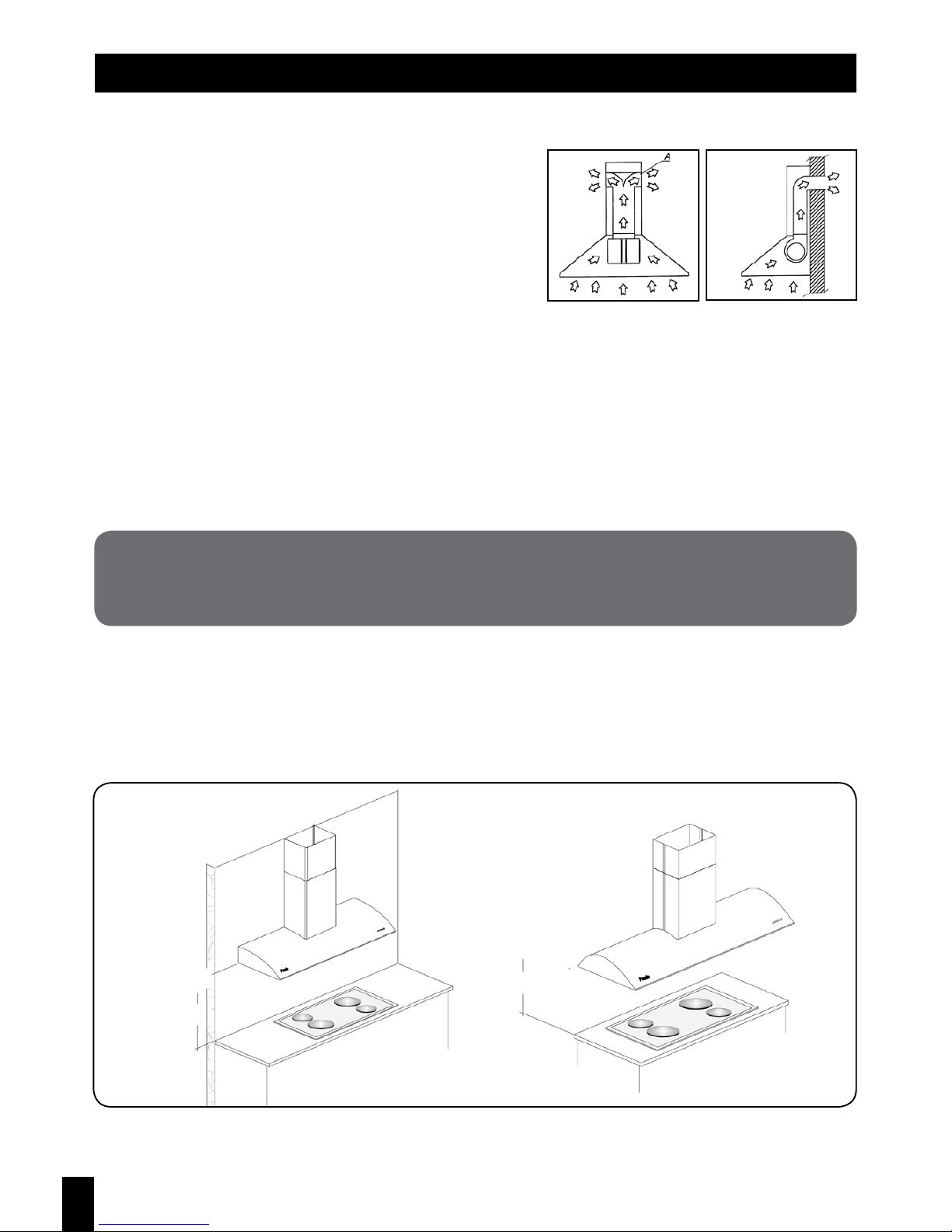
• The distance between the surface on which the cooking containers stand on the hob and the bottom of
the hood must be at least 65cm if the extractor hood is fitted over a gas cooker. If the gas cooker installation
instructions specify a greater distance, this must be taken into account.
1. SAFETY INSTRUCTIONS - Read and save these instructions

EN
- 4 -
• “WARNING: TO REDUCE THE RISK OF FIRE, USE ONLY METAL DUCTWORK.”
• Clean and replace filters at the proper intervals. Build-ups of grease can cause fires. Never use the hood
without the grease filter.
• Installation must comply with regulations in force concerning the ventilation of closed rooms. Specifically,
the air extracted must not exit through a pipe used to remove fumes from devices which run on gas or some
other fuel (central heating installations, etc.).
• Proper ventilation must be provided where the hood is used at the same time as other appliances run from
a power source other than electricity so that the hood does not suck in compound gases.
- Attention! When a hood with a suction system is in use at the same time as a heat source depending
on air in the atmosphere (gas, oil, coal heaters, open fire, etc.) great care should be taken to ensure that
the hood does not suck in some of the air to be used for combustion as dangerous amounts of carbon
monoxide could build up in the premises or home, placing lives at risk. Where an extractor hood is installed
in connection or together with a combustion element such as a stove, fireplace or local heating system, the
manufacturer of these elements must be consulted to ensure efficient, risk-free operation
• The maximum permitted depression is 0.04 mbar. These conditions allow the hood to work properly. To
ensure these conditions there must be a constant entrance of air in order to avoid the air being trapped (it
is advisable to have a ventilation grille for this purpose). Neither windows nor doors can serve this purpose.
• The electrical mains power supply must be steady and meet the stated electrical requirements (see the
device features panel). If it is not constant and there are fluctuations in voltage, intensity or frequency,
harmonics, voltage gaps, surges, electrical storms, etc. the hood may not work properly and can even be
damaged, and in this case the repair would not be covered by the warranty. If these situations occur the
hood should be disconnected and an electrician or electricity company contacted to solve the problem with
the power supply.
• The hood is an electrical appliance to be used for extracting fumes, and it may not be used to support
objects or utensils.
• In our ongoing efforts to improve our products, we reserve the right to make any modifications to the
technical, operating or aesthetic features which form part of their development.
1. SAFETY INSTRUCTIONS (continuation) - Read and save these instructions
IMPORTANT SAFETY INSTRUCTIONS - Read and save these instructions
WARNING:
TO REDUCE THE RISK OF FIRE, ELECTRICAL SHOCK, OR INJURY TO PERSONS,
OBSERVE THE FOLLOWING:
a) Use this unit only in the manner intended by the manufacturer. If you have questions, contact the
manufacturer.
b) Before servicing or cleaning unit, switch power off at service panel and lock service panel to prevent
power from being switched on accidentally. When the panel cannot be locked, attach a tag to the
service panel to indicate power has been switched off for maintenance.

EN
- 5 -
(The whole installation process should only be carried out by qualified professionals, professional
installers or official technical service staff).
Before beginning installation, check that all the components are in order. If they are not, contact the vendor
and do not proceed with the installation. Damage to the unit once installed, such as scratches, dents, etc. are
not covered by the guarantee
2. INSTALLATION INSTRUCTIONS AND RECOMMENDATIONS
Read and save these instructions
VERY IMPORTANT
THE PROTECTIVE PLASTIC MUST NOT BE REMOVED FROM THE HOOD UNTIL ITS
INSTALLATION IS COMPLETE.
WARNING – TO REDUCE THE RISK OF A RANGE TOP GREASE FIRE:
a) Keep fan, filters and grease laden surfaces clean.
b) Always turn hood ON when cooking at high heat.
c) Use high range setting on ranges only when necessary. Heat only on low to medium setting.
d) Don’t leave range unattended when cooking.
e) Always use cookware and utensils appropriate for the size surface element and for the type and amount
of food being prepared.
WARNING – TO REDUCE THE RISK OF INJURY TO PERSONS IN THE EVENT OF A RANGE TOP
GREASE FIRE. OBSERVE THE FOLLOWING:
a) Smother flames with a close fitting lid, cookie sheet or metal tray, then turn off the burner. Be careful to
prevent burns. If the flames do not go out immediately, EVACUATE AND CALL THE FIRE DEPARTMENT.
b) NEVER PICK-UP A FLAMING PAN- You may be burned.
c) DO NOT USE WATER, including wet dishcloths or towels – a violent steam explosion will result.
d) Use an extinguisher ONLY if:
1) You have a CLASS ABC extinguisher and you know how to operate it
2) The fire is small and contained in the area where it started
3) The fire department is being called
4) You can fight the fire with your back to an exit
WARNING- TO REDUCE THE RISK OF FIRE, ELECTRIC SHOCK, OR INJURY TO PERSONS, OBSERVE
THE FOLLOWING:
a) Installation work and Electrical Wiring MUST be done by Qualified Person (s) in Accordance with all
Applicable Codes and Standards, including Fire-Rated Construction.
b) Sufficient air is needed for proper combustion and exhausting of gases through the flue (chimney) of
fuel burning equipment to prevent back drafting. Follow the heating equipment manufacturer’s guideline
and safety standards such as those published by the National Fire Protection Association (NFPA) and the
American Society of Heating, Refrigeration and Air Conditioning Engineers (ASHRAE) ant he local code
authorities.
c) When cutting or drilling into wall or ceiling, do not damage electrical wiring and other hidden utilities.
d) Ducted fans must always be vented to the outdoors.
CAUTION: FOR GENERAL VENTILATING USE ONLY. DO NOT USE TO EXHAUST
HAZARSOUS OR EXPLOSIVE MATERIALS AND VAPORS. FOR RESIDENTIAL
APPLICATION ONLY.

EN
- 6 -
Pay special attention to all the instructions given below.
• Use an air extraction flue which is as short as possible.
• Limit the number of bends in the flue, and ensure that any which are used are as open as possible.
• Use a material approved by regulations.
• Avoid drastic differences in section (constant diameter recommended; consult examples).
2.1. ASPIRATION VERSION
(Fig. 1).
Hood in filter
version
(Fig. 2).
Hood in suction
version
VERY IMPORTANT:
INOXPAN S.L. TAKES NO RESPONSIBILITY FOR THE OPERATION OF ITS APPLIANCES IF
THEY ARE NOT CONNECTED TO A FLUE OF THE DIAMETER RECOMMENDED FOR EACH
MOTOR VERSION.
• TYPE OF FLUE: performance will depend on the material of which the flue is made. The type of material
can affect noise level and the friction of the flow.
For silenced installation we recommended using our special SEC System piping for the flue. Consult our
distributor.
In the event that it is not possible to discharge cooking
fumes and steam outside, the filter version of the hood
may be used (Fig. 1) (depending on the version, consult
distributor) by fitting an active carbon filter kit. The fumes
and steam are recycled and emitted through the grille at the
top (A). You are informed that if this option is used aspiration
will be diminished and the noise level is higher than with the
aspiration version.
The hood features a top air outlet to discharge fumes to
the outside in the aspiration version (Fig. 2). Wherever
possible, this is the best option.
Note: The distance must be at least 650mm; also abide by the distance specified by the cooker
manufacturer if this is greater. The ideal distance between the hob and the bottom of the hood is
650mm; if it is greater there is a risk of fumes escaping at the sides of the hood.
Ideal height 650mm
(Depending on model)
Wall-mounted hood Island hood
Ideal height
650mm
• DETERMINING HEIGHT: the ideal distance from the base of the hob up to the bottom of the hood body is
65cm. If this distance is increased, there is a risk of fumes escaping (diagram on page 5)
• “WARNING: TO REDUCE THE RISK OF FIRE, USE ONLY METAL DUCTWORK.”

EN
- 7 -
If the above instructions are not followed, the supplier will not be bound by the warranty in the event
of problems with flow or noise level.
Flaps to open under pressure
(not included)
non-return valves
(not included)
RIGHT
WRONG
NOTE: Centre the hood over the cooking area
• HOOD WIDTH: the width of the hood must always be greater than that of the cooking area. If it is narrower
there is a risk of fumes escaping at the sides (diagram on page 5). (Depending on model)
• CENTRING THE HOOD: the hood must be centred so that the filters in it are aligned with the cooking area.
• VENTILATION AND AIR CURRENTS: all hood installations must have an air inlet, preferably located
in front of the hood, and not have a second inlet which would create currents of air. If there is no air inlet
problems will arise with depression and excess pressure in the atmosphere and the hood motor will perform
poorly.
• OUTSIDE FLUE OUTLET: The outlet of the flue must be covered with flaps which open under pressure
(diagram on page 5). Under no circumstances should gas grilles or any others which obstruct the free
passage of air be used. Nor should air outlets be left uncovered as foreign elements might get in (water,
strong winds, nests, etc.) and obstruct the outlet flow, possibly damaging components in the hood.
• REDUCTIONS IN FLUE DIAMETER: The following should be borne in mind where the route taken by
the flue means the diameter of the pipe has to be reduced. First of all, it must be clearly understood that
reducing the flue diameter ALWAYS DIMINISHES ASPIRATION. Therefore, when it is NECESSARY to do
so, the premises shown in the diagrams on page 7 must be taken into account..
• NON-RETURN VALVE: it is advisable to fit these in shared installations, where several flues converge into a
single one, to prevent accumulations of fumes and the entry of fumes and smells from other hoods.

EN
- 8 -
* IMPORTANT: Whenever there are more than two bends or reductions in the flue, the distance
between them must be at least 1 metre in order to give time for the speed and pressure of the air
flow to recover. For example, if two 90º bends are fitted 20cm apart, this will cause a blocking effect,
drastically reducing aspiration power and increasing noise level.
* IMPORTANT: Always avoid flues running downwards, as this drastically reduces extraction capacity.
Drawing D
WORSE BETTER
4. Keep the curves or bends in the
installation to a minimum. If they
do exist, try to keep the angle as
open as possible.
Drawing C
WRONG RIGHT
3. Never fit reductions next to
curves or bends in the installation.
They must always be in straight
sections and as far as possible
from the hood.
Reduction in flue
Drawing B
2. Always reduce the diameter of
the flue in steps.
Reduction from
Ø 150mm to Ø 135 mm
Reduction from
Ø 135mm to Ø 120 mm
Ø 150mm flue
Ø 135mm flue
Ø 120mm flue
Drawing A
1. Never reduce flue diameter right
next to the hood outlet fitting.
(Only in versions with V850 motor
system upwards, with smaller
V700/800 motor systems a
reduction from Ø150 to Ø120 can
be fitted)
Flue
Narrowing in flue
Hood outlet
• “WARNING: TO REDUCE THE RISK OF FIRE, USE ONLY METAL DUCTWORK.”

EN
- 9 -
2.2. CONNECTING A SEC FLUE:
(included only in SEC System versions, V750/850/950/1150/1250/1350)
NOTE:
NEVER FIT THE SEC PIPE AS A COVER FOR A SMALLER Ø PIPE IN THE PRE-
INSTALLATION ON THE SPOT. THIS PIPE IS NOT FOR COVERING ANOTHER ONE.
PRE-INSTALLATION ON SITE
CLAMP OR ALUMINIUM
ADHESIVE TAPE (not included)
CLAMP OR ALUMINIUM
ADHESIVE TAPE (not included)
Motor
SEC System PIPE
(included in V750/V850/V950/V1150/
V1250/V1350 versions only)
IMPORTANT: During installation and after doing any work or maintenance inside the extractor hood,
make sure the appliance is disconnected from the power supply first.
The mains power supply must have a stable voltage and meet the electrical requirements specified (see
device features panel).
The electrical system for the hood must be connected to a separate grid power supply as far as the fuse box
in order to avoid interference with the hood from fluorescent lights or other devices which transmit noise on
the electrical system.
Leave the point where the appliance is plugged in accessible, or else fit a switch in the electrical system in
accordance with electrical installation regulations.
If the power cable is damaged, it must be replaced by the manufacturer, their after-sales service or similar
qualified personnel in order to avoid risks.
If there is no mains power point or it is removed, some other means of disconnection from the power supply
must be provided, with a distance between terminals which ensures total disconnection under category III
voltage overload conditions.
• “WARNING: TO REDUCE THE RISK OF FIRE, USE ONLY METAL DUCTWORK.”
2.3. ELECTRICAL CONNECTION: (to be carried out by qualified people only)
Read and save these instructions

EN
- 10 -
VERY IMPORTANT
DO NOT REMOVE THE PROTECTIVE PLASTIC COVERING FROM THE HOOD
UNTIL INSTALLATION IS COMPLETE.
Wiring has to be done and installed by a suitable qualified engineer.
This hood must be installed using a 3A fuse
Key to electrical wiring:
Green / Yellow = Earth
White = Neutral
Brown = Live / Phase
he cable connecting the hood and the motor in External Motor models must have a section of at least 3 x 1mm
(AWG16).
For models with external motor or motor whose roof separation between hood and motor is more than 85’, use
cable type AWG12 insulated section appropriate to be in the open.
The cable connecting the hood and the motor in External Motor models must have a section of at least 3 x 1mm.
In Ceiling Motor versions the cable connecting the hood and the motor must conform to HO7RN-F class
features and have a section of 3 x 1 (for lengths up to 5 metres) or 3 x 3.4mm (for lengths of up to 25 metres).
The Extractor Hood must always be connected to a properly-earthed installation. Pando takes no
responsibility for any failure to observe this rule (except for Class II appliances marked with the symbol).
No responsibility is accepted in the event of an accident due to the lack of an earth or a faulty earth
connection. If the power cable is damaged call the official after-sales service to avoid any risks.
The appliance must be disconnected from the electrical grid during installation and maintenance work.
The mains power plug must be accessible after installation, unless the installer has connected the appliance
to an accessible fixed switch which ensures total disconnection under the rules mentioned in the previous
paragraph, used solely to ensure an omnipolar cut-off of power to the appliance.
Take care not to disconnect or cut the electrical wires inside the extractor hood; if this does happen, contact
your nearest after-sales service centre. Call in qualified personnel to make the electrical connection.
The connection must be made in accordance with the stipulations of current regulations.
Before connecting the Extractor Hood, ensure that the mains voltage and that of the hood match (see
identifying plate inside the appliance).
When the descriptive label inside the hood shows the symbol, the appliance is class II. In this case it need
not be earthed.
When the descriptive label inside the hood does not show the symbol, the appliance is class I. In this
case it must be earthed.

EN
- 11 -
2.4.1 FITTING EXTERNAL MOTOR IN FALSE CEILING
(versions V1200/V1400/V1800/V2100/***V2500 only):
(Consult full installation manual included in motor packaging)
Read and save these instructions
VERY IMPORTANT:
The location and access to the motor (external version for false ceiling, roof or wall) must be safe and
accessible for technical support service personnel. There must be a panel to access the motor so
that maintenance work or any repairs can be carried out. If the location of the motor presents risks to
personnel or there is no panel to access it, Pando reserves the right not to carry out the work until the
conditions are suitable in terms of safety and access for its technical support service. It is therefore
recommended that special attention is paid to this factor, to avoid problems with maintenance in
the future. For any queries in this regard, please approach your Distributor or the Pando technical
division responsible for hoods.
Each of these motors has its own full installation manual. Part of the system for fitting them only is shown
below. To install the motors always consult the relevant installation manual.
2.4. EXTERNAL MOTOR FOR FALSE CEILING, ROOF OR WALL MOUNTING (Depending on model)
VERY IMPORTANT: A record of access to the
motor for maintenance or any Technical After
Sales Service that may be required must be
provided for in advance.
Make sure the measurements of the casing
match those of the false ceiling and the existing
flue. Ensure that the place where it is to be
installed is accessible and safe for the technical
support service.
Make the electrical connection between the hood
and the motor using the connection strip located
inside the connection box at the side of the casing,
using 3x1mm section cable (i.e. 3 cables of Ø1mm
each) for lengths of less than 5 metres and 3x2.5mm
for greater lengths. Make sure the cables are
properly connected in accordance with fig. 6.
• “WARNING: TO REDUCE THE RISK OF FIRE, USE ONLY METAL DUCTWORK.”

EN
- 12 -
DETAILS AND MEASUREMENTS OF THE DIFFERENT TYPES OF EXTERNAL
MOTOR AVAILABLE DEPENDING ON THE VERSION:
HT75EXT - V.1400 - Type 1 HT75EXT - V.1400 - Type 2
AW57 - V.2100 - Type 2 AW57 - V.2100 - Type 3
3. TECHNICAL SPECIFICATIONS FOR MOTOR SYSTEMS
MOTOR INTERNAL HR05 HS13 HT75
Ducting size INT - Ø5” INT - Ø6” INT - Ø6”
Air flow Máx. (200Pa) CFM 182 cfm 344 cfm 512 cfm
Current Draw 1,25 A 1,98 A 3,30 A
Power Input 142 W 235 W 380 W
Type protection IP44 IP20 IP20
Máx. ducting distance (recommended) 19’9” 19’9” 32’9”
MOTOR EXTERNAL HT75 EXT AV57 EXT
Ducting size EXT - Ø6” EXT - Ø8”
Air flow Máx. (200Pa) CFM 512 cfm 838 cfm
Current Draw 3,30 A 2,85 A
Power Input 380 W 335 W
Type protection IP20 IP44
Máx. ducting distance (recommended) 36’ 36’
Minimize number of curves along the ducting, since each one significantly reduces airflow capacity:
For 6” 90º equals 3’
For 8” 90º equals 8’
Notes:

EN
- 13 -
IMPORTANT: It is advisable to switch on the hood a little before you start to cook and leave it running
for a while after you finish cooking in order to remove all fumes and smells from the kitchen and from
the flue system.
Your Extractor Hood should be fitted with one of the following control systems to operate it, the use
of which is explained below:
APressing this button switches on and off the lights.
BPressing this button reduces the motor speed. When the minimum speed is reached the
LED on the button flashes on and off.
CMotor ON/OFF. Pressing this button switches on the motor at the last speed set before it
was switched off.
DPressing this button increases the motor speed. When the maximum speed is reached the
LED on the button flashes on and off.
ETimer o Last time: Pressing this button runs the hood at full aspiration power for
approximately 5 minutes. Es aconsejable usarlo una vez acaba la cocción, con el fin de
evacuar el posible ambiente residual que pueda quedar en la cocina. Pasado el tiempo
indicado la campana se parará automáticamente.
4. INSTRUCTIONS FOR USE AND HANDLING OF CONTROLS
Read and save these instructions
ELECTRONIC CONTROL PANELS
CONTROL PANEL A
A B C D E
A B C D E
A B C D E F
A B C D E
01 2 3 4 A ON/OFF lights
B Suction speed one / OFF
CSuction speed two
DSuction speed three
ESuction speed four
F The motor timer keeps the hood switched on
for 10 minutes and then stops.

EN
- 14 -
A*Receiver cell for remote control (*optional, included or not depending on model and version).
BPressing this button starts the motor at speed 1, minimum suction. Pressing it again stops the motor.
CPressing this button reduces the motor speed.
DDisplay showing the speed number.
EPressing this button increases the motor speed.
FTimer or Last Time: Pressing this button (it will flash) keeps the hood at the speed set for a period
of 5 minutes. After this time the hood will switch off automatically (motor and lights). This option is
recommended after you finish cooking, in order to clear out any residual atmosphere which may remain
in the kitchen and fumes which could consense in the hood and the extractor flue
GPressing this button switches on or off the lights.
APressing this button switches on or off the lights.
BPressing this button starts the motor at speed 1, minimum suction. Pressing it again while at speed
1 stops the motor.
CPressing this button changes the motor to speed 2, medium suction.
DPressing this button changes the motor to speed 3, maximum suction.
ETimer or Last time: Pressing this button keeps the hood at the speed set for a period of 10 minutes,
after which it stops. It is advisable to use it after you finish cooking, in order to clear out any residual
atmosphere which may remain in the kitchen. After this time the hood will switch off automatically.
CONTROL PANEL B
CONTROL PANEL C
Grease filter saturation indicator light:
After 30 hours of operation, the lights will flash on the speed 1 (B), speed 2 (C), speed 3 (D) and Last Time
buttons. This is to show that the filters require maintenance or replacement. To reset the counter to zero
press the Last Time button (E) down for a few seconds.
Control panel border courtesy light:
The border light can be switched off by pressing the speed 1 button (B) down for a few seconds.
With the control panel border light switched off, the control panel functions light up in red. If it is switched
on the edge is lit up in blue.
A B C D E
A B C D E
F G

EN
- 15 -
CONTROL PANEL A, 3-SPEED TOUCH CONTROL
• Aluminium filter saturation indicator light:
After the hood has been in operation for 40 hours, the speed 1 symbol will flash. To switch off or reset the
counter, with the motor stopped press the speed 1 and speed 2 buttons (B+C) at the same time (or hold
down speed 2 and then press speed 1) and hold them down for 10 seconds.
For correct operation, you are advised to keep the glass on the Touch Control panel clean and dry
at all times.
4.2.- TOUCH CONTROL PANELS:
A
A
B
B
C
C
D
D
E
E
ABC D E
A B C D E
APressing this button switches on and off the lights.
BPressing this button starts the motor at speed 1, minimum suction. Pressing it again while at speed
1 stops the motor.
CPressing this button changes the motor to speed 2, medium suction.
DPressing this button changes the motor to speed 3, maximum suction.
ETimer or Last time: Pressing this button (it will flash) keeps the hood at the speed set for a period
of approximately 5 minutes. After this time the hood will switch off automatically (motor and lights).
This option is recommended after you finish cooking, in order to clear out any residual atmosphere
which may remain in the kitchen and fumes which could consense in the hood and the extractor flue.
321

EN
- 16 -
CONTROL PANEL B
For correct operation, you are advised to keep the glass on the Touch Control panel clean and dry
at all times.
A B C D E F
CONTROL PANEL C
APressing this button switches on or off the lights.
BPressing this button starts the motor at speed 1, minimum suction. Pressing it again while at speed
1 stops the motor. Pressing it while at speed 2 or 3 reduces the speed.
CDisplay showing the speed number.
DPressing this symbol changes the motor to speed 2, medium suction. Pressing it again changes the
motor to speed 3, maximum suction.
ETimer or Last time: Pressing this symbol (the display will flash) keeps the hood at the speed set for a
period of 5 minutes. After this time the hood will switch off automatically. This option is recommended
after you finish cooking, in order to clear out any residual atmosphere which may remain in the
kitchen and fumes which could consense in the hood and the extractor flue.
AB C D E
For correct operation, you are advised to keep the glass on the Touch Control panel clean and dry
at all times.
APressing this symbol brings out the hood and and switches off the motor and lights, automatically
setting the optimum “efficiency-power consumption” programmed as standard, and pressing it again
switches off and retracts the hood.
BPressing this symbol switches on or off the lights.
CPressing this symbol reduces the motor speed. When minimum speed is reached the contact LED
will flash.
DON/OFF. Pressing this symbol brings out the hood and and switches on the motor, and pressing it
again retracts the hood and stops the motor.
EPressing this symbol increases the motor speed. When maximum speed is reached the contact LED
will flash.
FTimer or Last time: Pressing this symbol (it will flash) keeps the hood at maximum speed for a
period of 5 minutes. After this time the hood will switch off automatically (motor and lights). This
option is recommended after you finish cooking, in order to clear out any residual atmosphere which
may remain in the kitchen and fumes which could consense in the hood and the extractor flue.

EN
- 17 -
A Aspiration indicator light.
B Motor stop button.
CAspiration speed 1 (minimum) button.
DAspiration speed 2 (medium) button.
EAspiration speed 3 (maximum) button.
FLight on/off switch.
A ON/OFF lights
B OFF motor speed
1Minimum motor speed
2Medium motor speed
3Maximum motor speed
A ON/OFF lights
B OFF motor speed
CMinimum motor speed
DMedium motor speed
EMaximum motor speed
CONTROL PANEL A
A B C D E F
CONTROL PANEL B
CONTROL PANEL C
ON/OFF lights ON/OFF motor speed
3-speed selector:
1 - Minimum motor speed
2 – Medium motor speed
3 – Maximum motor speed
Light Switch Operating
indicator light
3-speed selector
(ON/OFF)
4.3.- MECHANICAL CONTROL PANELS:
A OFF motor speed
B Minimum motor speed
CMedium motor speed
DMaximum motor speed
EON/OFF lights
A B C D E
A B C D E

EN
- 18 -
4.4.- REMOTE CONTROL:
(optional on certain models only; consult distributor)
Remote Control Pando.
10-minute
timer.
Motor ON (speed
level 1) / OFF
command.
Increase speed. Reduce speed.
Light ON/OFF
command.
OPERATING DESCRIPTION:
The transmitter is equipped with 5 buttons for cooker hood
management, as specified below:
One fast key-press needed for to turn on/off the lights of the
hood. The 2 seconds’ key-press needed for turn on/off the
lights of the models with the courtesy light.
INITIAL OPERATING CONDITION:
The radio control is supplied by the manufacturer with default
codes already stored.
OPERATING MODES:
Standard configuration:
The default configuration assumes all “cooker hood – radio
control” systems have the same transmission code. If two
“cooker hood – radio control” systems are installed in the same
room or in the immediate vicinity, each system may affect the
operation of the other, due to the fact they have the same code.
It will therefore be necessary to change the code of one of the
radio controls.
Generating a new transmission code:
The radio control is supplied by the manufacturer with default
codes stored. If you want to create a new set of codes, proceed
as follows:
press and hold the UP, STOP and DOWN buttons simultaneously
for 2 seconds. After the LEDs light up
press the UP and DOWN buttons within 5 seconds:
The LEDs will flash 3 times to indicate that the process is
complete.
WARNING! This procedure deletes all previously-stored
codes.
“Learning” the new transmission code:
After changing the transmission code on the radio control, the
cooker hood electronic control unit must be made to “learn”
the new code as follows:
Press the main “Power Off” button on the cooker hood and
then restore power to the electronic control unit. Within the
next 15 seconds, press the Light button: this will ensure the
control unit is synchronised with the new code.
Emergency button: In the event that the radio control
does not work, use the emergency button to switch the
appliance off. After any necessary repairs have been
performed, reset the emergency button.
Re-establishment of the standard configuration:
ONLY FOR THE REMOTE CONTROL V.2.0
For to re-establish the standard configuration, follow this
procedure:
press and hold for 2 seconds these buttons
together until the LEDs lights turn on.
The press the buttons (within 5 seconds).
The LEDs lights will flash 6 times to indicate
that the operation is complete.
ATTENTION: After the re-establishment of the standard
configuration, the new transmission code must be shared
with the electronic control unit of the hood, please, follow
the procedure of the “Sharing the new transmission code”.
User Configuration Manual
Radio control used for the
remote operation of ducted cooker hoods.
Technical data:
• Alkaline battery powered: 12V mod.23A
• Operating frequency: 433,92 Mhz
• Combinations: 4096
• Max. consumption: 25 mA
• Operating temperature: -20º a 55ºC
• Dimensions: 120 x 45 x 15 mm
BeFree S6/S Radio Control complies with the
specifications set out in the R&TTE Directive 99/5/EC
WARNING:
Any adjustments or modifications which have not been expressly
approved by the holder of the legal conformity certificate may
invalidate the user’s rights relating to the operation of the device.
WARNING: The battery should be replaced every year to
guarantee the optimal range of the transmitter.
To replace the exhausted battery, take the plastic lid
off, remove the battery and replace it with a new one,
observing the correct battery polarities. Type 23AE 12V
alkaline battery.
Used batteries should be discarded in special collection
bins.

EN
- 19 -
4.4.- CORIAN VERSION REMOTE CONTROL:
(optional in some models, consult distributor)
SYNCHRONISING THE CONTROL WITH THE HOOD:
When the hood is installed or if a change is made in the transmission code, it is necessary to synchronise
the control with the hood control unit. The process is as follows: Disconnect and then reconnect the
power supply to the hood (with the hood control unit switch or by unplugging the hood, or with the circuit
breaker switch on the home electric panel), when the hood has ben reconnected to the mains supply,
before 20 seconds have passed press the light key with the remote control pointing to the hood, the hood
will light up, indicating that the process was correct.
If more than 20 seconds pass before you synchronise the control, the control unit will close the reception
and no code will be recorded.
Attention!: Synchronisation of the remote control with the hood can be lost due to external reasons such as power
cuts, electrical discharges, interference….In these cases it is necessary to repeat the synchronisation process.
GENERATING A NEW TRANSMISSION CODE:
1 Hood motor on and off.
2Reduce motor speed.
3Increase motor speed.
4Motor timer, keeps the hood on for 10 minutes and then switches it off.
55. Led indicator of control key pressed. Also indicates programming process.
6Light on and off. *.
* A short press switches the main light on or off, and in models with a courtesy
light, this is controlled with a long push, keeping the key pressed for more than 2
seconds.
6
5
4 3 2 1
3 2 1
The manufacturer supplies the remote control ready for use, with the
factory default codes.
If you want to generate new codes, do the following: Press simultaneously
and keep pressed the three keys indicated in the illustration (1-2-3)
until the LED (5) begins to flash, at that moment the control is going
through the different frequencies available, when you release the keys,
the led (5) will stop flashing and record the frequency being scanned
at that moment.
If you want a different frequency, repeat the process (after re-establishing the factory default configuration),
and the chosen frequency will depend on the time you keep the keys pressed.
ATTENTION! This operation will definitively delete the existing codes.

EN
- 20 -
4.1. ANNEX: SPECIAL CONTROL PANEL OR REMOTE CONOTROL FUNCTIONS
DEPENDING ON MODEL OR VERSION:
* DOUBLE LIGHTING SYSTEM, MAIN AND COURTESY LIGHTS::
The E250/ E-260/ E270/ I-351/ I-435/ I-437/ I-1300/ P-419/ P-750 models feature two lighting systems. A
short press on the LIGHT (A) switch switches on or off the main light, while a long press (2 seconds) controls
the courtesy light.
The E-251 model features a single lighting system, courtesy or ambient light; consult installation and
assembly manual.
* NOTE: TIMER (LAST TIME):
On the P-415/ P-780 models, the timer lasts for 2 minutes. On all other models it lasts for 5 minutes.
This product complies with R&TTE Directive 99/5/EC
specifications.
The battery must be replaced every year in order to guarantee optimum range of the transmitter.
To replace an exhausted battery, remove the back cover quite, remove the battery with care so as no to
damage or deform the unit’s connection tabs, insert a new battery observing the indicated polarity.
Button type battery, Lithium model CR-2032 3V. Used batteries must be disposed of adequately.
Operating frequency 433.92 Mhz, 4096 combinations.
ATTENTION– WARNING – MAINTENANCE
This manual suits for next models
11
Table of contents
Languages:
Other Pando Ventilation Hood manuals

Pando
Pando E-219 User manual

Pando
Pando P-2010 Operating manual

Pando
Pando E-290 User manual

Pando
Pando E-350 User manual

Pando
Pando E-231 User manual

Pando
Pando E-220 User manual

Pando
Pando P-842 User manual

Pando
Pando GRUPO PRO Series User manual

Pando
Pando E-220 User manual

Pando
Pando INOXPAN S.L Operating manual
Popular Ventilation Hood manuals by other brands

NEFF
NEFF I92C67N1GB instruction manual

ELICA
ELICA HAIKU 32 Instruction on mounting and use

Franke
Franke FTC622XSAU user manual

CDA
CDA CST61SS Directions for installation, use and maintenance

ELICA
ELICA ETR836WT Use, care and installation guide

Franke
Franke ALLIANCE HOOD COMFORT PLUS 1243B-10 User instructions