PanelClaw Polar Bear East/West 10 Degree User manual

panelclaw.com
QIMS.E339731
PolarBearFRGenII
QIMS2.E339731
ModuleMounting
Attachment
Polar Bear® East/West for 10 Degree
Installation Manual
9910022 Rev A

Polar Bear East/West 10 Degree Installation Manual
9910022 Rev A
2
Revision History
Rev
ECO #
Date
Description of Changes
Approved By
A
C00270
21-MAY-13
INITIAL RELEASE
CA

Polar Bear East/West 10 Degree Installation Manual
9910022 Rev A
3
Table of Contents
Revision History ............................................................................................................................................ 2
Table of Contents.......................................................................................................................................... 3
Introduction .................................................................................................................................................. 4
Document Objective ..................................................................................................................................... 4
Polar Bear East/West 10 Degree Components ............................................................................................. 5
Required Tools .............................................................................................................................................. 6
Installation .................................................................................................................................................... 6
Step 1: Mark Array Perimeter and Assemble Supports ................................................................................ 6
Step 2. Lay Out Supports and Add Ballast.................................................................................................... 7
Step 3. Attach Claws to Module.................................................................................................................11
Step 4. Mount Modules to Supports.......................................................................................................... 12
East/West Support...................................................................................................................................... 13
Step 5. Electrical Grounding....................................................................................................................... 14
Technical Support .......................................................................................................................................16
Appendix A: Alternate Claw Attachment to Module .................................................................................. 17
Appendix B: Safety ......................................................................................................................................23
Appendix C: Spacer Sticks ........................................................................................................................... 25
Appendix D: Electric Grounding (UL 2703 not applicable)..........................................................................26

Polar Bear East/West 10 Degree Installation Manual
9910022 Rev A
4
Introduction
Polar Bear East/West 10 Degree is designed to maximize array construction speed and minimize
construction risk. Polar Bear’s patent pending, innovative, streamlined construction features:
Just two major components plus only one nut and bolt size
Several labor saving factory-installed features
A modular, adaptable design with a single-module tilt-up feature
The Polar Bear system has been extensively tested, undergoing individual component finite element
analysis, computational fluid dynamics modeling, static load modeling, and wind tunnel testing. All
testing has been independently conducted by third parties and provided to PanelClaw, Inc.
(“PanelClaw”).
PRIOR TO COMMENCING THE INSTALLATION OF THE POLAR BEAR EAST/WEST 10 DEGREE
PHOTOVOLTAIC MOUNTING SYSTEM, IT IS IMPERATIVE THAT YOU FIRST READ THE SAFETY PROVISIONS
ATTACHED ON Appendix B HERETO.
Document Objective
This installation manual has been put together to assist in the proper steps required to build a Polar
Bear East/West 10 Degree flat roof mount system array. The manual covers the order of assembly for
the construction of the roof mount array and contains detailed notes and tips for a successful assembly.
PRIOR TO INSTALLATION, READ THE SAFETY PROVISIONS ATTACHED ON APPENDIX B AND
REVIEW THE INSTALLATION MANUAL IN ITS ENTIRETY.

Polar Bear East/West 10 Degree Installation Manual
9910022 Rev A
5
Polar Bear East/West 10 Degree Components
This is a parts list for a ballasted Polar Bear® East/West 10 Degree installation not requiring mechanical
attachment. Please refer to the PanelClaw Roof Connector Installation Manual, available at
www.panelclaw.com, for instructions on mechanical attachment of the system.
Major Components
EW Support
Low Support
Standard Claw
Other Materials
Fastener Kit
Ballast Block
(Customer supplied)
EW Support
Supports modules at the high side of the tilt and holds up to (6) 4x8X16”
ballast.
Options
May come with preinstalled recycled rubber roof protection pad and or
grounding lug. May be constructed of either aluminum or G90 steel.
Low Support
Supports modules at the low side of the tilt and holds up to (2) 4x8x16”
ballast.
Options
May come with preinstalled recycled rubber roof protection pad and or
grounding lug. May be constructed of either aluminum or G90 steel.
Standard Claw
Includes pre-installed fastener to mount claw to module frame, 3/8-16 x
1.0”L.
Fastener Kit
Stainless Steel 3/8-16 x 1.25” screw and 3/8-16 serrated flange nut to
attach a module with claws to supports.
Ballast Block
Customer supplied solid cap concrete roof paver. Block should conform to
ASTM C 1491-03 standard.

Polar Bear East/West 10 Degree Installation Manual
9910022 Rev A
6
Required Tools
Tools Required
9/16” Wrench or socket
Installation
Polar Bear East/West 10 Degree can be installed in 5 easy steps.
Step 1: Mark Array Perimeter and Assemble Supports
No tools are required for Support assembly.
1. Mark the array perimeter using a chalk line or similar method. See site’s Ballast Layout Drawing
provided by PanelClaw for array dimensions.
2. Assemble the thru-hole flange and slotted flange units to form the EW Support. The slotted
flange unit has hemlocks that will encapsulate the thru-hole unit. Lower the hemlocks of the
slotted unit over the thru-hole unit as seen in Figure 1 below.
Figure 1 EW Support Assembly
Thru-hole
Flange
Slotted
Flange
Hemlocks
Assembled Support

Polar Bear East/West 10 Degree Installation Manual
9910022 Rev A
7
3. Low Supports are assembled as shown in Figure 2.
Note: When the Supports are assembled correctly, the portions of the roof protection pad that
protrude from each half of the Support tray will be aligned.
Figure 2 Low Support Assembly
Step 2: Lay Out Supports and Add Ballast
Deploy the Supports along the marked array perimeter.
1. Ensure module Supports are properly spaced in the array
using the Spacer Sticks provided.
2. Remove the hardware from each Spacer Stick to set the
correct length.
3. Reference the Ballast Layout Drawing to determine
the proper stick length. The “Project Details” section of
the Ballast Layout will contain lengths for the longer,
slotted Spacer Stick –A, and Spacer Stick -F with PEM® studs.
4. The lengths indicated in the Ballast Layout reflect
the length between the two slots on the Spacer
Stick - A and between the center of each of the
two PEM studs on the Spacer Stick - F.
5. Set the Spacer Sticks to the correct length and
then replace and tighten the hardware to secure
the Spacer Sticks in position.
Note: The Spacer Stick lengths can also be
established by using the procedure found in
Appendix C.
Note correct pad orientation
Spacer Stick - F
3/8” Studs
Spacer Stick - A
Slots

Polar Bear East/West 10 Degree Installation Manual
9910022 Rev A
8
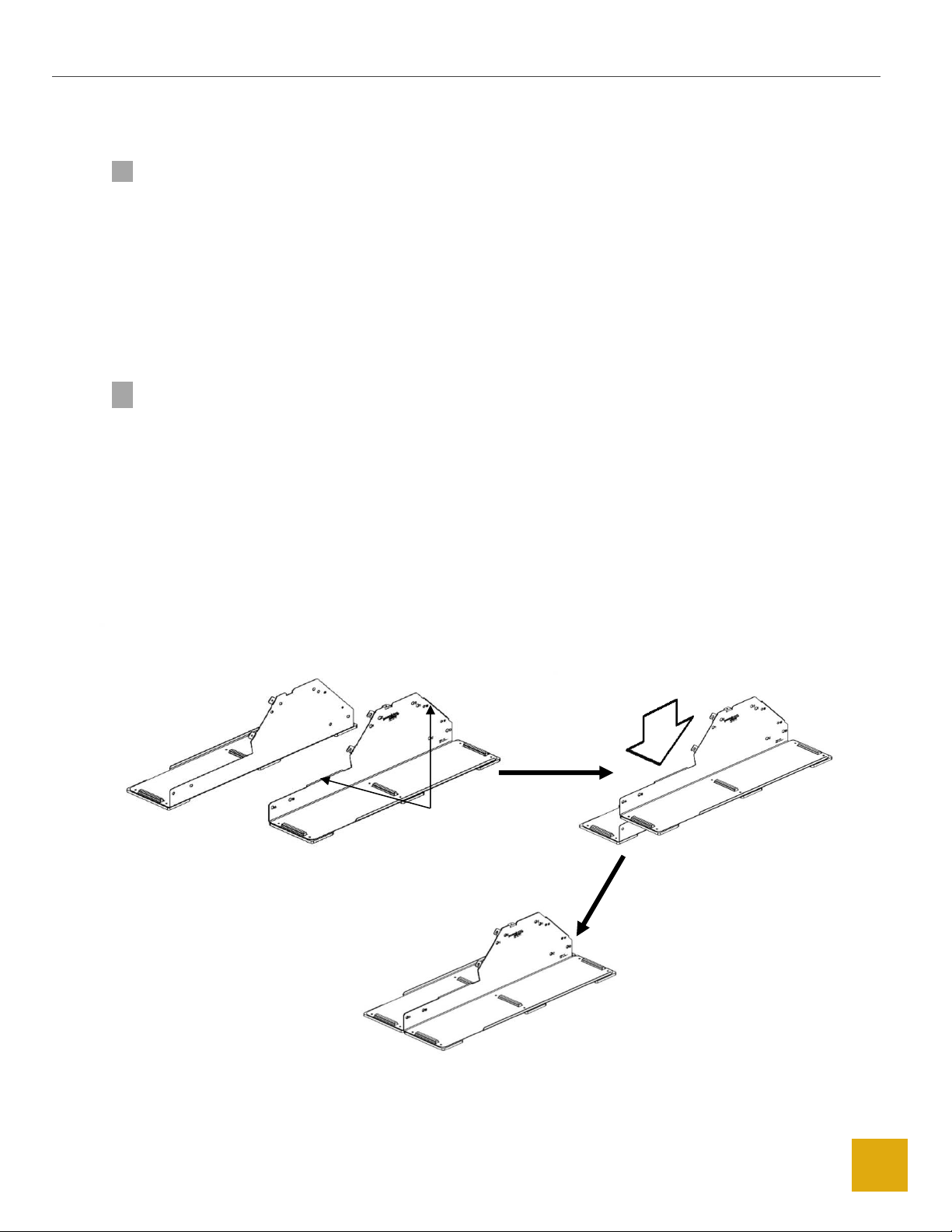
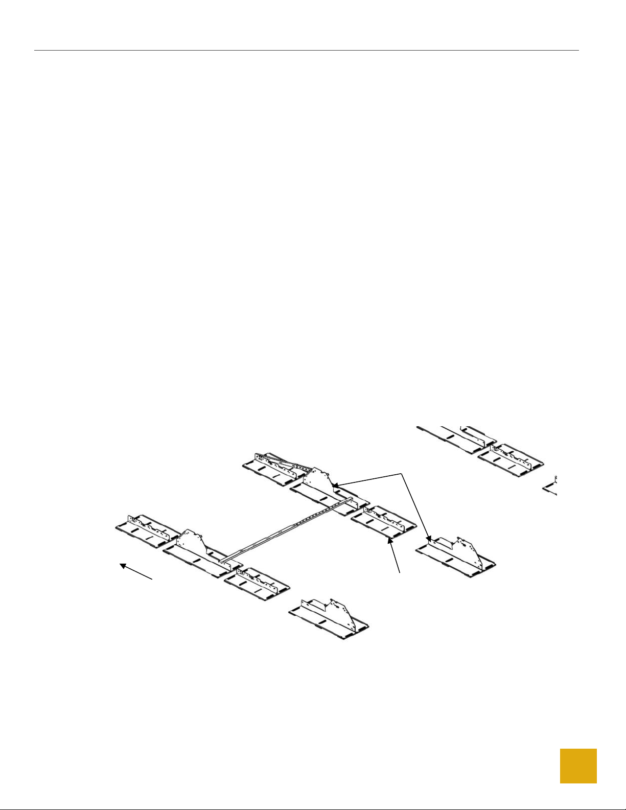
6. Pick a starting corner on the North West end of the array and place Supports as shown below in
Figure 3. The first East West support should be laid out with the high end to the West and the
low end to the East
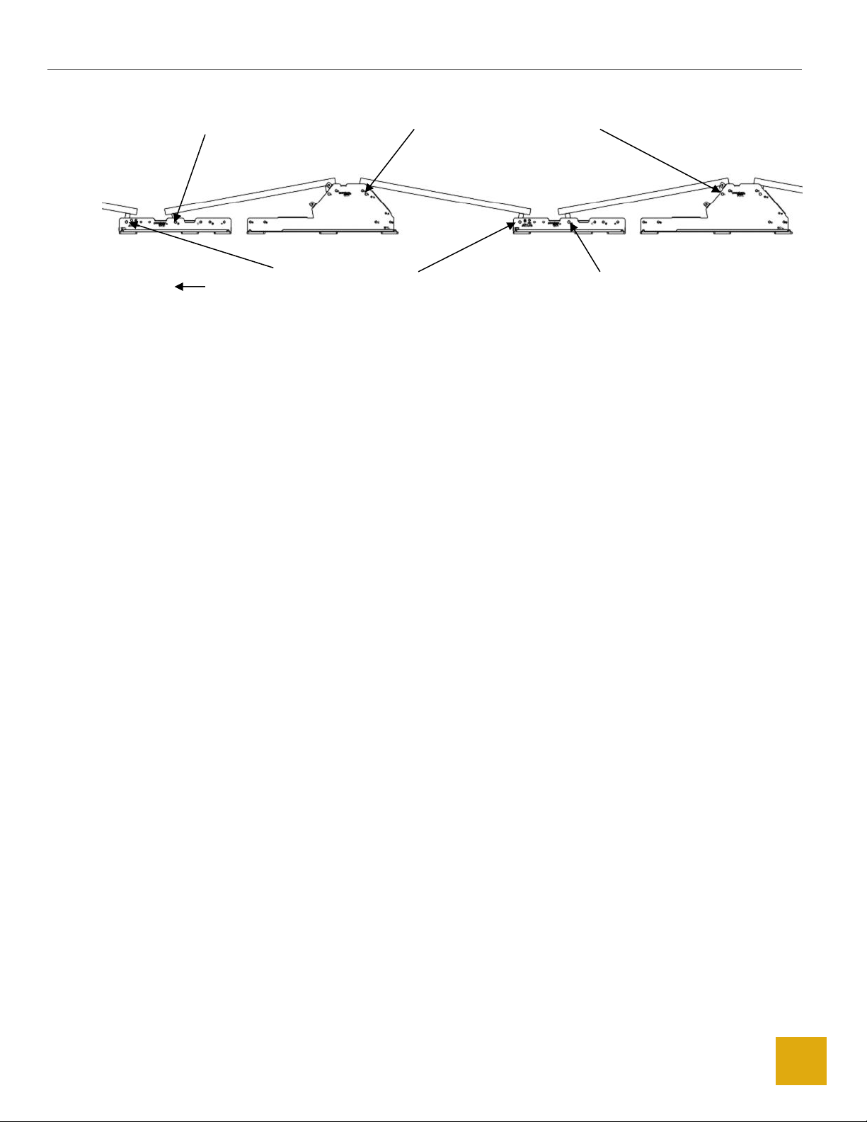
7. Each additional East West Supports will be laid out with the low end to the West and high end to
the East (Figure 4, Figure 5). PanelClaw recommends starting the array in a corner with low
complexity and moving outwards in a direction that best suits the individual array you are
building (e.g. rows and columns with the least number of interruptions/breaks).
Note: Supports without the optional integrated roof protection pad ensure that a proper roof
protection pad is installed. Center the pad under the Support such that the roof protection pad
extends beyond the edge of the Support by an equal amount on all sides (E-W and N-S).
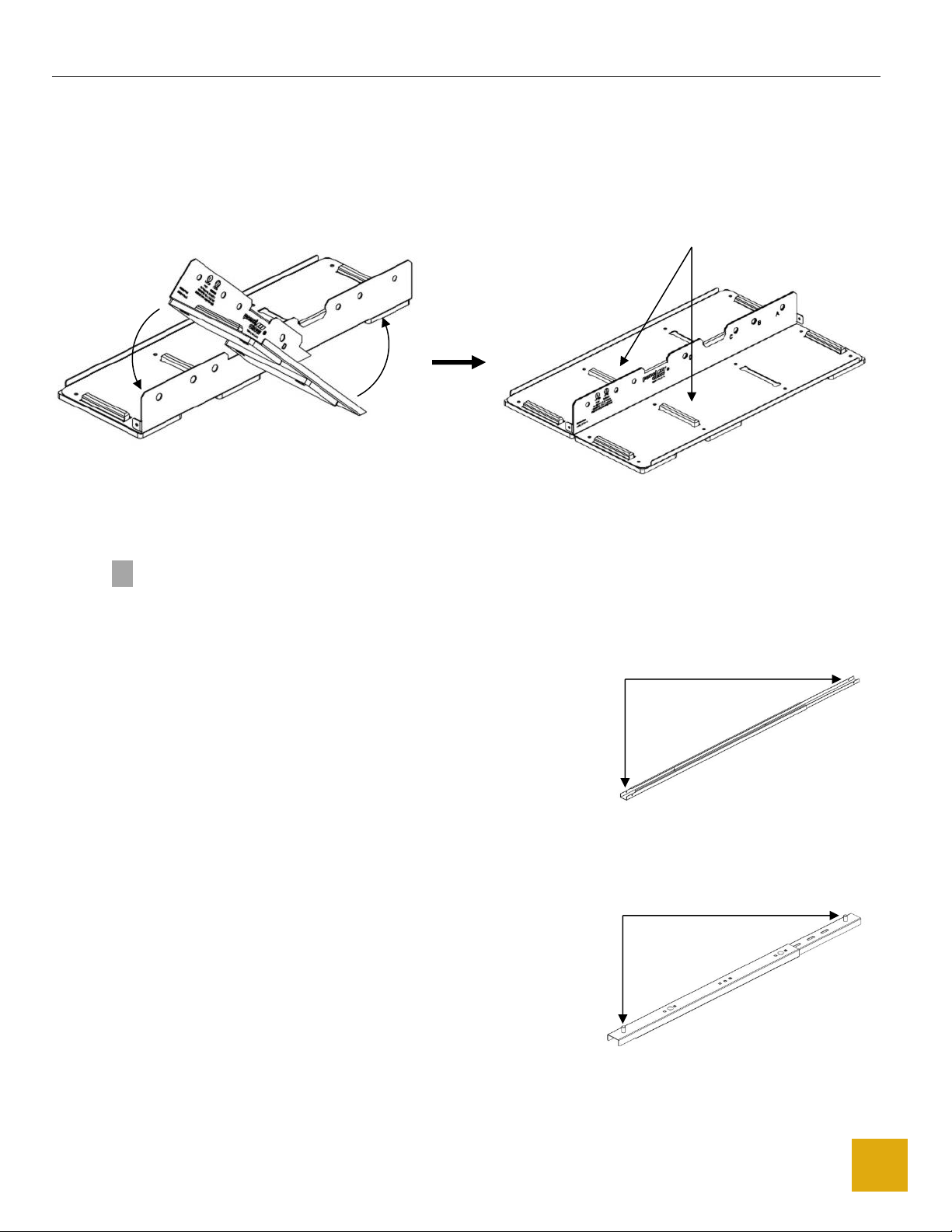
8. Use the properly configured Spacer Stick - A (the longer stick) to position the Supports
apart in the North South direction. Place the notch in the Spacer Stick - A, over the low
end of the Support at the edge of the array and position the Support directly to the
North or South (depending on build direction) so that the notch at the other end of the
spacer stick fits over the low end of the adjacent Support.
9. The distance between Supports in the East/West direction is set using the Spacer Stick - F. The
3/8” studs in the Spacer Stick are placed in the proper Claw mounting hole of a Low Support and
an East West support to properly space out supports. This process can be continued to lay out
the remainder of the array. To determine the proper holes to use with the Spacer Stick on the
high and low end of the Support for this array, please refer to the Ballast Drawing
(typical examples shown in Figure 4,Figure 5 and Figure 6).
Figure 3 Support Positioning West Side
Note Orientation
Note Positioning
West

Polar Bear East/West 10 Degree Installation Manual
9910022 Rev A
9
Figure 4 Completed Support Assembly West Side
Figure 5 Support Positioning Middle
Note
Orientation
Note Positioning
West
Position 1 (Standard or Multi-piece
Claws) or 2 (Long Claw) on High Side
(Note Supports Orientation)
Position “A” on Low Exterior
Side (East Or West Side)
Position “A” (Standard or Multi-piece
Claws) or “B” (Long Claw)
(Note Support Orientation)
Position “D”
(Note Support Orientation)
West

Polar Bear East/West 10 Degree Installation Manual
9910022 Rev A
10
Figure 6 Completed Support Assembly Middle
10. Place ballast on each support based on Ballast Layout Drawing. Each Support will accommodate
up to six Solid Cap Concrete blocks as ballast (not provided). Each block has nominal dimensions
of 4” x 8” x 16” and nominal weight of 26 lb. (11.8 kg). Blocks of various weights may be used in
advance consultation with PanelClaw’s engineering department. Various possible Ballast Block
configurations are shown below (Figure 7).
Note: Blocks should not be stacked on top of each other.
Position 1 (Standard or Multi-
piece Claws) or 2 (Long Claw) on
High Side
Position “A” (Standard
or Multi-piece Claws )
or “B” (Long Claw)
(Note Support
Orientation)
Position “D”
(Note Support
Orientation)
Position “D”
(Note Support Orientation)
Wes
t

Polar Bear East/West 10 Degree Installation Manual
9910022 Rev A
11
Figure 7 Ballast Layout
Step 3: Attach Claws to Module
PanelClaw offers three Claw options to accommodate different frame types, Standard (Claw I), Multi-
piece (Claw III), and Long (Longitudinal). The following directions are for the Standard Claw (Claw I), for
Multi-piece and Long Claw mounting instructions please see Appendix A.
1. Place a PV module face down on protected work surface and place a Claw over the module
frame flange on the short side of the module
Two-block configuration
Three-block configuration
Six-block configuration
Five-block configuration
Four-block configuration
One-block configuration
(Low Support)
Along North and South edges only
Two-block configuration
(Low Support)
Along East and West edges only

Polar Bear East/West 10 Degree Installation Manual
9910022 Rev A
12
2. Slide to the corner and tighten the 3/8-16 x 1.0” 18-8 hex head cap screw between 18 and 20 ft-
lb (24.4-27.1 N-m). Ensure that the Claw is seated up against the flanges of both the long and
short sides of the module as shown in Figure 8 below.
3. Each module must be fitted with the appropriate Claws. The module is now ready to be
attached to the Supports.
4. At this point, it is a good time to prepare the module cables for connection per the module
manufacturer’s specifications and install the module grounding mechanism (not included) per
the module manufacturer’s specifications if necessary (see Step 5: Electrical Grounding, to
determine array grounding requirements).
Figure 8 Claw Attachment
Step 4: Mount Modules to Supports
Begin attaching modules to Supports moving from North to South (or South to North) starting at the
Southwestern (or Southeastern) most corner of the array and moving East/West as each row is
completed.
For the steps below, assume the Southwestern most corner is the starting point.
1. Attach the module to the inside of the first two Low Supports, by inserting a 3/8-16 x 1.25” 18-8
hex head cap screw through the hole in the Claw and the Support. Please refer to the Ballast
Layout Drawing for the proper hole choice, “A” or “D” (default) or “B” and “D” (long claw) on the
low Support. Ensure that the hex head cap screws are inserted into the East/West Support
mounting holes so the threaded end of each hex head cap screw faces the next Support to be
installed (to the North or South). A 3/8-16 serrated flange nut should then be finger tightened
on the Eastern (or Western)-most Support only to initially secure the module (Figure 9).

Polar Bear East/West 10 Degree Installation Manual
9910022 Rev A
13
Figure 9 Attach Module to Low Support
2. Tilt the module back and attach the Claws to the high end of the East/West Support by inserting
a 3/8-16 x 1.25” 18-8 hex head cap screw through the hole in the Claw and the Support (Figure
10). Refer to the Ballast Layout Drawing for the proper hole choice, “1” (default) or “2” (long
claw) on the high end of the Support.
3. Ensure that the hex head cap screws are inserted into the Support mounting holes so the
threaded end of each hex head cap screw faces the next Support to be installed (to the East)
(Figure 10 and Figure 11).
Figure 10 Tilt Module to Attach East/West Support
PV Module
Claw
High End
East/West Support
Exterior Low Support
Serrated Flange 3/8-16
Hex Nut
3/8-16 x 1.25 Hex Head Cap Screw

Polar Bear East/West 10 Degree Installation Manual
9910022 Rev A
14
Figure 11 Tilt Module to Attach to East/West Support
4. Secure Claws to Supports using the 3/8-16 serrated flange nuts. The recommended torque is 28-
30 ft-lb (37.9-40.7 N-m).
5. Continue building the array from North to South (or South to North) by bringing the next
module into place.
a. The bolts on the Northern (or Southern) sides of the array are already in place from
the prior module mounting.
b. Add bolts to the claws and supports that do not have bolts.
c. Secure the bolt connecting two claws and a Support using the 3/8-16 serrated
flange nuts.
d. At the last module in a row or column, ensure that the bolt attaching one claw and
support are secured using the 3/8-16 serrated flange nuts.
e. Connect the module to module wiring.
Repeat this process until all modules are mounted.
Step 5: Electrical Grounding
Please consult with national and local building code(s) for complete grounding requirements for your
installation.
The Polar Bear mounting system is UL and ETL listed to UL 2703 (Rack Mounting Systems and Clamping
Devices for Flat-plate Photovoltaic Modules and Panels). Polar Bear mounting systems enable installers
using modules included in PanelClaw’s UL 2703 listings to quickly and easily establish UL/ETL-certified
electric bonds between all connected array components, including modules and mounting system
components, without the use of additional grounding devices, e.g. ground lugs and copper wire.
Multiple strings with a combined fuse rating of up to 125 amps can be grounded via a single ground lug
acting as a Grounding Electrode Conductor (GEC). When grounding devices are installed according with
the approved methodology and capacity below, the connections described above meet all the
requirements outlined in NEC 690.43.

Polar Bear East/West 10 Degree Installation Manual
9910022 Rev A
15
All PanelClaw module mounting attachments (“Claws”) are certified as recognized components under UL
2703 for module-to-module and module-to-mounting system electric bonding. For projects using
modules not currently included in PanelClaw’s UL 2703 listings, additional approvals from the module
manufacturer and the relevant permitting authority may be necessary to utilize the UL 2703 electric
bonding and grounding method below.
Additional information regarding UL 2703 and the specific modules included in PanelClaw’s UL and ETL
listings can be found in the PanelClaw UL & ETL Overview (UL 2703) document (available at
www.panelclaw.com). For modules that are listed, please follow the instructions. For unlisted and
unapproved modules follow the grounding instructions in Appendix E.
Electrical Grounding Instructions –UL2703 Compliant
Supports within the array are required to be electrically bonded to other DC grounding paths via the use
of a compatible UL 467 listed grounding device acting as a GEC and either #8 or #6 AWG Cu bonding
jumpers.
1. First determine the quantity of strings that a single bonding jumper connection can
accommodate based on the module series fuse rating and bonding jumper size (Table 1).
Note: Verify that all devices used in connecting this bonding jumper can accommodate the
conductor being used.
Table 1 Strings per Bonding Jumper
2. Once the quantity of strings per bonding jumper has been determined, a UL 467 listed
grounding device must be attached to one Support within that group of strings. PanelClaw
provides Supports with a multi-purpose tab to which a grounding device/lug can be attached
(Figure 12). The multi-purpose tab has a hole that is .198” - .208” in diameter.
Module Series Fuse
Rating / DC String Fuse
Rating (A)
Size of Bare Cu Bonding Jumper (AWG)
#8
#6
Allowable Ampacity of Conductor (A)
90
125
Number of Strings per Bonding Jumper
10
9
12
15
6
8
20
4
6
25
3
5
30
3
4

Polar Bear East/West 10 Degree Installation Manual
9910022 Rev A
16
Multi-purpose Tab
NOTE: In some cases a grounding device/lug can come pre-installed, in this case, ensure that the
pre-installed grounding device/lug is listed to UL 467 and can accommodate the size of
conductor being installed. In an array that requires multiple bonding jumpers to satisfy the
capacity requirements, each bonding jumper should be located and installed on a Support
within the group of strings which will be grounded by that jumper.
Figure 12 Install Grounding Device to Multi-purpose Tab
3. Attach a grounding device/lug to the support tab per the grounding lug/device instruction
manual.
4. Once a grounding device/lug has been attached to the Support, a copper bonding jumper must
be installed (as described in the grounding device/lug installation manual), from an acceptable
DC grounded location outside of the array.
5. Verify every independent array section includes at least one grounding device/lug.
Technical Support
To contact PanelClaw Customer Technical Support, call +1 978.688.4900 or email
technicalsuppo[email protected].

Polar Bear East/West 10 Degree Installation Manual
9910022 Rev A
17
Appendix A: Alternate Claw Attachment to Module
Long Claw (Longitudinal Claw)
The Long Claw is used for PV modules that are not compatible with flange clamp style Claws. The Long
Claw attaches at the module mounting holes. Please see the module manufacturer’s installation guide
for screw torque specifications.
Figure 13 Long Claw Detail
1. Place a PV module face down on a protected work surface (
2. Figure 14).
Figure 14 Place Module Face Down
Module Mounting
Holes*
Module Grounding Holes*
(when applicable)
Support Mounting
Tabs
Module Drainage Holes*
(when applicable)
Module Flange Hems
*Hole quantity and locations
will vary per module
Long Side Flange
Short Side Flange

Polar Bear East/West 10 Degree Installation Manual
9910022 Rev A
18
3. Orient a Long Claw parallel to the long side of the module. Ensure that the module flange hems
are facing down and the support mounting tabs are facing outward. Once oriented, lower the
Long Claw until the ends rest on the short side flanges of the module (Figure 15).
Figure 15 Orient and Lower Long Claw
4. Continue by sliding the Long Claw toward the long side flange of the module until the hems slide
past the module flange and the module mounting holes are aligned (Figure 16).
Figure 16 Lower Long Claw onto Short Side Flanges
5. Secure the Long Claw with the hardware provided, ensuring that the bolt is inserted from the
underside of the flange and facing up (Figure 17 and Figure 18). Torque the hardware to the
module manufacturer’s specifications.
Module Flange Hems Down
Support Mounting
Tabs Out

Polar Bear East/West 10 Degree Installation Manual
9910022 Rev A
19
Figure 17 Install Hardware
Figure 18 Cross Sectional Detail of Installed Long Clamp
Long Claw
Long Side Flange
Bolt
Nut
Top Side of Module

Polar Bear East/West 10 Degree Installation Manual
9910022 Rev A
20
6. Repeat Steps 1 through 4 for the other side of the module (Figure 19). The module is now ready
to be attached to the Supports. At this point, it is a good time to prepare the module cables for
connection per the module manufacturer’s specifications and install the module grounding
mechanism (not included) per the module manufacturer’s specifications if necessary (see Step 5:
Electrical Grounding, to determine array grounding requirements).
Figure 19 Completed Long Claw Installation
7. Attach the module to the inside of the low end of the first two Supports by inserting a 3/8-16 x
1.25” 18-8 hex head cap screw through the hole in the Claw and the low Support. Please refer
to the Ballast Layout Drawing for the proper hole choice, “A”, “B” or “D”. Ensure that the hex
head cap screws are inserted into the Support mounting holes so the threaded end of each hex
head cap screw faces the next Support to be installed. A 3/8-16 serrated flange nut should then
be finger tightened on the array perimeter Support only to initially secure the module (Figure
20).
Tilt the module back and attach the Claws to the high end of the Supports by inserting a 3/8-16 x
1.25” 18-8 hex head cap screw through the hole in the Claw and the Support (hole marked “2”).
Ensure that the hex head cap screws are inserted into the Support mounting holes so the
threaded end of each hex head cap screw faces the next Support to be installed (Figure 20).
Table of contents
Other PanelClaw Inverter manuals
Popular Inverter manuals by other brands

FujiFilm
FujiFilm FRENIC-Mini instruction manual

Hobart
Hobart TM416 Operation and maintenance instruction manual

Generac Power Systems
Generac Power Systems PWRcell X7600 Series owner's manual

Clenergy
Clenergy PV-ezRack installation guide

Atlas Copco
Atlas Copco QAS366 Gd USA instruction manual

SMA
SMA SUNNY BOY STORAGE 3.8-US installation manual

A-TS TECHNOLOGY
A-TS TECHNOLOGY DT100-2S0004G user manual

Vollmer
Vollmer 44114 Operation manual

Xima
Xima L100 user manual

Carel
Carel Power + PSD1 Series Installation guidelines

Northern Lights
Northern Lights L944D, M944W, NL944D2, M30CW, M944T, NL944T2, and... Operator's manual

Samlexpower
Samlexpower PSE-24100A owner's manual