Panjing3D PJII User manual

1
The User Manual of PJII 3D Printer
Please read this user manual carefully before using this product.

2
Overview
Thank you for using the 3D printing products of Panjing 3D Technology Co.,
Ltd.
The design concept of PJII 3D Printer is elegance and versatility. Even if you
have never used 3D printer, you are able to create your favorite model easily only
with a touch screen.
The product line uses internationally leading FDM technology with ABS, PLA
and other thermoplastic plastic materials in order to perfectly reveal 3D design. The
principle of the printer is to melt by high temperature and extrude printing material,
then rapidly solidify it after modeling to make sure the printed model is strong and
durable. The product line is widely used in education, mechanical design, household,
art creation and other fields.
Important Notice
Operating Temperature of Nozzle
100℃~230℃
Best Ambient Temperature
18℃~40℃
Electric Hazard Sign: It warns you to avoid the
possibility of electric shock injury.
High Temperature Sign: It warns you not to touch hot
equipment components.

3
PJII Printer Body
1. Left Nozzle
2. Printing Plate
3. Display Screen
4. Right Nozzle
5. Power On/Off Button
6. SD Card
7. USB Interface
8. Filament Spool Mounting Hole
9. Power Adapter Hole
10. Power Interface
11.The Filament Feeding Hole
12. Filament Feeding Press Block

4
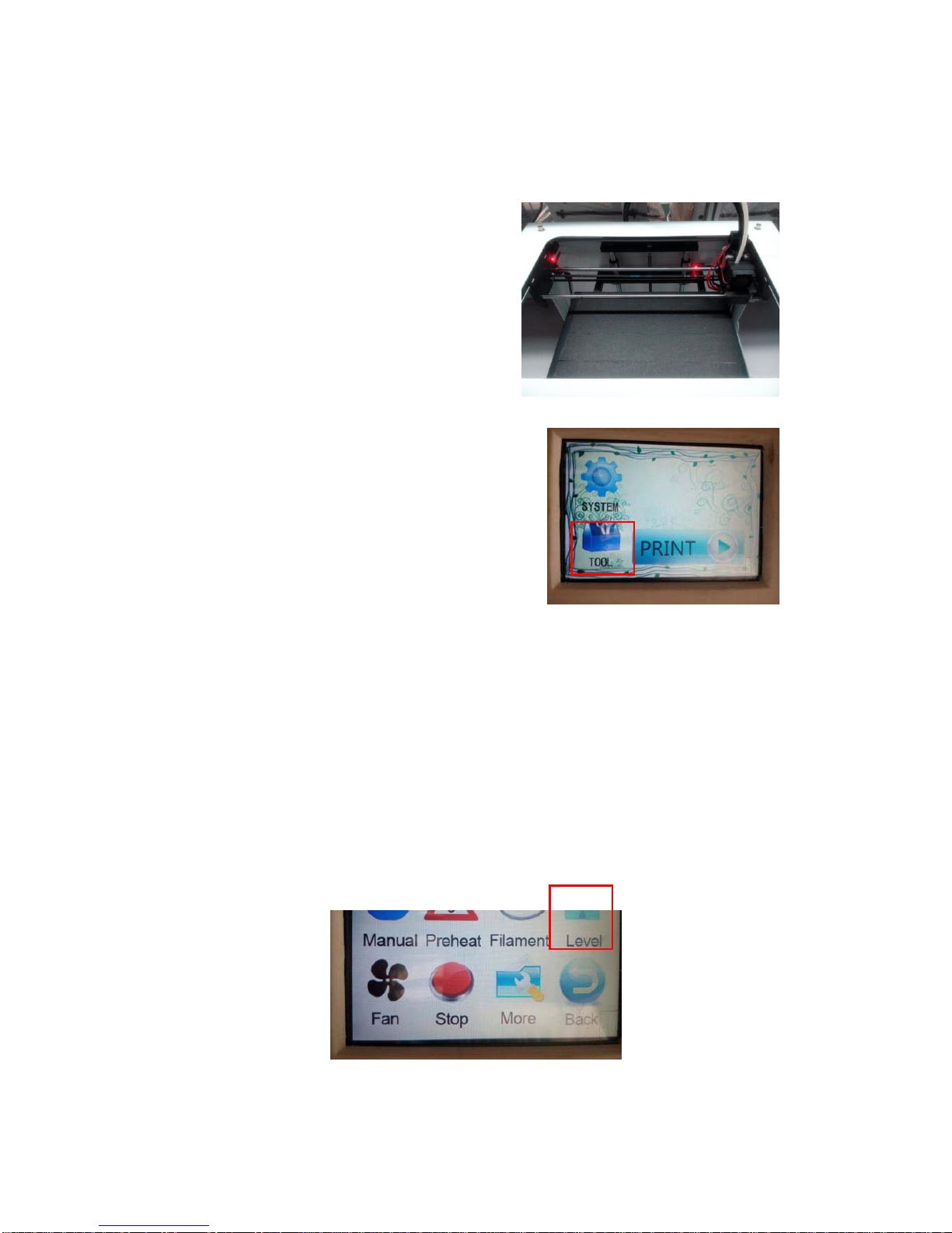
Printer Platform Leveling
1. Plug in the power cord and turn on
the power switch. Then press and
hold Power On button for 3 seconds
till starting up.
2. Click Tools option on the display
screen.
3. Select and click the Leveling option on the display screen, and click NEXT.
Wait till the printing nozzle stops, then manually adjust the screw which is closest to
the nozzle until the distance between all locations of the platform and the nozzle is
the thickness of one piece of A4 printing paper. After the proper adjustment, click
NEXT to wait till the printing nozzle stops, and continue to adjusting it. After
adjusting four corners in turn, the platform leveling is complete. (If the nozzle is too
close to the platform, the filament feeding is likely to be affected. If the distance is
too far, it easily causes that the filament feeding cannot stick to the platform)

5
The Installation and Replacement of Filament
Please properly install the Accessory—Filament spool Axis, and correctly
install the Filament Spool on the Filament Spool Axis. (Pay attention to the direction
of filaments, and please be sure not to install it backwards! Also please make sure
there is no knot or lag in the filament.)

6
Pull out the filament from the filament spool, and cut out a bevel gap at the top, then
lead the end of the filament to the motor in accordance with the direction of arrow in
the following Figure. Press down the Filament Feeding Press Block, and introduce the
filament into the extruder.

7
Preheating 1. After startup, click Tools option on the display screen.
2. Select and click Filament.
3. Select Install Filament Nozzle, click the Temperature Display, which indicates it
starts heating when it turns red.
4. Wait for 1-2 minutes till the temperature of nozzle reaches the preset temperature.
Click Install Filament Feeding option.

8
5. Clicking on STOP when the filament is extruded out of the nozzle.
Note: If there are filaments in other colors being extruded at the beginning of filament
feeding, they are the remaining filaments inside the nozzle during the factory test. It
belongs to the normal condition.

9
Installation of ChiTuSlicer Software
ⅠOpen the installation file of ChiTuSlicer in SD card, and click Install.
ⅡEnter the software installation interface and click Next.
ⅢSelect the installation location, and click on Install.
ⅣAfter the software installation is finished, click on Close.

10
Basic introduction of ChiTuSlicer software
Open the Choose Machine Model option of ChiTuSlicer software to select the model
settings. Set up the parameters according to the corresponding machine model data in
the machine model parameter file in SD. (This step is not needed when WiFi online)

11
Click and open File icon.
Open the designated STL file; after we choose the designated file, our chosen file
model will display on the right side of software;
Click on the model, Remove Model and other options will display.

12
Right-click on the model, then three icons will appear at the left corner.
Select “Rotate” to rotate the model;
Select “Scale”, the model can be scaled;
Select “Mirror” to mirror the model;
ChiTuSlicer software offers a variety of advanced observation methods. These
methods are hidden in the button at the upper-right corner. Press this button, you can
see an View mode menu.

13
Currently, we are using the default Normal mode. You can also select Overhang mode,
Transparent mode, X-Ray mode, and Layers mode.
Under the Overhang mode, the overhanging parts of 3D model will be shown in red.
In this manner, users can be allowed to easily observe the problematic parts of the 3D
printing model. If necessary, these problems can be solved before printing.
Under the Transparent mode, we can not only observe the front of the model, but also
observe the opposite of model as well as the internal structure. In particular, internal
structure plays a crucial part in 3D printing. Therefore, please be sure to properly
observe it before printing. For our model, as you can see, there is no any special
configuration inside.
Next is the X-Ray mode. Similar to Transparent mode, X-Ray mode can also be used
for viewing the internal structure. The difference is that under the X-Ray mode, the
structure of the object’s surface is ignored. Although you cannot see the surface of 3D
object, the internal structure can be appeared more clearly, which is easy for viewing.
Finally, the Layers mode is rather important. Layers model is actually closest to the
formal 3D printing process. Under this mode, we can display the entire 3D model by
layer. Through the right side of the slider, you can observe each layer separately.

14
In the Figure above, we are observing the condition of the 58th floor. As shown in
Figure, the outermost part in red represents the shell of model. The following green
part remains one section of the shell, but it is not directly exposed. The middle part in
yellow is filling, which is used to constitute the central part of solid object. Armed
with this information, 3D printing plan of each layer which is planned out after the
Cura slicing can be understood more properly and intuitively. If the problem occurs, it
can be easily positioned and solved.
After the model is loaded, 3D image of loaded model can be seen immediately in the
main window. Meanwhile, at the location marked with a red box at the upper-left
corner of the window, you can see a progress bar is on the move. Soon, when the
progress bar reaches 100%, time, length, and gram can be displayed and the save
button (Save Gcode) becomes available. As shown in Figure:

15
The fast advancing process of the progress bar just now is the working process of
ChiTuSlicer software slicer. When the slicer operating is finished, 3D printing time (2
hours and 37 minutes), required length of the plastic filament (9.08 meter) and gram
(27g) are all calculated. Also, we can use the Save Gcode button to save the
slicing result as the gcode file. Save it in your SD card, then insert the SD card
into the printer. And the printer can print this model.
When you need to adjust the printing parameters, you can click on Setting button
at the upper-right corner, then a Print Setting window will pop up.

16
Printing quality
Slice thickness indicates the height of each layer. This setting affects printing speed
most directly. It is obviously that the smaller the slice thickness is, the longer the
printing time is, and relatively good printing accuracy can be obtained. Wall
thickness is thickness of the plastic casing generated around it by a solid 3D model in
the 3D printing process. Of course, except for the casing part, all parts are filled with
latticed plastic grids. Wall thickness to a large extent influences the solidity of 3D
printing models. Open Fallback means whether to draw back the filament at two
printing intervals to prevent excessive filaments to be extruded at the intervals, or else
it may lead to wiredrawing and affecting printing quality.
In the bar of the quality, two options, both slice thickness and wall thickness, are
closely related to the diameter of extruder of 3D printer. The wall thickness should be
set as the multiple of diameter of extruder, while slice thickness cannot be higher than
80% of diameter of extruder. If your settings do not meet it, the software will set the
input box in yellow to prompt the user. If you find any problem in the diameter setting
of the extruder, you can jump to the bar of the Machine Model at the bottom of
window to set the nozzle diameter and come back.
Filling
The bottom/top thickness is similar to the wall thickness, so it is recommended that
this value shall be close to that of wall thickness, and shall be the multiple of slice
thickness. Filling density refers to the density of latticed plastic filler inside the solid
3D model. This value is independent of the appearance, the smaller the value is, the
more materials and printing time it saves. But the strength will be affected to some
extent. Generally speaking, 20% filling density is also enough.
Speed and Temperature
The printing speed refers to the amount of the plastic filament extruded per second.
Under general settings, this value can be set between 50~60 mm. Because the heating
speed of extruder is limited, the amount of plastic filament which can be melted per
second is limited. When the slice thickness is set higher, only relatively small value
can be selected to meet the limit of total extrusion amount of extruder. When your
settings do not meet the software requirements, the edit box will turn yellow to
remind users that there are problems to be solved. In the following, three settings
related to temperature are relatively simple. Printing temperature is set according to
the filament temperature of first nozzle. The temperature of second nozzle is set
according to the operating temperature of second filament. The heated platform
temperature is rather easier to set up, it can be set at 50 degrees to have the printed
PLA firmly adhered to the platform. It can be set at 110 degrees when printing ABS to
lessen the warped edges of model.

17
Support
Firstly, as for the support types, there are choices among no support, extending to the
platform support and all overhanging support. Extending to platform support is the
type of support which is only set to the model part that adheres to the platform. All
overhanging support refers to establishing support for suspended parts inside the
model. Adhesion platform means whether to strengthen the adhesion feature
between model and printing platform, and the choice No refers to printing 3D model
directly on the printing platform. If you want to solve the problem of warped edges,
you may try to select the edge, which will print the hat brim around at the first layer to
allow the 3D model to be stuck more firmly with platform. Also, removal is relatively
easy when the printing is complete. If it still does not work, you can select the base,
which will print a high seat under the 3D model. It can guarantee that the 3D model is
firmly stuck to the heated platform, but it is not so easy to remove. In terms of
Dual-Nozzle Printing Support, user can select among Both, First Nozzle and Second
Nozzle. For the directly stripped support, any nozzle is appropriate, so Both can be
selected. If one kind material is rather expensive, you can choose another material to
print support (this will lead to more switching among nozzles). When you print
support with the water-soluble material, you should choose the Second Nozzle (Left
Nozzle).
Support · Edge and Base
Even if they are added, they will not be displayed in general 3D view. If you want to
see results, you need to switch to Layer mode.
Dual nozzles
Wipe and Prime Tower refers to printing a salvage erasing tower at the mean time of
Double-Nozzle printing (it is printed upon the switches of nozzles at each layer of
model, erasing the salvage of another nozzle before the current nozzle starts printing).
Overflow protection is to print a thin wall outside the model. This thin wall can erase
some unwanted leakage during the dual-nozzle printing.
Filaments
For the bar of Supplies, the diameter of Supplies should be assigned, it should be
changed to 1.75 according to the diameter of printer supplies. For the bar of Flow, the
percentage of the amount of extruded plastic to the default value can be set. If the
printer is already in a good correction, it is OK to fill it with 100%.
Machine Model
Nozzle Diameter can be set according to the actual size of the nozzle.
Next, we enter the Advanced Slice Setting page.

18
Fallback
It can set speed and distance of fallback to reduce wiredrawing of printing model and
enhance the smoothness of surface of printing model. Double nozzles switching
fallback is to control the leakage in double-nozzle printing.
Printing quality
It has something to do with the bar of printing quality in the Basic Settings, but
generally it does not need to be modified. The initial slice thickness can be set as the
slice height. The reason of separating it out is that actually in special cases slice height
can be set at a very small value (such as 0.05mm). However, if the first layer is set in
the same way, it cannot be stuck to the hotbed properly. For this reason, the initial
slice thickness can be assigned individually. The filament width of initial slice is also
related to the adhesion between 3D printing object and the hotbed. In some cases, it
can be assigned a value higher than 100% to strengthen the adhesion degree. Base
removal is used for some 3D objects in the irregular shapes. If there are limited
connection points between the bottom of object and the hotbed, they will be unable to
stick with each other. Then this value can be set at a value higher than 0. In this
manner, the 3D objects will be cut from the bottom, so it can be stuck to the hotbed
more firmly. Finally, Double Extruding and Overlapping is only valid for
double-nozzle 3D printer. If there is a little overlap of the content extruded by two

19
nozzles, better results can be obtained. It is usually appropriate that these maintain the
default values.
Speed is used to specify the operating speed of printer at various stages of 3D
printing.
Refrigeration is used to control parameters of the cooling fan. It is rarely seen that
these two bars need to be modified, so it is appropriate to maintain the default value.
。
SD Model Printing
Please make sure that the SD card is inserted into the side slot, and turn on the power
switch to energize the equipment. The SD card we offer to you as the standard
equipment includes the test model. You can also add GCode model files which is
sliced by software by yourself and print it in the SD card.
Click on Print on the interface, and select the GCode file of the model which is
expected to be printed from SD card, then it starts printing automatically after the
temperature rises to required level.

20
Wireless WIFI Connection
WiFi connection computer need to have the wireless network adapter capability, and it
should be online with the printer via the wireless router. The printer and computer
must be connected to the same wireless router.
(SD card must be inserted into the printer at the time of WiFi connection)
Wireless WIFI connection method 1: The direct connection to hotspot,
one-to-one
Attention: For direct connection to hotspot, the computer is unable to connect to the
Internet.
1. Turn on the printer’s power switch, start the printer to enter the standby mode.
Click on System option on the touch-screen, then go to the next screen and click
on the WIFI option. Check the name and password of WiFi of the machine.
2. On the computer, select the name of the printer’s WiFi and connect.
Table of contents