Matrox Altiz User manual

Using multiple Matrox Altiz units
Application Note
Page 1 of 8
Preliminary
December 7, 2020
Overview
This document will provide information on how to mount and setup multiple Matrox AltiZ units to
perform synchronized acquisitions. The Matrox AltiZ units can be placed at different heights, positions
over the conveyor, or in parallel to increase the Field of View (FoV) along the conveyor’s width. The FoV
between synchronized Matrox AltiZ units can overlap or can be staggered.
If there is an overlap between the FoVs, you will need to shift the exposure times so that the laser from
one Matrox AltiZ unit does not interfere with that of the other.
Hardware configuration
Star configuration
In this configuration, the first Matrox AltiZ unit receives and processes an external input signal (for
example, an encoder or a proximity sensor), which initiates its own line and frame trigger. A Sync signal
can be set up to trigger the line acquisitions of the additional Matrox AltiZ units in the Star
configuration. The Sync Signal is typically the Exposure Active signal of the first Matrox AltiZ unit.

Using multiple Matrox Altiz units
Application Note
Page 2 of 8
Preliminary
December 7, 2020
In our example, we connected AUX_OUT4 of ALTIZ 1 to AUX_IN0 of ALTIZ 2 and 3. Other input and
output pins can be used, as long as they are free.
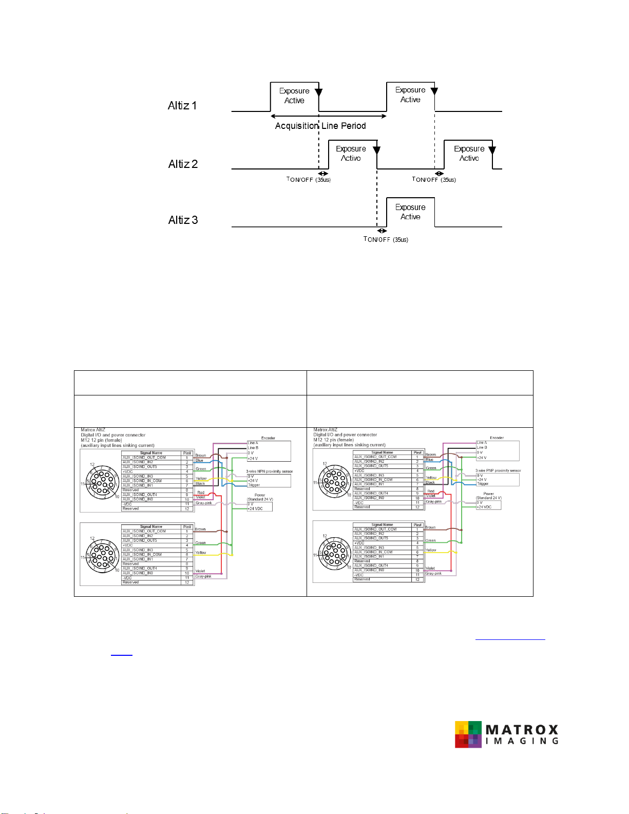
In the case of an overlap between the FoVs, the exposure window of two adjacent AltiZ units must be
offset to avoid artifacts introduced by the neighboring laser. Line acquisitions on ALTIZ 1 and ALTIZ 3 are
triggered simultaneously, and then ALTIZ 2 is triggered when the exposure of both ALTIZ 1 and ALTIZ 3
turns OFF.
The ON to OFF response time is 35µs and the OFF to ON response time is 55µs, as outlined
in the Electrical Specifications section of Appendix B in the Installation and Technical Reference manual.
This results in a duration limit for the exposure time:
100µ𝑠 < 𝐸𝑥𝑝𝑜𝑠𝑢𝑟𝑒 𝑇𝑖𝑚𝑒 < 𝐴𝑐𝑞𝑢𝑖𝑠𝑖𝑡𝑖𝑜𝑛 𝐿𝑖𝑛𝑒 𝑃𝑒𝑟𝑖𝑜𝑑 − 𝑇𝑂𝐹𝐹/𝑂𝑁
2
With more than two AltiZ units, a programmable delay of min 20µs (TOFF/ON-TON/OFF=20µs) is required
between the end of exposure on AltiZ 1 and the exposure start of AltiZ 2.

Using multiple Matrox Altiz units
Application Note
Page 3 of 8
Preliminary
December 7, 2020
Daisy chain configuration
In this configuration, the Sync signal is transmitted sequentially from one Matrox AltiZ unit to the next.
In the case of an overlap between the FoVs, acquisition for the following AltiZ in the chain is triggered by
the falling edge of the Exposure Active signal from the previous AltiZ in the chain. In the daisy chain
configuration, the exposure is limited to half of the Acquisition Line Period, minus the ON to OFF
response time
100µ𝑠 < 𝐸𝑥𝑝𝑜𝑠𝑢𝑟𝑒 𝑇𝑖𝑚𝑒 < 𝐴𝑐𝑞𝑢𝑖𝑠𝑖𝑡𝑖𝑜𝑛 𝐿𝑖𝑛𝑒 𝑃𝑒𝑟𝑖𝑜𝑑
2− 𝑇𝑂𝑁/𝑂𝐹𝐹
Using multiple Matrox Altiz units
Application Note
Page 4 of 8
Preliminary
December 7, 2020
Connecting the auxiliary input and output lines
Two power configurations allow the current to flow from the AUX_OUT pin to the AUX_OUT_COM pin
(or vice versa) and from the AUX_IN pin to the AUX_IN_COM pin (or vice versa). In one configuration,
the inputs are sourcing current and the outputs are sinking current. In the second configuration, the
inputs are sinking current and the outputs are sourcing current.
Sourcing Inputs - Sinking Outputs
Sinking Inputs - Sourcing Outputs
AUX_IN_COM = +VDC
AUX_OUT_COM = -VDC
AUX_IN_COM = -VDC
AUX_OUT_COM = +VDC
-Connecting AUX_IN_COM and AUX_OUT_COM from multiple Matrox AltiZ units to a single +VDC
and -VDC can be done by using a power distribution block (ex: Phoenix Contact VIP-2/SC/PDM-
2/16)
-The rated current for each AltiZ is 500mA @ 24 V (12 W), as specified in the Electrical
Specifications section of Appendix B in the Installation and Technical Reference manual.

Using multiple Matrox Altiz units
Application Note
Page 5 of 8
Preliminary
December 7, 2020
Software configuration using Matrox Capture Works
Set volume parameters (y and z directions)
To configure the volume parameters Length World, Motion Step World, Size Z World, and Offset Z World,
read the following examples in the Chapter 6 in the Installation and Technical Reference manual.
-Example 1: Quickly performing a single-profile scan with default settings.
-Example 2: Performing a single-profile scan with optimized settings.
-Example 3: Performing a multi-profile surface scan using a constant line (profile) rate
Ensure that SourceSynchronization is set to Synchronize.
Set the encoder and the Line Trigger
To configure the encoder for the first Matrox AltiZ unit, read the Performing a multi-profile surface scan
using an encoder, example 4 of Chapter 6 in the Installation and Technical Reference manual.
AltiZ 1
Once you have set up the encoder on AltiZ 1, perform the following to configure the encoder as a line
trigger:
-Navigate to Trigger Control under Quick Setup Control, and set Trigger Selector
(TriggerSelector) to Line Start.
-Expand Trigger Selector and set Trigger Source (TriggerSource) to Encoder0.
-Set Trigger Mode (TriggerMode) to On.

Using multiple Matrox Altiz units
Application Note
Page 6 of 8
Preliminary
December 7, 2020
AltiZ 2-n
The acquisition for Matrox AltiZ units that follow the first AltiZ in the sequence are triggered differently,
depending on the type of configuration (star or daisy) and the unit's position in the configuration:
- Navigate to Trigger Control under Quick Setup Control, and set Trigger Selector
(TriggerSelector) to Line Start.
- Expand Trigger Selector and set Trigger Source (TriggerSource) and Trigger
Activation (TriggerActivation) with the values from the following table :
Configuration
Star
Daisy Chain
AltiZ 2, 4…
Trigger Source :Timer 0 End
Trigger Activation: Rising Edge
Trigger Source : Line 0
Trigger Activation: Falling Edge
AltiZ 3, 5…
Trigger Source : Line 0
Trigger Activation: Rising Edge
Set Exposure Time
To configure Exposure Time perform the following for every AltiZ in the configuration:
-Under Acquisition Control, expand Source Selector and select Source 0 (Primary). Ensure that
the value in the Exposure Time field is less than half of the value of the Acquisition Line
Period field in the case of an overlap between the Field of Views.

Using multiple Matrox Altiz units
Application Note
Page 7 of 8
Preliminary
December 7, 2020
Set the I/Os
In our example the Sync signal we are using is the ExposureActive signal from AltiZ 1.
The ExposureActive signal is transmitted across the AUX_OUT4 output signal of AltiZ 1 to the AUX_IN0
input signal of AltiZ 2 and to subsequent Matrox AltiZ units. To set the Line Source for our Sync signal,
perform the following:
-Navigate to Digital IO Control and set Line4 under Line Selector
-Expand the Line Selector category and set Line Source to Exposure Active

Using multiple Matrox Altiz units
Application Note
Page 8 of 8
Preliminary
December 7, 2020
Set the delay (star configuration for AltiZ 2, AltiZ 4 …)
If you are using the star configuration, you will need to set a delay for all of the AltiZ units following AltiZ
1. To set a delay, perform the following:
-Navigate to Counter and Timer Control and expand the Timer Selector category, then
select Timer0
-Set the timer duration to the desired delay value (for example, 50us)
-Set Timer Trigger Source to Line 0 (if the Exposure Active signal is transmitted to AUX_IN0)
-Set Timer Trigger Activation to Falling Edge.
Table of contents


