Panther P1 User manual

I n s t r u c t i o n M a n u a l
Panther P1 Dolly System

Foreword
Congratulations to your decision of purchasing or renting your PANTHER P1 dolly.
We are pleased that you made your decision in favor of a dolly, which
combines an economic concept, state-of-the-art technology and many years of
experience in manufacturing camera dollies.
Selected materials, know-how and a solid drive ensure that in practice you have a
wide variety of possibilities, which you will appreciate during shooting.
Your new PANTHER P1 dolly is a high-quality tool giving the creative
cameraman the means for camera shots and drives, which could so far only be
realized with great efforts or not at all.
The PANTHER P1 is a dolly developed by specialists for specialists in order to meet
the expectations of every cameraman or grip.
To ensure that you will love working with your PANTHER P1 dolly and that all
requirements during shooting can be fulfilled considering utmost safety and
reliability, please carefully read this operation manual.
With our best wishes
Andy Fitz
Panther GmbH

Safety hints
1. Do not start operating the dolly until you have read and understood the
operating instruction. All safety hints, information on measures and weights,
as well as on maintenance intervals have to be observed.
2. The Panther P1 dolly may only be operated by competent staff.
PANTHER regularly offers training seminars, in which participants receive a
certificate after successfully completing the training. For further information
and dates please contact us under +49 89 613 900 01.
3. Lifting, swiveling and drive area of the dolly including accessories have to
be kept free in any case. Possible danger of bruises.
The safety zone of ≥ 0,5 m must be kept free in all directions.
4. Please observe that there is a danger of tilting whenever you mount any
equipment on the Panther P1 dolly. Please refer to the load chart.
5. Attention: do not use the dolly on inclined planes or in vehicles.
By means of wheel brakes or other devices the Panther P1 dolly has to be secured
against unintended movements. The subsoil needs to be firm and unyielding.
A minimum payload of 500 kg/m² is required of the subsoil.
6. Repair works should only be executed by the manufacturer or by well-trained
staff. PANTHER is offering training seminars, which can be held according to
agreement. For further information please call +49 89 613 900 30 (Panther
Service Department).
7. When charging batteries, the general VDE guidelines have to be observed. The
dolly needs to be protected against moisture.
8. Make sure that unauthorized personnel can not use the dolly if the dolly is out
of order. If needed take the right measures against a storm.

The Panther P1 Column Dolly
1. Carrying handle 5. Fuse
2. Removable Euromount 6. Handset control with cable
3. Plug for handset control 7. Adjustable column mount
4. Main switch 8. Quick lock battery mount
12
3
4
5
6
7
8

Mechanical Principles
It is useful to understand the Panther P1 Dolly’s mechanical principles, in order to
avoid misusing the dolly. This is why we are noting the most important
characteristics in this operation manual.
Drive
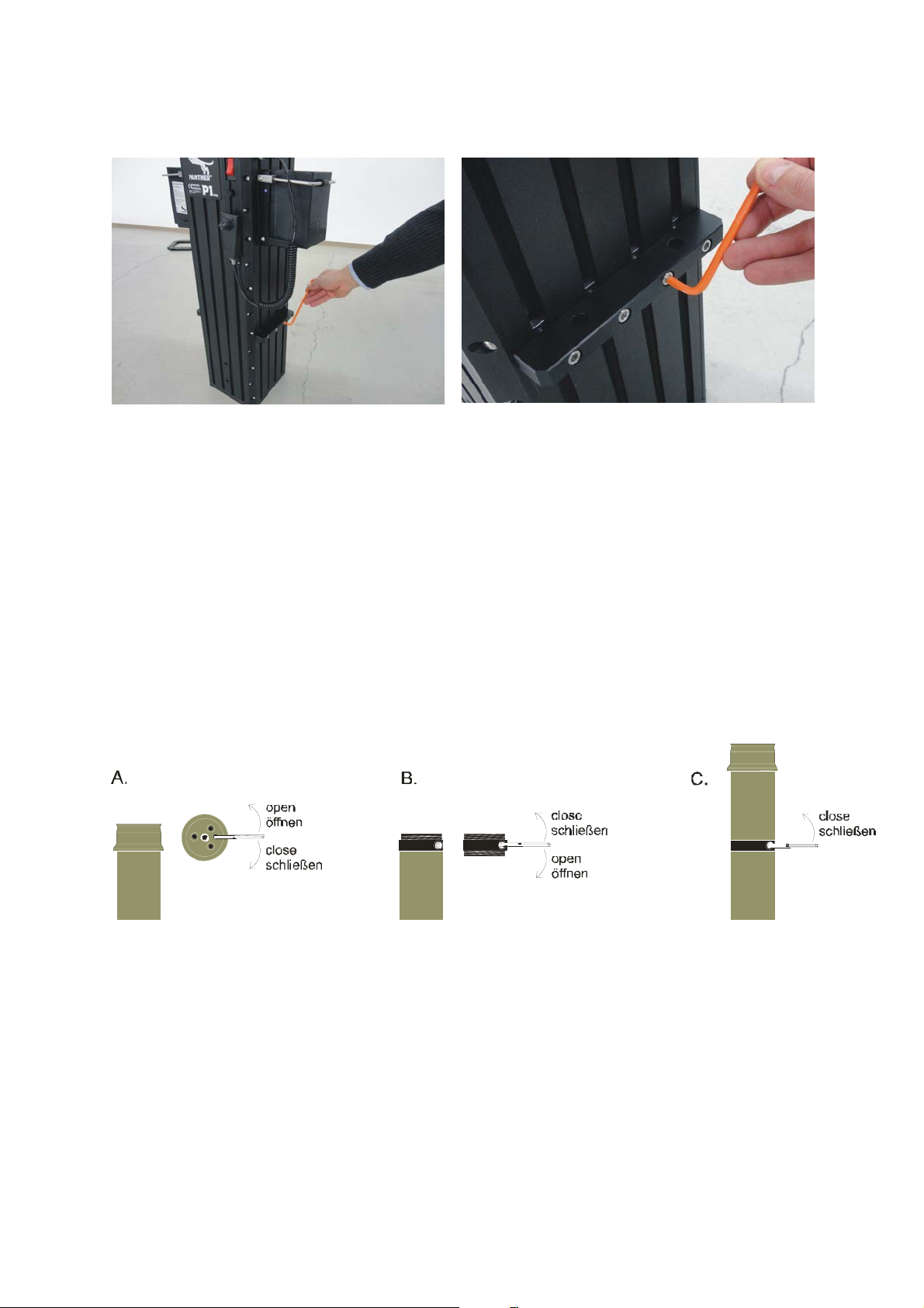
The column is moved up or down by a spindle that is located on the back side
(opposite side of main switch) of the column. This spindle is driven by a motor via a
flat belt. When in stand by operation, the column is held in position by the spindle.
Note:
When in moving operation, the motor, spindle and column tube creates mechanical
noise. This is normal and the result of mechanical friction. Moving the column at
approx. 50% of max. speed, the noise is low enough for normal shooting. If speed
goes up, the noise level rises.
Initial Operation
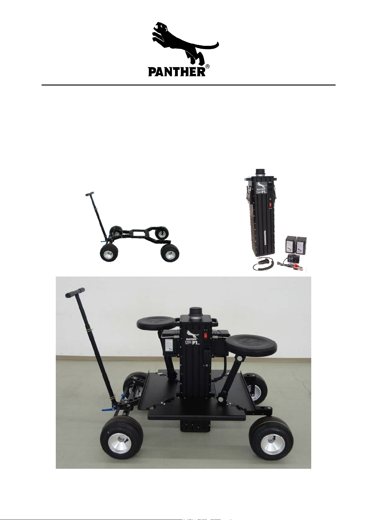
1. Connect batteries to P1 Column as described in „Power Supply“.
Note: Only operate the Panther P1 Dolly with fully charged batteries.
Although the batteries left our warehouse with fully charged batteries, it is possible
that a long transit time/low temperatures caused the batteries to empty. Please
check this before operation.
Fully charge the batteries before first use.
2. The Panther P1 Dolly’s (and accessories) complete lift, panning and movement
range must be cleared before switching on the dolly.
3. Check that the connection handset control to dolly is correct.
4. Switch the dolly on at the main switch.
5. Move the column up or down with the handset rocker switch.
Attention:
The red main switch on the handset control also
serves as an Emergency-Off-Switch!
Column moves down in max. speed if cable
breaks or in case of disconnection.
In that case, switch off column immediately with
“Emergency-Off-Switch”.
The Panther P1 Dolly may only be operated with the original Panther batteries.

Handset Control
Main switch:
The dolly is switched on and off at the main
switch.
It is also used as an „emergency-off-switch“.
Rocker switch:
Move the column up or down with the handset
rocker.
Velcro fastener:
For parking position, the handset control is
attached to the column by Velcro fasters.
Up
Down
Note:
Main switch will shut off (fuse), if current is exceeding the permitted level.
All ramp and speed settings are done via the handset control rocker.
End switches will lower the speed of column approx. 10cm before the upper and
lower end of column lift range is reached.
Observe safety distances especially in use with low rigs etc. If there is any danger of
crushing, switch of immediately the main switch (Emergency-Off-Switch).
P1 Column with platform Dollies (e.g.Twister Dolly)
Dolly Platform
Drive Belt
Motor
Spindle
15mm !
P1 Column
Base Plate
A
ttention!
Attention:
Do not exceed the length of thread in P1 Colum Base Plate (15mm)!
You may damage parts inside the column with connecting screw.

Track operation
P1 Dolly is designed to track on 36cm and 62cm gauge.
The Panther SkateBoard Wheels are designed to track on straight and curved tracks.
The minimum allowed curve diameter is 3m. An extra “curve track wheel” is not
necessary.
Attention:
When operating in offset mode (e.g. low rig), wide gauge (62cm) must be used due to
stability reasons (tilting). The loading chart must be adhered to in all circumstances.
Assemble necessary components in right manner listed below.
36cm Gauge
62cm Gauge

P1 Dolly in tracking mode fully equipped with four platforms, two seats, and
telescopic push bar.
To mount Push Bar use connecting clamp or use 25mm holes in legs.
Attention:
The tracks underneath the dolly must always be laid out horizontally. Tracks and
wedges must be secured against slipping.
A stable underground and underlay must be ensured. It must be able to carry at least
the weight of the complete dolly with accessories and persons.
Ultimate load of underground and underlay material: min. 500 kg/m²
Good underground: Bad underground:
All hard surfaces All soft surfaces
e.g. asphalt (road) e.g. forest floor, sand
Note:
If the dolly is not moved on the track, all four wheels should be locked by
arresting the brakes or other devices (e.g.clamps etc), for safety reasons (especially
when mounting or unmounting accessories).

Load chart
Following loading chart may not be exceeded.
Centric load: Offset load:
Maximum centric load on column: 45 kg (100 lbs).
Maximum offset load: 25 kg (55 lbs) with a maximum reach of 50cm (20´´).
Offset mount on operator side (main switch) only!
Note: Insert column in different direction if offset is needed on other side.
P1 column can be inserted into P1 Dolly in 4 different directions due to the
symmetrical design.
When operating in offset mode (low rig), wide gauge (62cm) must be used due to
stability reasons (tilting). The loading chart must be adhered to in all circumstances.
In order to increase stability or rise offset payload, the counterbalance rod (No.
100503) may be mounted on the opposite side to the column load, together with the
appropriate number of counterweights. In any case, do not exceed 45kg (100lbs.) in
total.

Ground clearance
Ground clearance on P1 Dolly can be adjusted to your individual needs by sliding the
column holder up or down.
P1 column can be inserted into P1 Dolly in 4 different directions due to the
symmetrical design.
Column extension:
The P1 column can be extended by using tube connector + 80mm tube (available in
various length).
A: Remove Euromount from column by turning it counter clock wise.
B: Mount tube connector slightly by screwing it clock wise.
C: Connect extension tube slightly by turning clock wise. Lock column- and extension
tube by closing tube connector (spread tube connector) counter clock wise.

Power Supply
The Dolly´s power is supplied by two batteries with 12V each.
Operation with one battery only is not possible.
A charged set of batteries has an operating time of approx. 100 column movements,
depending on the load.
The batteries are attached and taken off with quick lock brackets.
Charging options
Charging on battery Charging two batteries with connecting
cable.
Do not short circuit!
Please see further information for charger in the corresponding operating
instructions.
Note:
When working with electricity, the valid VDE-guidelines must be adhered to.
Pay attention for short circuit!

Maintenance
In order to reach a high life expectancy and constant quality, the instructed
service intervals must be observed. Warranty claims will only be accepted if the
servicing intervals have been observed.
Servicing may only be effected by trained personnel that knows the P1 Dolly’s
mechanics. The P1 Dolly is mostly service-free and works reliably.
The components relevant to safety and functioning should be checked every 4years
by a well informed person and at least once a year by a responsible person
according to ZH 1/222 3.2 or UVV VBG 70 § 34.
If necessary, components must be changed.
Following components should be checked regarding functioning and wear:
Spindle nut: without or little play (exchange when necessary, at least
once a year). Spindle and Spindle nut should be greased
on demand, at least once a year.
Drive belt: Drive belt tension: approx. 10 mm at soft finger pressure
The belt is to be replaced when necessary, however at
least every 3 years, even if there are no discernible signs
of wear or damage.
Check battery voltage regularly. Battery cells should be replaced approx. every two
years (depending on use).
Life expectancy is greatly increased if column is not used in salty, wet or dusty
areas.

Technical Data
Measurements:
Length P1 Dolly: 100 cm (40´´)
Width P1 Dolly: 80 cm (32´´)
65cm (25,5´´) optional with narrow tires
Min. height P1 column: 82 cm (32´´)
Max. height P1 column: 132 cm (52´´)
narrow gauge/wide gauge
Track gauge: 36 cm (14´´) / 62 cm (24.5´´)
Floor distance: variable
Column lift: 100 % 50 cm (20´´)
Electrical Data:
max. speed: 4.0 sec. (0-100%)
Battery charging time (1 battery): approx. 7 hrs
Operating time:
at 35 kg load (20°C): approx. 100 movements
temperature range: -10°C to +50°C
Weights:
Transport weight P1column: 29 kg (64 lbs)
Transport weight P1 Dolly: 20 kg (44 lbs)
Lifting capacity column: 45 kg (100 lbs)
Table of contents
Other Panther Camera Accessories manuals

Panther
Panther Vario Jib User manual

Panther
Panther MINI SHOCK ABSORBER User manual

Panther
Panther Super Panther III User manual

Panther
Panther Romy 20/50 User manual

Panther
Panther S-TYPE DOLLY User manual

Panther
Panther Lightweight Jib User manual

Panther
Panther T 10 User manual

Panther
Panther MAXI SHOCK ABSORBER User manual
Popular Camera Accessories manuals by other brands

Videorec
Videorec HEG instruction manual

RPS Studio
RPS Studio RS-RT/04 Series instructions

Scheppach
Scheppach BP4A-Li18V Translation from the original instruction manual

ALZO
ALZO SMOOTHY RIG user guide

MK Powered
MK Powered 8A Series Installation and operating instructions

Flycam
Flycam 5000 Assembly manual