Panther Super Jib I User manual

Super Jib I
Manual
Manual SUPER JIB I E 12.200x
www.panther.tvwww.panther.tv
PANTHER GmbH
Raiffeisenallee 3 | 82041 Oberhaching‑Munich | Germany
T +49.89.61 39 00 01 | F +49.89.61 31 00 0
www.panther.tv | contact@panther.tv

Table of Content
1. General remarks: 3
2. Special riscs: 4
3. Check-List for assemby 5
4. Information on load (payload) 6
5. Loading 7
6. Components 8
6.1 Optionales Accessories 8
7. Setup instructions 9
7.1 Preparation 9
7.2 Assembly 10
8. Start of operation 16
9. Technical specifications 17
10. Service and Maintenance 18
11. Warranty 19
12. Inspection Book 20
12.1 EU - Declaration of Conformity 20
12.2 Recurrent inspection121
12.3 Maintenance Booklet 22

Page ‑ 3
Manual | English
1. General remarks:
IMPORTANT !
The SUPER JIB I may only be installed/deinstalled and operated accor‑
ding to the operating instructions.
The operating instructions must have been read and understood
• The SUPER JIB I may only be used by trained personnel.
• Only Panther EVOLUTION, CLASSIC or SUPER PANTHER III dollies with corresponding soft‑
ware for SUPER JIB II may be used (market on electronics: SUPER JIB SJ).
• No pneumatic wheels may used on the dolly in connection with SUPER JIB I.
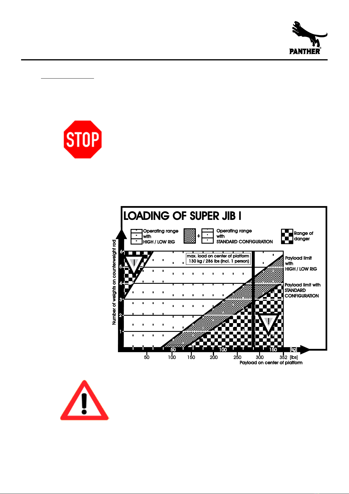
• The loading diagram must be observed.
• In any case, before commissioning of SUPER JIB I, steadiness must again be tested using
the maximum pitching moment to be expected.
• The horizontal and vertical field of traverse of SUPER JIB I must in any case be kept free.
• Use of the Panther Steer out Extention (Code no. 123915 for Evolution/Classic or Code no.
100507 for Super Panther 3) is recommended
• Do only use Panther original accessories
• Combined seat extensions (vertical/horizontal) with the order numbers 110, 111, 112,
105663, 105662, 105661 must not be used. Use only vertical seat extensions or combined
seat extensions marked with “HD” (=heavy duty).
• take care, that during installation and operation there is an absolutely hard, inflexible
underground, which is absolutely smooth and level. No inclined plane!
• Maximum wind during operation: 40 km/h
• during studio and rail operation, it must be taken care that no hard or loose objects can
be rolled over. Even small spots of unevenness may endanger secure standing and dri‑
ving. Do not use pneumatic wheels!
• Swing out all 4 wheel arms. Make sure that the locking bolts of the wheel arms are lo‑
cked.
• The sequence of installation and loading instructions must be observed in any case.
• SUPER JIB I may only be installed in the variants shown within these operating instruc‑
tions.
• Take care, that the platform height may never exceed 3 m / 9‘10“ from ground (that
means you may never swing out the outrigger e.g. outside a window or over the railing
of a bridge. The underlay of tracks must be choosen that the max. height of the platform
may not exceed 3 m / 9‘10“.

Page ‑ 4
Manual | English
2. Special riscs:
DANGER OF PINCHING !
During Operation In the area of these yellow
signs, no persons and / or body parts (for in‑
tance hands, arms...) may be situated.
ATTENTION !
In no case may persons be below the platform
and the counterweights.
• The safety zone of 0.5 m must be kept in all directions. Please look out for possible pin‑
ching during assembly and operation.
• Switch switch „SUPER JIB“ on the front panel to „ON“. „SPEED“ has to be switched to „1“
or „2“.
• Do not use „SPEED“ in position „3“ or „4“. This could lead to motor damage.
• The horizontal and vertical field of traverse of SUPER JIB must be kept free.
• By turning the Super Jib arm and driving in curves, centrifugal force is created, which may
add up and may impair steadyness.
• For safety reasons, it must absolutely be observed that the dolly stands/drives on abso‑
lutely level and stable, inflexible ground. During driving, absolutely look out that no hard
or loose object can get beneath the wheels and impair toppling safety. Example: Cable
within the studio, etc. This also applies to operation on rails.
• Safety regulations prescribe buckling of the safety belt for the operator. The manufactur‑
er for this purpose offers bucket seats with safety belt.
• All loads projecting beyond the platform change the load diagram and endanger steadi‑
ness This for instance also concerns bending outside of the camera man.
• When pivoting Jibarm, then observe that possibly occurring forces may impair steadiness
(depending on acceleration).
• To prevent possible collision with the steering wheel, use the steering steer out extensi‑
on.
• Do not leave loose objects lying on the platform.
• During disassembly in reverse order, observe load diagram.

Page ‑ 5
Manual | English
3. Check-List for assemby
Please check which konfiguration is best for your shooting.
The following criteria have to be considered:
• height • limits in weight
• working distance • payload required
• spatial limits • access to shooting place
Take your time to securely assemble, to check and to test the system before use.
1. Transport Do not expose the outriggers and rods to heavy strokes, do
not bend ropes.
2. Auxiliaries Water level
Support device (e.g. small ladder, tripod, etc.)
3. Ground No slope: check with water level
Use sub‑base in case of a slope
If the ground can only be loaded up to 1500 kg/ m² the load
has to be distributed by a reasonable sub‑base.
4. Basis No slope: check with water level
Min. 1500 kg/ m² load capacity of sub‑base
5. Assembly Check whether all necessary parts are available
Assemble according to instruction
Observe safety instructions
CAUTION !
Outtrigger have to be supported under the load center of gravity if the out‑
rigger is loaded in only one direction. It is obligatory to observe the safety
instructions of the operating manual.

Page ‑ 6
Manual | English
4. Information on load (payload)
iMPORTANT !
The SUPER JIB load (payload) comprises the sum of weights of all ele‑
ments on the jib’s platform (camera operator, remote head, camera,
seat extension etc.).
Plattform Plattform
unloaded loaded
ATTENTION !
Change of load on one side of any already balanced jib arm will cause
an abrupt imbalance which can result in the dolly overturning. The
camera operator should only get on or off the jib after receiving ap‑
provalby the jib operator. Also, the camera
• The SUPER JIB I may only be assembled according to the assembly options shown in this
operating manual. Assembly variations not shown in the manual are not allowed!
• When panning or turning the outrigger, and when driving curves, centrifugal forces are‑
generated which can add up and may possibly affect stability.
• Check the SUPER JIB I daily with regard to functioning, damage, and missing parts.
Damaged and/or missing components must be replaced immediately before further use
of the equipment.
• Mark the SUPER JIB I area of operation (driving/panning area) with flags, signs or similar
items. Keep away any people from the operating area, to avoid anyone being hit by out
rigger and/or dolly.
• Do not let the outrigger bang down at the end of the operating range.
• Check the SUPER JIB I operating area thoroughly for any possible risks or danger. Always
conduct test runs before filming.
• Interrupt use of the SUPER JIB I if a component is damaged or not assembled correctly.

Page ‑ 7
Manual | English
5. Loading
The following load diagram shows the number of nessessary counterweights (Panther
counterweights 15 kg, code no. 104378) dependent upon a centric load of platform.
IMPORTANT !
The Load diagram shows figures for centrical load of the platform in
starting position of the column. These figures are impaired by:
• fast acceleration and braking.
• uneven standing/driving area.
• superstructural parts and accessories and by dislocation of weight
by the persons outside of the platform.
ATTENTION !
It is necessary to keep to the line of optimum loading,so that the motor
is not overloaded. If the motor is constantly overloaded, then this may
lead to motor damage.
SUPER JIB I may not be operated manually in connection with dolly (not
without connecting rod. This could lead to motor damage.

Page ‑ 8
Manual | English
6. Components
The SUPER JIB I is conceptualized for individualized build respective to use and requirement.
In the following list, all components comprising the SUPER JIB I system (code no. 100504) are
listed.
For following orders, the single components are shown with their code numbers.
illustration not to scale
Darstellung nicht maßstabsgetreu
product name
Bezeichnung
code no.
Art.-Nr.
Super Jib I
Super Jib I
100504
Qty.
Anzahl
consisting of
bestehend aus
code no.
Art.-Nr.
1 Super Jib Arm I
Super Jib Arm I
108766
1 Super Jib II ring
Super Jib II Ring
108218
1 Counterweightrod for Vario Jib, SJ I
(6 weights)
Gewichtsstange für Vario Jib, SJ I
(6 Gewichte)
114094
1 Platform for Super Jib I
Plattform für Supert Jib I
112753
1 connecting rod SJ I
Verbindungsstange SJ I
112722
illustration not to scale
Darstellung nicht maßstabsgetreu
product name
Bezeichnung
code no.
Art.-Nr.
High Low Rig I
Hoch Tief Ausleger I
100506
6.1 Optionales Accessories

Page ‑ 9
Manual | English
7. Setup instructions
7.1 Preparation
a) Ground
The ground must be firm and level. If there is an incline, specialized substructures or tracks
with an adequate foundation must be used.
ATTENTION!
The ground’s minimum loading capacity must be 1500 kg / m².
b) Foundation
The foundation must be built carefully and without slope. It is especially important to take
care that supporting materials (e. g. wedges) cannot be dislodged or be moved inadvertently.
ATTENTION!
The foundation’s minimum loading capacity must be 1500 kg / m².
c) Track operation
Please heed the information in the operating manual respective to the track system used.
Use only original Panther track systems.
During the track build, the dolly brakes must be activated. Should the dolly have no brakes,
it should be blocked in place with clamps set on the tracks, in order to avert uncontrolled or
runaway rolling.
ATTENTION!
During track operation, the tracks must be level. No slopes allowed!

Page ‑ 10
Manual | English
Step 1 – Swinging out the wheel arms
• All four wheel arms swung out and locked into
place.
ATTENTION!
The wheel arm is only locked
when the blue plunger has visibly
and audibly snapped into the
appropriate hole.
INFORMATION !
The SUPER JIB I can be used with
Super Panther 3, Classic or Evolu‑
tion Dollies.
_
_
Step 2 – Switch electronics
• Switch dolly to SUPER JIB operating mode.
For Classic Dolly / Super Panther Dolly:
Switch “SUPER JIB” switch to “ON” position.
For Evolution Dolly:
Press “SUPER JIB” button.
7.2 Assembly

Page ‑ 11
Manual | English
Step 3 – Remove seat arms from seat turret.
• Remove stop screw from bottom of threaded
shaft u.
• Loosen seat arm by lifting it and sliding it off
shaftv.
• Do not reattach the stop screw, as it can collide
with the SUPER JIB ring
w.
ATTENTION !
Do not reattach the stop screw! u
‑ Danger of collision!
PINCH POINT WARNING !
There is very little space between
the seat arm shaft and the inside
of the SUPER JIB ring!
w
.
u
_
v
w
_
_
Step 4 – Build Ring
• Put the SUPER JIB ring on the dolly.
• Lock down ring with all four screws.
necessary parts
1x Super Jib II Ring 108218

Page ‑ 12
Manual | English
Step 5 – Build SUPER JIB I
• Mount the SUPER JIB I to the Euro mount on the
dolly column. The dolly seat turret should be
positioned perpendicular to the jib arm.
• Screw the SUPER JIB’s knurled screw tightly ino
the Euro mount u.
• After screwing the knurled screw tight, lock it
into place using the screw lock lever v.
u
v
necessary parts
1x Super Jib Arm kpl. 108766
Step 6 – Build connecting rod
• Attach connecting rod to the appropriate point on
the jib arm.
• Test locking screw to make sure it is tight.
necessary parts
1x connecting rod

Page ‑ 13
Manual | English
Step 7 – Fold out arm rear
• Open the snap‑lock.
• Fold out the arm segment towards the rear.
PINCH POINT WARNING !
There is a pinch point at the
folding junction of the arm
segments!
_
_
Step 8 – Attach connection rod to ring
• Hang the lower profile wheel of the connection
rod into the SUPER JIB ring.
• Set the upper profile wheel into place. Make
sure that the upper wheel shaft locks into the
corresponding relief in the
ATTENTION !
The profiles of the two wheels
must tightly surround the profile
of the SUPER JIB ring.
INFORMATION !
It is possible that the column must
be vertically repositioned before
the connection rod can be moun‑
ted.
_

Page ‑ 14
Manual | English
Step 9 a – Build Platform
• Hang the platform onto the appropriate locating
pin and lock it into place with the knurled screw.
• After screwing the knurled screw tight, lock it
into place using the screw lock lever.
• Proceed to step 10.
necessary parts
1x Super Jin I Plattform 112753
Step 9 b - ALTERNATIVE, build optional High/Low Rig
• Hang the optional High/Low Rig onto the approp‑
riate locating pin and lock it into place with the
knurled screw.
• After screwing the knurled screw tight, lock it
into place using the screw lock lever.
INFORMATION !
The High/Low Rig can be used in
two positions. As such it must
be oriented up or down and the
knurled screw set in the appropri‑
ate position.
necessary parts
1x High Low Rig I 100506
• Hang the platform onto the appropriate locating
pin and lock it into place with the knurled screw.
• After screwing the knurled screw tight, lock it
into place using the screw lock lever.
necessary parts
1x Super Jin I Plattform 112753

Page ‑ 15
Manual | English
Step 10 – Build counterweight rod
• Push the counterweight rod through the hole in
the rear arm segment and lock with the screw.
necessary parts
1x Counterweightrod for Vario Jib, SJ I
(6 weights)
114094
Step 11 – Build counterweights
• Mount weights as appropriate for the front load.
(1 counterweight = 15 kg / 33 lb).
• Secure counterweights against accidental slippa
ge with the security ring‑splints.
ATTENTION !
When loading the platform or
counterweight rod, always pay
attention to the loading table in
section 5!
necessary parts
6x Counter weight, 15 kg / 33 lb 104378

Page ‑ 16
Manual | English
8. Start of operation
IMPORTANT !
Before loading (remote head mount, counterweight rod) or using the jib, all
fastening elements (screws, hooks etc.) must again be checked that they are
correctly secured.
IMPORTANT !
The SUPER JIB I must be balanced at all times. For this purpose, observe the
information on the load diagram and section 5.
IMPORTANT !
Observe the special safety instructions in section 2.
Max. load: 130 kg / 286 lb
Max. wind speed: 40 km/h
Max. travel speed: 0,2 m/sec / 8“/sec
Max. operating weight: 500 kg / 1102 lb
Min. ground loading capacity: 1500 kg/m² / 33 07 lb/1550 sq inch

Page ‑ 17
Manual | English
9. Technical specifications
weight 1: 52 kg / 115 lb
Max. Payload (Center of
platform):
130 kg / 287 lb
range of elevator: ca. 135 cm / approx. 4‘5“
without High Low Rig with High Low Rig 2
platform
top pos.
platform
lower pos.
platform
top pos.
platform
lower pos.
max. hight of platform: 200 cm / 6‘7“ 177 cm / 5‘10“ 235 cm / 7‘9“ 148 cm /4‘10“
min. hight of platform: 65 cm / 2‘2“ 42 cm / 17“ 100 cm / 3‘3“ 13 cm / 5“
lenght of front Jibarm 3: 126 cm / 4‘2“
lenght of front Jibarm 4: 121 cm / 2‘12“
max. counterbalance: 90 kg ( 6 x 15 kg) / 198 lb (6 x 33 )
Dolly compatibility: Super Panther, Panther Classic, Panther Evolution
Jib mount required: Euro Mount
Camera head mount: Euro Mount
1without High Low Rig
2accessorie (code no. 100506)
3between center of rotation and front side of platform (without High Low Rig)
4between center of rotation and back side of jib arm

Page ‑ 18
Manual | English
10. Service and Maintenance
The SUPER JIB I is a very solid piece of equipment that guarantees reliable work without a lot of
maintenance work.
To guarantee a long life and stable quality, it is advisable to treat all elements of the crane very
carefully.
INFO !
For damages occurred due to inappropriate treatment we do not accept any
warranty claims.
After working with the crane, particularly after working in a dirty, dusty, sandy, wet
and salty surrounding, the crane has to be cleaned and maintained very carefully.
Please keep the suspension cables in good condition.
ATTENTION !
Interrupt the work with the crane immediately, if only a small part of the crane
is damaged or missing.
Maintenance and repair should only be made by trained and competent persons. Panther GmbH
offers service seminars, which will be hold according to your desires. For exact dates, please call
+49 (89) 613 900 30 (Panther‑Service).
According to ZH 1/222 / 3.2 and UVV BGV C1 (former VBG 70), the safety and machine appli‑
ances have to undergo an interim check up by a competent person at least every 4 years and at
least every year by an expert (repeated check up ‑ see maintenance book).
Please check all cables and turning buckles for damages (e.g.bend cables). If necessary, parts of
the crane have to be exchanged.

Page ‑ 19
Manual | English
11. Warranty
We warrant that the products are free of manufacturing defects in material. Both for mechanical
and for electronic parts, the warranty period is 12 months. The warranty
period begins with the date of delivery.
Any warranty shall, however, expire if our operating and maintenance instructions are not com‑
plied with, if changes are made to the products, or if parts of our equipment
are replaced with parts that do not correspond to the original specifications; the same shall
apply to improper handling of the equipment.
The purchaser undertakes to exempt us from any claims for compensation which might arise on
the part of third parties vis‑à‑vis us, whether resulting from putting into service or from using
the equipment.
The purchaser must inform our costumer service management in writing about any discernible
defects without delay – at the latest, however, within one week after receipt of the delivered
item. Defects which do not become discernible within this period, even after careful examina‑
tions, must be reported to us by the purchaser in writing immediately after discovery.
In the event that the purchaser should report that the products do not correspond to the warran‑
ty, we may require at our discretion that either
a) the defective equipment or the defective part is to be sent to us for repair and subse‑
quent return, or
b) the purchaser keeps the defective equipment or the defective part available, and we shall
commission an expert who will be sent to carry out the repair.
Transport cost and travelling expenses incurred for the purpose of remedying defects shall be
borne by the purchaser.
Defects which occur to the equipment as a result of natural wear and tear shall not be covered
by the warranty. When asserting claims under warranty, it is the duty of the purchaser to prove
that the defects were not caused by circumstances which are among the risks within his sphere
of responsibility (such as transport damage, improper operation, etc.).
Any further claims in particular claims for damages for direct or indirect damage are excluded.
If after an appropriate time it is not possible to remedy the defect, the purchaser may at his dis‑
cretion demand a reduction of the payment or cancellation of the contract.
Only the direct purchaser shall be entitled to make warrantly claims against us; such claims are
not assignable.
Oberhaching, April 2006

Page ‑ 20
Manual | English
12. Inspection Book
Product: Panther SUPER JIB I
Manufacturer: Panther GmbH
Raiffeisenallee 3
82041 Oberhaching
Payload: 130 kg / 286 lb
Year of construction:
Serial no.:
User: company:
address:
city:
country:
12.1 EU - Declaration of Conformity
The product has been developed, designed and manufactured
in conformity with the following regulations:
EC regulations: Maschinenrichtlinie 98/37 Anh. I/IV
harmonized technical
regulations:
Sicherheit von Maschinen EN 292 /394
National regulations Veranstaltungs‑und Produktions‑
stätten für szenische Darstellung
BGI 814
The technical documentation is complete.
The Operating Instructions for the machine have been submitted.
Oberhaching. 30‘th of June 2006
_
_________________________
Erich Fitz, President
We have fulfilled the essential safety and health requirements.
In case of technical alteration of the machine by a third party, this declaration loses its validity.
Table of contents
Other Panther Professional Video Accessories manuals