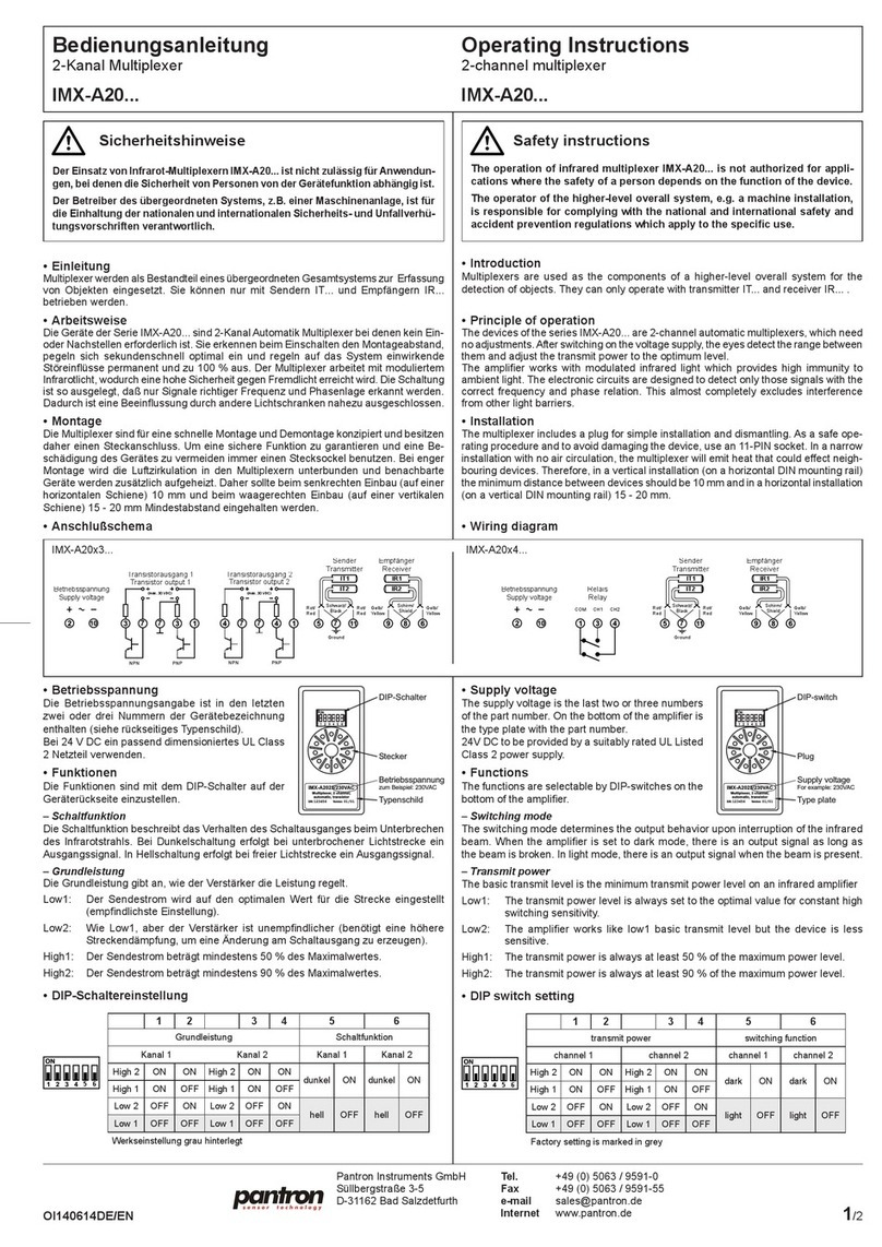
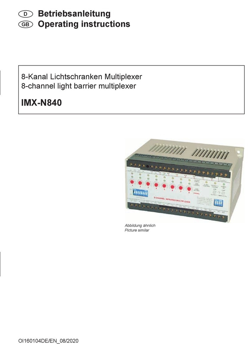
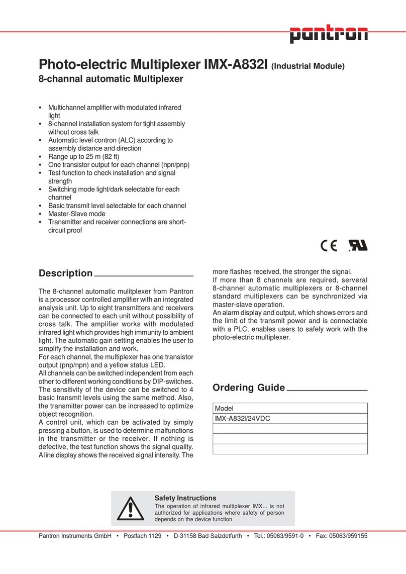
Pantron IMX-A832I User manual

Pantron Automation, Inc. • P.O. Box 6039 • Gastonia, NC 28056 • Phone: 800-211-9468 • Fax: 704-864-0120
Photo-electric Multiplexer IMX-A832I (Industrial Module)
8-channel automatic Multiplexer
Multichannel amplifier with modulated infrared
light
8-channel installation system for tight assembly
without cross-talk
•Automatic level control (ALC) according to
assembly distance and direction
Range up to 25 m (82 ft)
One transistor output for each channel (npn/pnp)
Test function to check installation and signal
strength
Switching mode light/dark selectable for each
channel
Basic transmit level selectable for each channel
Master-Slave mode
Transmitter and receiver connections are short-
circuit proof
Description
The 8-channel automatic multiplexer from Pantron
is a processor controlled amplifier with an integrated
analysis unit. Up to eight transmitters and receivers
can be connected to each unit without possibility of
cross talk. The amplifier works with modulated
infrared light which provides high immunity to ambient
light. The automatic gain setting enables the user to
simplify the installation and work.
For each channel, the multiplexer has one transistor
output (pnp/npn) and a yellow status LED.
All channels can be switched independent from each
other to different working conditions by DIP-switches.
The sensitivity of the device can be switched to 4
basic transmit levels using the same method. Also,
the transmitter power can be increased to optimize
object recognition.
A control unit, which can be activated by simply
pressing a button, is used to determine malfunctions
in the transmitter or the receiver. If nothing is
defective, the test function shows the signal quality.
Aline display shows the received signal intensity.The
ledoM
CDV42/I238A-XMI
Safety Instructions
The operation of infrared multiplexer IMX... is not
authorized for applications where safety of person
depends on the device function.
more flashes received, the stronger the signal.
If more than 8 channels are required, several 8-
channel automatic multiplexers or 8-channel standard
multiplexers can be synchronized via master-slave
operation.
An alarm display and output, which shows errors and
the limit of the transmit power and is connectable
with a PLC, enables users to safely work with the
photo-electric multiplexer.
Ordering Guide

IMX-A832I
2July 2001, subject to change
Technical Data
Operating basis thgil-RIdetaludoM egatlovylppuS CDV42
)maebhguorht(range.xam ecnarelotegatloV %01
01P-RI,01P-TIsrosneS m51 noitpmusnocrewoP W01
01P-RI,PH01P-TIsrosneS m02
ycneuqerftimsnarT zHk0,4
yalpsidsutatstuptuO nürgDELx8 rewoptimsnarT citamotuA
:yalpsidnoitcnufitluM leveltimsnartcisaB 2hgiH/1hgiH/2woL/1woL
noitcnufcitamotuA neergDELx8 deepsxelpitluM )zH03(sm43
mralA derDELx8
leveltimsnartcisaB wolleyDELx8 :tuptuorotsisnarT pnp/npn
:yalpsidedomnoitarepO ).xam(atadgnihctiwS CDV03...21/Am001
edomlamroN neergDEL TemitnoitcaeR
NO
T/
FFO
sm33/sm33
edomtseT wolleyDEL ycneuqerfgnihctiwS zH51
yalpsidedomevalS wolleyDEL
tuptuomralA pnp
noitcnufgnihctiwS elbatceles,krad/thgil atadgnihctiwS Am001.xam/CDV42
noitcnufevalS sey
yaledCLA s2 noitcennoC 80,5MRsredaehpirtS
noitatneirognitnuoM eerf
gnisuoH cisalP gnitnuoM gnitnuomliarNID
)noitarepo(erutarepmeT C°06+...C°52-
)egarots(erutarepmeT C°06+...C°04- )mm(eziS 7,24Hx4,521Bx712L
Dimensions
dimensions in millimeters
217
125,4
5,08
CAN Schnittstelle
- optional -
42,7

IMX-A832I
July 2001, subject to change 3
Wiring diagram
C AU TI O N !
The AC-supply devices are isolated from main. A grounded connection on the low voltage side is required. In
synchronized operation of multiple devices (master/slave), we recommend installation using short connecting
cables.
Transistor output:
NPN PNP
yellow
black
OutputReceiver Transmitter
24VDC
1
2
3
4
5
6
8
7
IR-TransmitterIR-Receiver
black black black black black black black
Voltage
Supply
Ground
Transistor
output
12345678
Master OUT
from master
Slave IN
following
slave devices
Alarm
output
PNP
yellow yellow red red red redyellow
OutputTransmitter
24VDC
R
L
external
power
supply
12 VDC - 30 VDC
OutputTransmitter
24VDC
R
L

IMX-A832I
4July 2001, subject to change
revieceR)wolley(sulP
3
)dleihs(dnuorG
3
11.oN3.oN
22.oN3.oN
34.oN6.oN
45.oN6.oN
57.oN9.oN
68.oN9.oN
701.oN21.oN
811.oN21.oN
General Description
1. Principle of operation
The system (consisting of transmitter, receiver and
one multiplexer) works with modulated infrared light.
The device activates the sensor heads cycling one
after the other (multiplex operation). During the
activation, the state of each channel is evaluated.
According to the channels condition, the appropriate
transmit power is calculated (Automatic Level
Control) and the display and outputs are set.
2. Automatic level control
Automatic Level Control is the main feature of
Pantrons infrared automatic multiplexer.The
transmitter power level is continuously calculated to
an optimal value to guarantee steady switching
reaction, independent from distance between
transmitter and receiver, mounting position,
temperature etc.
3. Connections
Wires are connected with one row of 38 terminals
(see picture 1). Phoenix contact.
Signal strength
no Transmitter detected
no Receiver detected
Low 1
Low 2
High 1
High 2
Automatic-Function
Alarm
OutputReceiver Transmitter
24VDC
Normal Operation Mode Test Operation Mode
1-8 green
1 red
2 red
1 yellow
2 yellow
3 yellow
4 yellow
1-8 green
1-8 red
STATUSSTATUS MEANING MEANING
8-CHANNEL INFRARED
AUTOMATIC-MULTIPLEXER
123456789111213
14
15
16
17
1819
2021
22
23
24 25
26
27
28
29
3031
3233
34
35
3637
38
picture 1: Numbers of terminals
a) Voltage Supply (V. SUPPLY)1
Before connecting the multiplexer, look on the side
and check if the power supply is the same as the
connection value. The power supply will be connected
on terminal number 37 (positive) and terminal
number 38 (neutral).
lennahCtuptuorotsisnarT
152.oN
262.oN
372.oN
482.oN
592.oN
603.oN
713.oN
823.oN
rettimsnarT)der(sulP
2
)kcalb(dnuorG
2
131.oN51.oN
241.oN51.oN
361.oN81.oN
471.oN81.oN
591.oN12.oN
602.oN12.oN
722.oN42.oN
832.oN42.oN
b) Transmitter (IT...)1
Eight infrared transmitters can be connected to one
8-channel multiplexer. Connect the transmitter as
shown in table 1.
Table 1: Transmitter terminals
c) Receiver (IR...)1
Eight infrared receivers can be connected to one
8-channel multiplexer. Connect the receivers as
shown in table 2.
Table 2: Receiver terminals
d) Transistor output
For each channel, the multiplexer has one transistor
output (wiring table 3) which can be used as a pnp or
npn outputdepending on the connection. All outputs
have a common ground terminal (terminal no. 34).
The maximum allowable switching current is 100 mA
at 12 V DC to 30 V DC.
Table 3: Transistor output terminals

IMX-A832I
July 2001, subject to change5
e) Alarm output (ALARM)1
The alarm output has +24 V DC output voltage by
alarm. The maximum load
from the output is 100 mA.
Connect the evaluation unit
between positive (terminal
number 33) and neutral
(terminal number 34), see
picture 2.
Picture 2: Alarm output
f) Master OUT
To synchronize more than one 8-channel multiplexer,
the MASTER OUT output (connection terminal
number 35, see picture 1) gives a signal to the
following device.
Note:Do not connect the MASTER OUT terminal
with the MASTER OUT terminal of the next
device
g) Slave IN
To synchronize more than one 8-channel multiplexer,
the SLAVE IN input (connection terminal number 36,
see picture 1) receives the signal from the previous
device.
Note:The SLAVE IN terminal should be wired to a
MASTER OUT terminal.
4. Master-Slave operation
The master-slave operation allows synchronized
action of multiple 8 channel devices, including all
Pantron manual and automatic series. Therefore, the
same channel number is active on each device in
the chain at the certain time (see picture 4). With a
suitable arrangement of sensor pairs, the mutual
influence between the amplifiers can be prevented.
Picture 3: Master-Slave operation
Note:Do not wire the MASTER OUT terminal from
the last device with the SLAVE IN terminal from
the first device.
5. Operation mode terminology
The device has 2 different operation modes:
a) Normal mode
This is the standard mode that is implemented after
switching the supply voltage on, as well as after the
RESET push-button has been pressed.
b) Test mode
This mode is used for the physical alignment of
the sensor heads and to test the set up and wiring.
The multiplexer displays the following information:
Signal strength
Sensor error
selected basic transmit level
The sensor heads are activated cycling one after the
other.The state of each channel will not be shown
and the outputsmaintain the state they are in.
6. Functions terminology
The functions of the amplifier can be switched to
different working conditions. The functions are
selectable by DIP-switches behind the front panel.
a) Switching mode1
The switching mode describes the output behavior
on interruption of the infrared beam. There are some
differences in the light circuit (light)1and the dark circuit (dark)1.
Light mode operation: The output switches to ground
(terminal number 34).
Dark mode operation: The output switches to the
+24 V DC.
b) Basic transmit level (transmit power)1
The basic transmit level is the minimum transmit
power level of an infrared transmitter.
Low 1: This is the standard operating mode of the
automatic level control (ALC). The trans-
mit power level is always set to the optimal
value for constant high switching sensitivity.
Low 2: The multiplexer works like the Low 1 basic
transmit level but the device is less sensi-
tive.
High 1: The transmit power level is always at least
50 % of the maximum power level.
High 2: The transmit power level is always at least
90 % of the maximum power level.

IMX-A832I
6July 2001, subject to change
1. Choose the sensor heads
Before you turn on the multiplexer, select the transmitter and receiver for your application. Each channel needs
one transmitter and one receiver. This includes choosing the sensor heads body style and cable length or quick
disconnect that meets your requirements.
2. Installation of the multiplexer
The multiplexer can be installed with two holes (DIN 46121) or a DIN rail mounting clip (DIN 46277). The wiring
diagram is printed on the front label of the multiplexer or see Wiring diagram. For more information see
General Description, point 3 Connections.
3. Choose the function
Operating Instructions
Display contents:
H1 - H8: Output status indicator (yellow)
H9: Slave mode indicator (yellow)
H10 - H17: Multi function display (green/yellow/red)
H18: Operation mode display (green/yellow)
S1: Test button
S2: Reset button
DIP1: DIP-switch switching mode
DIP 2 - DIP 3:DIP-switch basic transmit level
Signal strength
no Transmitter detected
no Receiver detected
Low 1
Low 2
High 1
High 2
Automatic-Function
Alarm
OutputReceiver Transmitter
24VDC
Normal Operation Mode Test Operation Mode
1-8 green
1 red
2 red
1 yellow
2 yellow
3 yellow
4 yellow
1-8 green
1-8 red
STATUSSTATUS MEANING MEANING
8-CHANNEL INFRARED
AUTOMATIC-MULTIPLEXER
H1
H10
H2
H11
H3
H12
H4
H13
H5
H14
H6
H15
H7
H16
H8
H17
H9
H18
S1
S2
DIP 1
DIP 2
DIP 3
1hctiwS-PID 2hctiwS-PID 3hctiwS-PID
edomgnihctiws
1
rewoptimsnart
leveltimsnartcisab
1
level
1
FFOthgil
1
FFOwoLFFO1
NOkrad
1
NOhgiHNO2
The function are selectable by three DIP-switches located behind the
front panel of the photo-electric multiplexer (see picture 5). Take off the
front panel to change the settings.
For complete description of function, see General Descriptionpoint 5
Functions Terminology.
The allocation of the function of the DIP-switches is described in table 4.
All channels can be switched independent from each other to different
functions. The number of the DIP-switch is equal with the number of
the transmit channel.
Picture 5: DIP-switches
Table 4: Functions
The DIP-switch settings will take effect immediately after switching on the power supply. DIP-switch
settings should not be changed during operation of the multiplexer.
DIP-Switch 1
DIP-Switch 2
DIP-Switch 3

IMX-A832I
July 2001, subject to change7
IMX-A832I/24VDC
IR-Multiplexer
8-Channel - Automatic
V00/0047/000001
Pantron Instruments GmbH - Germany
4. Check the supply voltage
On the right side of the multiplexer is the type plate. The supply voltage is the last two or three numbers of the
part number. Check if this value is the same as the connection value.
5. Operating procedure
Switch the power supply on. The operation mode display H18 (OPERATION MODE)1lights green. The device
is in the normal operation mode. From the normal operation mode, press S1 to enter the test mode. Pressing
S2 will cause a reset equivalent to the power-on-reset.
Note:If the multi function display from one channel lights red (ALARM)1after switching on the power supply,
the contact between transmitter and receiver from this channel is interrupted (polluted or misaligned) or
the distance between the sensor heads is too far.
a) Normal mode
The operation mode display H18 lights green.
The sensor heads will be activated cycling one after the other. The information (interrupt or clearence, transmit
power etc.) are evaluated and the state of the displays and transistor outputs are continuously shown. The
displays H1 to H8 (OUTPUT-STATUS)1indicate the state of the outputs. H10 to H17 (AUTOMATIC-FUNCTION)1
indicate the state of the Automatic Level Control. If the beam is made between the transmitter and receiver of
one channel the AUTOMATIC-FUNCTION1LED from this channel lights green. The ALC is active and the
transmit power will be turned automatically on an optimum level. If the infrared beam is interrupted, the multi
function display is off and the transmit power level will be constant until the infrared beam is clear again. For
description of how the device work, see table 5.
Table 5: Switching logic
After the sensor heads become polluted, the amplifier will raise the transmit power level.At 95 % of the maximum
transmit power, the multi function display lights red (ALARM)1and the alarm output is active.
sutatsmaeB gnihctiwS
noitcnuf
sutatstuptuO
rotacidni
rotsisnarT
tuptuo
thgilCDV42
kradV0
kradV0
thgilCDV42
supplyc voltage
for example: 24 V DC

IMX-A832I
8July 2001, subject to change
b) Test mode
The operation mode display H18 lights yellow.
This operation mode is used for the physical alignment of the sensor heads and to test the installation (wiring
and setting). The sensor heads will be activated cycling one after the other.The state of the beam is not
displayed. The transistor outputs maintain the state they are in. After
entering the test mode only one LED from the display H1 to H8
lights and indicates the channel, which refers to the LEDs from the
multi function display H10 to H17 (H1 lights yellow = Infromation for
channel 1). The multi function display shows the beam status (see
below). After pressing S1 (TEST)1again the multi function display
indicates the setting (see below). Pressing S1 (TEST) again the
display indicates the information from channel 2. If the information
from the last channel is diplayed and after pressing S1 again the
device indicates the information from channel 1 (see picture 6).
Picture 6: Over view test mode
Pressing S2 (RESET)1or after a few seconds without pressing the buttons, the device goes back to the normal
operation mode
·Beam status
The display H10 to H17 indicates information about the beam quality, resp. errors at the sensor heads. If
nothing is defective, H10 to H17 indicates the signal strength of the selected channel. The more green LEDs
are visible, the better the received signal is. Use this option for the mechanical alignment of your photo-eyes.
One or two red LEDs indicate errors in the sensor wiring:
- H10 lights red - Error at the transmitter terminal
The transmitter has a short circuit, the cable is broken or no transmitter is connected.
- H11 lights red - Error at the receiver terminal
The receiver has a short circuit, the cable is broken or no receiver is connected.
·Parameter settings
The multi function display H10 to H13 shows information about the adjusted basic transmit level. The following
indicators are possible:
H10 lights yellow - Low 1
H11 lights yellow - Low 2
H12 lights yellow - High 1
H13 lights yellow - High 2
Test mode
Beam status
Normal operating
mode
S1
S1
S1
next channel
Test mode
Settings
S2S2
1Inscription front lable
2Core coding transmitter cable
3Core coding receiver cable
Table of contents
Other Pantron Multiplexer manuals
Popular Multiplexer manuals by other brands

Patton electronics
Patton electronics Multiport Asynchronous Statistical Multiplexer... Getting started guide

GE Interlogix
GE Interlogix S734DV instruction manual

FOR-A
FOR-A USF-1013MUX Operator's manual

Raisecom
Raisecom RC3000 user manual

Gopel Electronic
Gopel Electronic USB 4112 user manual

Irenis
Irenis BLANKOM BMM-1716 user manual