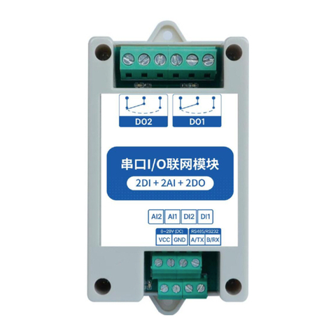
Ebyte ME31-AAAX2240 User manual

Chengdu Ebyte Electronic Technology Co.,Ltd. ME31-AAAX2240_UserManul_EN
Copyright ©2012–2022,Chengdu Ebyte Electronic Technology Co.,Ltd I
ME31-AAAX2240
I/O networking module

Chengdu Ebyte Electronic Technology Co.,Ltd. ME31-AAAX2240_UserManul_EN
Copyright ©2012–2022,Chengdu Ebyte Electronic Technology Co.,Ltd I
Contents
Chapter 1 Product overview ...........................................................................................................................................2
1.1 Introduction ...................................................................................................................................................... 2
1.2 Features ............................................................................................................................................................ 2
1.3 Application typology diagram ..........................................................................................................................3
Chapter 2 Quick start ......................................................................................................................................................4
2.1 Devices required ...............................................................................................................................................4
2.2 Device connection ............................................................................................................................................ 5
2.2.1 RS485 connection ................................................................................................................................. 5
2.2.2 AI analog input connection ................................................................................................................... 5
2.2.3 DI switch input connection ................................................................................................................... 6
2.2.4 Relay output connection ........................................................................................................................6
2.2.5 Simple use ............................................................................................................................................. 6
2.3 Parameter configuration ...................................................................................................................................7
2.4 Control test ....................................................................................................................................................... 8
2.4.1 Modbus TCP control ............................................................................................................................. 8
2.4.2 Modbus RTU control ............................................................................................................................ 9
Chapter 3 Technical indicator ...................................................................................................................................... 10
3.1 Specification and parameter ...........................................................................................................................10
3.2 Device default parameter ............................................................................................................................... 11
3.3 Dimensions .....................................................................................................................................................12
3.4 Ports and indicators ........................................................................................................................................ 13
Chapter 4 Product function introduction ......................................................................................................................15
4.1 DO output .......................................................................................................................................................15
4.1.1 Level output ........................................................................................................................................ 15
4.1.2 Pulse output .........................................................................................................................................15
4.1.3 Follow mode ........................................................................................................................................15
4.1.4 Power on state ..................................................................................................................................... 15
4.2 DI input ...........................................................................................................................................................15
4.2.1 Switch input DI acquisition ................................................................................................................ 15
4.2.2 Input filtering ...................................................................................................................................... 16
4.2.3 Input count.......................................................................................................................................... 16
4.3 Active upload ..................................................................................................................................................16
4.4 AI input ...........................................................................................................................................................16
4.4.1 Analog range ....................................................................................................................................... 16
4.4.2 AI original value and engineering value of analog input ................................................................... 17
4.4.3 Input filter parameters .........................................................................................................................17
4.4.4 Input calibration .................................................................................................................................. 18
4.5 Modbus gateway ............................................................................................................................................ 18
4.6 Active upload ..................................................................................................................................................18

4.7 Custom Module Information ..........................................................................................................................18
4.7.1 Modbus address ...................................................................................................................................18
4.7.2 Module name .......................................................................................................................................18

Chengdu Ebyte Electronic Technology Co.,Ltd. ME31-AAAX2240_UserManul_EN
Copyright ©2012–2022,Chengdu Ebyte Electronic Technology Co.,Ltd II
4.7.3 Network parameter ..............................................................................................................................18
4.7.4 UART parameter ................................................................................................................................. 19
4.8 LCD display and parameter configuration .....................................................................................................20
4.8.1 Information display interface ..............................................................................................................20
4.8.2 Device parameter display interface .....................................................................................................20
4.8.3 Parameter configuration ......................................................................................................................20
4.9 Modbus TCP protocol data frame description ............................................................................................... 21
4.10 Modbus RTU protocol data frame description ............................................................................................ 22
4.11 MODBUS parameter configuration ............................................................................................................. 22
4.11.1 DO register list .................................................................................................................................. 22
4.11.2 DI register list ....................................................................................................................................23
4.11.3 AI register list .................................................................................................................................... 23
4.11.4 Module related register ..................................................................................................................... 24
4.11.5 Network related register ....................................................................................................................24
4.11.6 Modbus command operation .............................................................................................................25
Chapter 5 Host computer ............................................................................................................................................. 28
5.1 Acquisition and control .................................................................................................................................. 28
5.2 Parameter setting ............................................................................................................................................29
Revision history ............................................................................................................................................................32
About us ........................................................................................................................................................................32

Chengdu Ebyte Electronic Technology Co.,Ltd. ME31-AAAX2240_UserManul_EN
Copyright ©2012–2022,Chengdu Ebyte Electronic Technology Co.,Ltd 2
Chapter 1 Product overview
1.1 Introduction
ME31-AAAX2240 is equipped with 4 Type A relay outputs and 2
analog (0-20mA/4-20mA) inputs, 2 dry contact input detection, supports
Modbus TCP protocol or Modbus RTU protocol for acquisition and control,
and the equipment is also A network I/O networking module that can be
used as a simple Modbus gateway (automatically send commands with
non-local Modbus addresses through the serial port/network port).
1.2 Features
Good for standard Modbus RTU protocol and MODBUS TCP protocol;
Work with various configuration software/PLC/touch screen;
RS485 acquisition control I/O;
RJ45 acquisition control I/O,support 4 channel master access;
2 channel analog input(0-20mA/4-20mA);
2-channel switch input DI (dry node) ;
4-channel switch output DO (Type A relay) ;
Switch output (DO) supports level mode, pulse mode, follow mode ;
Support custom Modbus address settings;
Support 8 common baud rate configurations ;
DHCP and static IP;
DNS function, domain name analysis;
Support Modbus gateway;

Chengdu Ebyte Electronic Technology Co.,Ltd. ME31-AAAX2240_UserManul_EN
Copyright ©2012–2022,Chengdu Ebyte Electronic Technology Co.,Ltd 3
1.3 Application typology diagram
Modbus TCP application request topology:
Modbus RTU application request topology:

Chengdu Ebyte Electronic Technology Co.,Ltd. ME31-AAAX2240_UserManul_EN
Copyright ©2012–2022,Chengdu Ebyte Electronic Technology Co.,Ltd 4
Chapter 2 Quick start
Note: The test need to carry out with factory parameter.
2.1 Devices required
ME31-AAAX2240
12V SMPS
USB to RS485
Computer
RJ45 Cable
More cables

Chengdu Ebyte Electronic Technology Co.,Ltd. ME31-AAAX2240_UserManul_EN
Copyright ©2012–2022,Chengdu Ebyte Electronic Technology Co.,Ltd 5
2.2 Device connection
2.2.1 RS485 connection
Note: When the 485 bus high frequency signal is transmitted, the signal wavelength is shorter than the transmission
line, and the signal will form a reflected wave at the end of the transmission line, which will interfere with the
original signal. Therefore, a terminal resistance must be added at the end of the transmission line to prevent the
signal from being reflected after reaching the end of the transmission line. The terminal resistance should be the
same as the impedance of the communication cable, with a typical value of 120 ohms. Its function is to match the
bus impedance and improve the anti-interference and reliability of data communication.
2.2.2 AI analog input connection

Chengdu Ebyte Electronic Technology Co.,Ltd. ME31-AAAX2240_UserManul_EN
Copyright ©2012–2022,Chengdu Ebyte Electronic Technology Co.,Ltd 6
2.2.3 DI switch input connection
2.2.4 Relay output connection
2.2.5 Simple use

Chengdu Ebyte Electronic Technology Co.,Ltd. ME31-AAAX2240_UserManul_EN
Copyright ©2012–2022,Chengdu Ebyte Electronic Technology Co.,Ltd 7
Wiring: The computer is connected to the RS485 interface of ME31-AXCX4040 through USB to RS485, A is connected to A, B is connected to B.
Networking: Insert the network cable into the RJ45 port and connect to the PC. Power supply: Use DC-12V switching power supply (DC 8~28V) to
supply power to ME31-AAAX2240.
2.3 Parameter configuration
Step 1: Modify the IP address of the computer to be consistent with the device. Here it is modified to 192.168.3.100
to ensure the same network segment as the device and that the IP is different. Please turn off the firewall and try
again if the step failed;
Step 2: Open the network assistant, select the TCP client, enter the remote host IP192.168.3.7 (default parameters),
enter the port number 502 (default parameters), and select HEX to send.

Chengdu Ebyte Electronic Technology Co.,Ltd. ME31-AAAX2240_UserManul_EN
Copyright ©2012–2022,Chengdu Ebyte Electronic Technology Co.,Ltd 8
2.4 Control test
2.4.1 Modbus TCP control
Use network assistant to control ME31-AAAX2240, first channel DO output.

Chengdu Ebyte Electronic Technology Co.,Ltd. ME31-AAAX2240_UserManul_EN
Copyright ©2012–2022,Chengdu Ebyte Electronic Technology Co.,Ltd 9
To test other function according to below table
Function (function code)
Command
Pull in the first coil (0x05)
01 00 00 00 00 06 01 05 00 00 FF 00
All open(0x0F)
02 00 00 00 00 08 01 0F 00 00 00 04 01 0F
All close(0x0F)
02 00 00 00 00 08 01 0F 00 00 00 04 01 00
Read all DI state(0x02)
01 00 00 00 00 06 01 02 00 00 00 02
Read all DO state(0x01)
01 00 00 00 00 06 01 01 00 00 00 04
2.4.2 Modbus RTU control
Use serial port assistant to control ME31-AAAX2240, first channel DO output.
To test other function according to below table
Function (function code)
Command
Pull in the first coil (0x05)
01 05 00 00 FF 00 8C 3A
All open(0x0F)
01 0F 00 00 00 04 01 0F 74 92
All close(0x0F)
01 0F 00 00 00 04 01 00 3E 96
Read all DI state(0x02)
01 02 00 00 00 02 F9 CB
Read all DO state(0x01)
01 01 00 00 00 04 3D C9

Chengdu Ebyte Electronic Technology Co.,Ltd. ME31-AAAX2240_UserManul_EN
Copyright ©2012–2022,Chengdu Ebyte Electronic Technology Co.,Ltd 10
Chapter 3 Technical indicator
3.1 Specification and parameter
Category
Name
Parameter
Power supply
Operating voltage
DC8~28V
Power indicator
Blue LED indicator
Serial port
Communication
interface
RJ45、RS485
Baud rate
9600bps(can be defined by user)
Communication
protocol
Standard Modbus TCP,Modbus RTU
MODBUS
Device address
Modify via Modbus command and computer
DI input
DI channels
2 channel
Input type
Default dry node
Acquisition
frequency
1 kHz
Input indicator
LED display
AI input
AI channels
2 channel
Acquisition
characteristics
Single-ended input
Input type
0-20mA, 4-20mA
AI resolution
1‰
Acquisition
frequency
10Hz
Input instructions
LED display
DO output
DO channel
4 channel
DO output type
Type A Relay
DO output mode
Level output, pulse output
Relay contact
capacity
30V/7A、250V/7A
Output indication
Red LED
Other
Product weight
150 ±5 g
Working
temperature and
humidity
-40 ~+85℃、5% ~95%RH(no condensation )
Storage temperature
and humidity
-40 ~+105℃、5% ~95%RH(no condensation )
Installation
Din rail installation

Chengdu Ebyte Electronic Technology Co.,Ltd. ME31-AAAX2240_UserManul_EN
Copyright ©2012–2022,Chengdu Ebyte Electronic Technology Co.,Ltd 11
3.2 Device default parameter
Category
Name
Parameter
Ethernet parameter
Working mode
TCP server (Max 4 channel client
access)
Local IP
192.168.3.7
Local port
502
Subnet mask
255.255.255.0
Gateway address
192.168.3.1
DHCP
Off
Local MAC
Depending on chip(fixed)
Target IP
www.ebyte.com
Target port
502
DNS server
8.8.8.8
Active upload
Off
UART parameter
Baud rate
9600bps(8 type)
Check method
None(default)、Odd、Even
Data bit
8
Stop bit
1
MODBUS parameter
Modbus master slave
Slave
Address
1

Chengdu Ebyte Electronic Technology Co.,Ltd. ME31-AAAX2240_UserManul_EN
Copyright ©2012–2022,Chengdu Ebyte Electronic Technology Co.,Ltd 12
3.3 Dimensions

Chengdu Ebyte Electronic Technology Co.,Ltd. ME31-AAAX2240_UserManul_EN
Copyright ©2012–2022,Chengdu Ebyte Electronic Technology Co.,Ltd 13
3.4 Ports and indicators
No.
Sticker
Remarks
1
TX(LED)
UART TX data
2
RX(LED)
UART RX data
3
LINK(LED)
Network link
4
NET(LED)
Network data TX and RX
5
PWR(LED)
Power input
6
DO1(LED)
1st channel relay output
7
DO2(LED)
2nd channel relay output
8
DO3(LED)
3rd channel relay output
9
DO4(LED)
4th channel relay output
10
V-
Negative pole of power input, DC 8V~28V, 5.08mm phoenix terminal.
11
V+
Positive pole of power input, DC 8V~28V, 5.08mm phoenix terminal.
12
NO1
Relay 1 normally open pin, used with the common terminal of relay 1 ,
5.08mm phoenix terminal
13
COM1
Common terminal of relay 1, used in conjunction with the normally open pin of
relay 1 ,5.08mm phoenix terminal
14
NO12
Relay 2 normally open pin, used with the common terminal of relay 2 ,
5.08mm phoenix terminal
15
COM2
Common terminal of relay 2, used in conjunction with the normally open pin of
relay 2 ,5.08mm phoenix terminal
16
NO3
Relay 3 normally open pin, used with the common terminal of relay 3 ,

Chengdu Ebyte Electronic Technology Co.,Ltd. ME31-AAAX2240_UserManul_EN
Copyright ©2012–2022,Chengdu Ebyte Electronic Technology Co.,Ltd 14
5.08mm phoenix terminal
17
COM3
Common terminal of relay 3, used in conjunction with the normally open pin of
relay 3 ,5.08mm phoenix terminal
18
NO4
Relay 4 normally open pin, used with the common terminal of relay 4 ,
5.08mm phoenix terminal
19
COM4
Common terminal of relay 4, used in conjunction with the normally open pin of
relay 4 ,5.08mm phoenix terminal
20
Ethernet
Standard RJ45 interface
21
AI2
Analog input channel 2, support 0 to 20mA current input ,5.08mm phoenix
terminal
22
AI1
Analog input channel 1, support 0 to 20mA current input ,5.08mm phoenix
terminal
23
DI2
Switch input channel 2, support dry contact access ,5.08mm phoenix terminal
24
DI1
Switch input channel 1, support dry contact access ,5.08mm phoenix terminal
25
GND
Ground
26
485-A
A of the RS-485 serial port is connected to the A port of the external device ,
5.08mm phoenix terminal
27
485-B
B of the RS-485 serial port is connected to the B port of the external device ,
5.08mm phoenix terminal

Chengdu Ebyte Electronic Technology Co.,Ltd. ME31-AAAX2240_UserManul_EN
Copyright ©2012–2022,Chengdu Ebyte Electronic Technology Co.,Ltd 15
Chapter 4 Product function introduction
4.1 DO output
The output mode of the relay will output different modes according to the mode set by the user, and the level
output is turned on by default.
4.1.1 Level output
Output according to the level set by the user, the switching characteristics of the level mode are similar to the
function of the self-locking switch.time (unit ms) is main
4.1.2 Pulse output
After the switch output DO is turned on, after the set pulse width time (unit ms) is maintained, the switch
output DO is automatically turned off. Pulse width setting range 50~65535ms (default 50ms).
4.1.3 Follow mode
Change the relay state according to the follower source (DI1, DI2, DI3, DI4) configured by the user, and
multiple outputs can follow the same follower source output. Simply put, the DI detects the input and automatically
outputs the relay with the follower source. When the follow mode is turned on, the follow source should be
configured at the same time, otherwise it will follow the first input by default.off.
4.1.4 Power on state
According to the state set by the user. After the device is powered on, the output relay is turned on according
to the state set by the user, and it is turned off by default.
4.2 DI input
4.2.1 Switch input DI acquisition
Switch input DI measurement level signal or edge pulse signal (rising edge, falling edge). Support dry node
collection, support DI counting function, the maximum count is 65535 (the count is automatically cleared if it
exceeds 65535).
The switch input DI branch has three trigger modes: rising edge, falling edge and level (default rising edge

Chengdu Ebyte Electronic Technology Co.,Ltd. ME31-AAAX2240_UserManul_EN
Copyright ©2012–2022,Chengdu Ebyte Electronic Technology Co.,Ltd 16
trigger).
The clearing method supports automatic clearing and manual clearing (default automatic clearing).
4.2.2 Input filtering
When the switch input DI collects the signal, it needs to keep several sampling cycles before confirming. Filter
parameters can be set in the range of 1 to 16 (default 6 sampling periods, 6*1kHz).
It can be configured with the host computer through instructions.
4.2.3 Input count
It supports counting DI input, and users can configure it as rising edge acquisition, falling edge acquisition, and
level acquisition according to their own needs. The clearing method can also be changed as required.
Trigger method:
Rising edge: When the rising edge is collected (it does not count when it is turned on, it counts when it is turned
off), and it counts once.
Falling edge: The falling edge is collected (counts when it is turned on, not counted when released), and counts
once.
Level: Two edges are collected and counted once respectively.
Clearing method:
Automatic: The device will automatically clear each time the DI count value register (0x09DF~0x09E6) is read.
Manual: In manual mode, it is necessary to write 1 to the clearing signal register (0x0AA7~0x0AAE). Each holding
register controls one clearing signal.
4.3 Active upload
When the device is connected in client mode, and the automatic upload function is enabled. When the state of
the input of the device changes or the device is connected to the server for the first time, the input state of the
device will be sent to the server in Modbus TCP format.
[Note] The device can only be valid if it is in the client mode configuration. If the register value is non-zero,
it means that the DI is enabled for active uploading.
4.4 AI input
4.4.1 Analog range
The analog input AI measures the current signal, the acquisition range is 0~20mA or 4~20mA, the accuracy is
1‰, and the resolution is 12 bits.
Single-ended input is adopted, the sampling frequency is 10Hz, and the input impedance is 100Ω.
Set the sampling range of all AI channels, valid values are 1 and 0 (default 0).

Chengdu Ebyte Electronic Technology Co.,Ltd. ME31-AAAX2240_UserManul_EN
Copyright ©2012–2022,Chengdu Ebyte Electronic Technology Co.,Ltd 17
Configured as 0: means 0~20mA
Configured as 1: means 4~20mA
【Note】AI configuration instructions
(1) The AI sampling range is shared by all channels. When the AI channel sampling range is configured as
4-20mA sampling, if the current signal is lower than 4mA, the engineering value of the channel will be converted to
0. There is no conversion limit for signals greater than 20mA, but cannot exceed 25mA (more than 25mA will
cause equipment damage).
(2) The AI channel sampling range parameter address is 0x04B2, the register type is a holding register, and the
function codes are 0x06 and 0x10. When writing the sampling range parameter of the AI channel, if the written
parameter value is not within the range of 0 to 1, it will automatically take the closest value and write it. If the
writing sampling range parameter is 2, the device will take 1 as the sampling range parameter. And Modbus does
not return an error command.
4.4.2 AI original value and engineering value of analog input
There are two ways to read the magnitude of the current signal collected by the device:
(1) Read the original value of AI, and calculate the input current according to the input impedance. The AI
original value register address is 0x0000~0x0003, the register type is input register, and the read function code is
0x04. The value returned by this method is 2 bytes representing a channel, and the range of the read value is 0~
4095. The method of calculating the current size is that 0~4095 corresponds to 0 ~25mA. The register type is
discrete input register, and the read function code is 0x04. which is:
Current = (original value× 25)/4095 (mA)
(2) Read the AI engineering value and directly convert it to obtain the input current. The AI engineering value
register address is 0x0064 ~0x0067, the register type is input register, and the read function code is 0x04. The
value returned by this method is 2 bytes representing 1 channel, and the read value ranges from 0 to 25000. The
method of calculating the current size is 0~25000 corresponds to 0~25mA. which is:
Current = original value / 1000 (mA)
4.4.3 Input filter parameters
The filter parameters of the AI channel can be set. The valid values are 1-16, and the default value is 6.
Filter parameter description:
(1) All AI channels share one filter parameter. The higher the parameter value, the more stable the output value
and the slower the response.
(2) The AI channel filter parameter address is 0x04B0, and the register type is a holding register. Function code
0x06, 0x10.
(3) When the AI filter parameter is written, if the value of the parameter to be written is not within the range of 1
to 16, it will automatically take the closest value and write it. If the write filter parameter is 0, the device will take
1 as the filter parameter, and Modbus does not return error commands.

Chengdu Ebyte Electronic Technology Co.,Ltd. ME31-AAAX2240_UserManul_EN
Copyright ©2012–2022,Chengdu Ebyte Electronic Technology Co.,Ltd 18
4.4.4 Input calibration
[Note] If there is no professional calibration equipment, it is not recommended to calibrate, otherwise, the
error of analog acquisition will become larger, and the calibration method needs to be requested from customer
service.
4.5 Modbus gateway
The device can convert non-native Modbus commands to data (interconvert Modbus TCP and Modbus RTU
protocols) and then transmit them. In theory, it can process 128 slave addresses at the same time (restricted by the
serial port access device).
4.6 Active upload
The device supports the function of uploading analog input values at fixed time intervals. Setting the value of
the corresponding register can control the interval time and whether to upload or not.
The device with digital input will actively upload once after connecting to the server successfully, and then the
digital input will be uploaded following the status change, and the device with analog input will report the status of
the analog input according to the configuration of the active upload time period (the configuration period is
1-65535 ).
When set to 0, the upload is closed, and when set to another positive integer value N, the upload is performed
at intervals of N seconds.
[Note] The device can only be valid if it is in the client mode configuration. If the register value is non-zero,
active uploading is enabled.
4.7 Custom Module Information
4.7.1 Modbus address
The default address of the device is 1, and the address can be modified. The address range is 1-247.
4.7.2 Module name
Users can configure the device name for differentiation according to their own needs. It supports English and
digital formats, and the maximum length is 20 bytes.
4.7.3 Network parameter
Unless otherwise specified: The following network-related parameters default to IPV4-related
Other manuals for ME31-AAAX2240
1
Table of contents
Other Ebyte Modem manuals

Ebyte
Ebyte E851-RTU User manual

Ebyte
Ebyte E90-DTU User manual

Ebyte
Ebyte NB183 User manual

Ebyte
Ebyte E34-DTU User manual

Ebyte
Ebyte E90-DTU User manual

Ebyte
Ebyte ECAN-U01S User manual

Ebyte
Ebyte E92-DTU User manual

Ebyte
Ebyte E18-DTU Series User manual

Ebyte
Ebyte E830 Series User manual

Ebyte
Ebyte MA02-XXCX0080 User manual

Ebyte
Ebyte E870-W1 User manual

Ebyte
Ebyte E90-DTU User manual

Ebyte
Ebyte E840-DTU User manual

Ebyte
Ebyte E821-RTU User manual

Ebyte
Ebyte E90-DTU User manual

Ebyte
Ebyte E840-DTU User manual

Ebyte
Ebyte NA111 User manual

Ebyte
Ebyte NB144ES User manual

Ebyte
Ebyte M31 Series User manual

Ebyte
Ebyte E34-DTU User manual