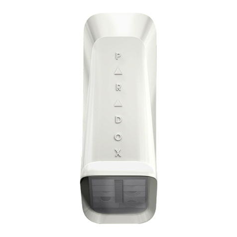
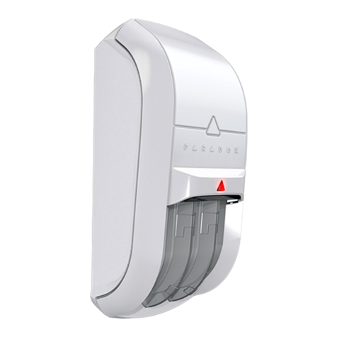
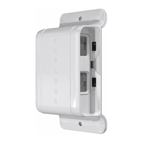
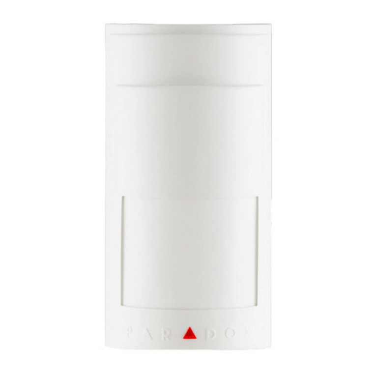
Paradox MG-PMD85 User manual

Outdoor Digital Dual-Optic
High-Performance PIR
(40kg/90lb True Pet Immunity)
V1.0
Reference & Installation Manual
MG-PMD85


Table of Contents
English............................................ 1
Installation............................................... 1
PCB Height Adjustment .......................... 2
LED Setting (DIP 1)................................. 3
Single/Dual Edge Processing (DIP 2) ..... 3
Powering the Detector............................. 4
Replacing the Batteries........................... 4
Sensitivity Settings.................................. 5
Walk-testing ............................................ 5
Signal Strength Test................................ 6
Alive Software ......................................... 7
Technical Specifications.......................... 7
Español......................................... 10
Instalación............................................. 10
Ajuste de la Altura de la PCI ................. 11
Configuración LED (DIP 1).................... 12
Procesamiento de Polaridad Simple /Doble
(DIP 2)................................................... 12
Encendido del Detector......................... 13
Cambio de Baterías .............................. 13
Configuración de la Sensibilidad........... 14
Prueba Caminando............................... 15
Prueba de Fuerza de la Señal .............. 15
Software Alive ....................................... 16
Especificaciones Técnicas.................... 16

Français........................................ 19
Installation............................................. 19
Ajustement de la hauteur de la carte de cir-
cuits imprimés ....................................... 20
Réglage de la DEL (commutateur DIP 1)...
21
Traitementsimple/divisé(commutateurDIP
2)........................................................... 22
Mise sous tension du détecteur ............ 22
Remplacement des piles....................... 23
Détermination de la sensibilité .............. 23
Essai de marche ................................... 24
Vérification de la puissance du signal... 25
Logiciel Alive ......................................... 26
Spécifications techniques...................... 26

Reference & Installation Manual 1n
English
Installation
At the recommended height of 2.1m (7ft) to 2.7m
(9ft) ± 10%, MG-PMD85 provides full coverage
from 1.5m (5ft) to 11m (35ft) as shown in Figure 5
on page 33. The MG-PMD85 includes a
weatherproof casing so it can be installed outside.
The
MG-PMD85
has been UL evaluated at
the 2.1m (7ft) mounting height only.
Avoid placing the detector within proximity of the
following sources of interference such as direct
sunlight, reflective surfaces and moving cars.
Do not touch the sensor surface as this
could result in a detector malfunction. If
necessary, clean the sensor surface using a
soft cloth with pure alcohol.
Avoid bending, cutting or altering the
antenna or mounting the detector near or on
metal, such as aluminum siding, as this may
affect signal transmission.
After selecting the detector's location, drill or punch
out holes for the screws (Figure 4 on page 32).

2 Magellan MG-PMD85
The
MG-PMD85
can also be mounted using
the Paradox Swivel Mount Bracket (469). The
swivel mount may allow for easier mounting. If
using the swivel mount, it is recommended that
you seal the space where the swivel mount is
connected to the back cover with some silicon
or with a rubber gasket to ensure that moisture
does not enter the detector.
The
MG-PMD85
has been UL evaluated at
the 2.1m (7ft) mounting height only.
PCB Height Adjustment
The MG-PMD85 is designed for optimal
performance at a height of 2.1m (7ft), but can be
installed lower or higher. After you have installed
the detector, ensure that the adjustable height
markings on the upper right of the PCB’s cover
inside the unit match the installation height.
For example, if the detector is installed at a
height of 2.1m (7ft), the PCB should then be
adjusted to 2.1m (7ft). Align the desired marking
(height) with the back cover’s plastic tab (Figure
1 on page 29 and Figure 2 on page 30).
If another installation height is called for, readjust
the PCB accordingly. Any PCB adjustments
should be followed by a walk-test of the
protected area. Walk-testing verifies that the
required coverage is in place.

Reference & Installation Manual 3n
The
MG-PMD85
has been UL evaluated at
the 2.1m (7ft) mounting height only.
Ensure that the unit’s front and back cover
are tightly joined together without any
spacing (around the rim of the unit) before
tightening the screw, otherwise the
weatherproof casing may be compromised
and moisture may enter the unit.
LED Setting (DIP 1)
This option enables or disables the red LED. The
red LED will illuminate for a period of four
seconds to indicate detected movement. The
motion detector performs a battery test every 12
hours. If the battery voltage is too low, the red
LED will flash at eight-second intervals and the
motion detector will send a low battery signal to
the receiver. A trouble will then be generated and
transmitted to the central monitoring station. The
red LED will flash rapidly when the motion
detector transmits a signal to the receiver.
DIP switch 1 OFF = LED deactivated
DIP switch 1 ON = LED activated (default)
Single/Dual Edge Processing (DIP 2)
This option determines the DSP (Digital Signal
Processing) of the detector. Single Edge
Processing should be used in normal
environments with minimal sources of

4 Magellan MG-PMD85
interference. Dual Edge Processing provides
better false alarm rejection if the detector is
placed near sources of interference that can
adversely affect it.
DIP switch 2 OFF = Dual Edge
DIP switch 2 ON = Single Edge (default)
DIP switches 3 and 4 are reserved for future
use.
Powering the Detector
1. Insert three “AA” batteries into the battery
holder while verifying polarity. Refer to Figure
2 on page 30.
2. Insert the battery holder into the back cover
and affix the battery cable to the battery
connector on the PCB. Refer to Figure 3 on
page 31.
After connecting the battery cable, a power-up
sequence will begin (lasting between 10 to 30
seconds). During this time, the red LED will
flash and the detector will not detect an open
zone or tamper.
Replacing the Batteries
1. Disconnect the battery cable from the battery
connector of the PCB.
2. Remove the battery holder from the back
cover and remove the old batteries.
3. Press and release the tamper switch to
ensure that the unit has powered down.

Reference & Installation Manual 5n
4. Follow the steps outlined in Powering the
Detector above.
Sensitivity Settings
MG-PMD85 features adjustable sensitivity.
Adjust from 1 to 10 where 1 is the lowest setting
and 10 the highest. Remove the front cover and
with a screwdriver, turn the trimpot clockwise to
increase the detector’s sensitivity or
counterclockwise to decrease it.
Depending on the sensitivity setting, an
alarm condition can be generated between
0.25 sec. (highest) and 2 sec. (lowest) after
the actual movement.
Viewing Sensitivity Settings
Remove the cover to view how many times
the LED flashes, then adjust the setting
accordingly. The LED flashes a consecutive
amount of times to show the setting. Thus if
the sensitivity is set to 6, the LED flashes 6
times. If no action is performed after three
minutes, the LED will exit sensitivity display
mode and return to its normal operation.
Walk-testing
At 20°C (68°F), open and close the cover to put
the detector into Walk-Test mode. The Walk-Test
mode will stay active for three minutes.

6 Magellan MG-PMD85
At the highest sensitivity setting and in Single
Edge Processing mode, you should not be able
to cross more than one complete zone
(consisting of 2 beams, left and right sensor
detecting elements) in the coverage area with
any kind of movement; slow/fast walking or
running.
At the lowest sensitivity setting, the amount of
movement required to generate an alarm is
doubled. The approximate width of a full beam at
11m (35ft) from the detector is 1.8m (6ft). To
walk-test, move across the detection path, not
toward the detector.
After a power up, the detector will automatically
enter Walk-Test mode for three minutes.
Signal Strength Test
In order to verify the receiver’s reception of the
motion detector’s signal, perform a signal
strength test before finalizing the installation of
the MG-PMD85. Prior to performing the test,
make sure that the batteries have been inserted
into the battery holder to power the detector. Also
verify that the motion detector has been
assigned to a zone. For more information on
signal strength tests and zone programming,
refer to the appropriate receiver’s
Reference &
Installation Manual
. If the transmission is weak,
Reference & Installation Manual 7n
just moving the detector by a few inches can
greatly improve the reception. If the signal is still
weak, it is recommended that the detector be
moved to another location.
Alive Software
If the motion detector transmits two alarm signals
(LED on for 4 seconds) within a five minute
period, the detector will fall into Energy Save
mode where the detector will not transmit any
alarm signals for approximately 3 minutes. Due
to the motion detector’s Alive software, the red
LED continues to flash to indicate a detection
even when in Energy Save mode. Once the
three-minute Energy Save mode ends, the
detector will return to normal operation.
If the detector’s cover is removed and then
replaced while in Energy Save mode, the first
detection will trigger an alarm signal.
Technical Specifications
Sensor type: Dual Element Infrared (x 2)
Sensor geometry: Rectangular
Coverage: 11m x 11m (35ft x 35ft) 90°
viewing angle
Installation height: 2m to 2.7m (7ft to 9ft)*
Operating temperature: 0°C to +49°C (32°F to +120°F)
Animal immunity: 40kg (90lbs)
Power: 3 x “AA” alkaline batteries
RF frequency: 433** or 868***MHz
Lens: 2nd generation Fresnel lens,
LODIFF®, segments

8 Magellan MG-PMD85
Transmitter range: 35m (115ft) with MG-6060; 70m
(230ft) with MG-RCV3; typical in a
residential environment
Tamper switch: Yes
Detection speed: 0.76m/s (30in/s)
Battery life
†
: 4 years
* The MG-PMD85 has been UL evaluated at a mounting height of 2.1m (7ft) only.
** FCC ID: KDYMGPMD85 Canada: 2438A-MGPMD85
The MG-PMD85 complies with part 15 of the FCC rules. Operation is subject to the following
two conditions: (1) This device may not cause harmful interference, and (2) This device must
accept any interference received, including interference that may cause undesired operation.
*** 868MHz (only) is not UL approved.
†
Tested at 25°C. Battery life expectancy will vary according to the amount of traffic
(movement) the detector has processed and the temperature outdoors. A higher check-in
time interval and higher traffic will lower battery life. In colder temperatures, the capacity of
alkaline batteries is reduced.
Warranty
Paradox Security Systems Ltd. (“Seller”) warrants its products to be free from defects in materials
and workmanship under normal use for a period of one year. Except as specifically stated herein,
all express or implied warranties whatsoever, statutory or otherwise, including without limitation,
any implied warranty of merchantability and fitness for a particular purpose, are expressly
excluded. Because Seller does not install or connect the products and because the products may
be used in conjunction with products not manufactured by Seller, Seller cannot guarantee the
performance of the security system and shall not be responsible for circumstances resulting from
the product’s inability to operate. Seller obligation and liability under this warranty is expressly
limited to repairing or replacing, at Seller's option, any product not meeting the specifications.
Returns must include proof of purchase and be within the warranty period. In no event shall the
Seller be liable to the buyer or any other person for any loss or damages whether direct or indirect
or consequential or incidental, including without limitation, any damages for lost profits stolen
goods, or claims by any other party, caused by defective goods or otherwise arising from the
improper, incorrect or otherwise faulty installation or use of the merchandise sold.
Notwithstanding the preceding paragraph, the Seller’s maximum liability will be strictly limited to
the purchase price of the defective product. Your use of this product signifies your acceptance of
this warranty.
BEWARE: Dealers, installers and/or others selling the product are not authorized to modify this
warranty or make additional warranties that are binding on the Seller.
© 2004-2005 Paradox Security Systems Ltd. All rights reserved.
Specifications may change without prior notice. One or more of the following US patents may
apply: 6215399, 6111256, 5751803, 5721542, 5287111, 5119069, 5077549, 5920259, 5886632.
Canadian and international patents may also apply. LODIFF® lens: patent #4,787,722 (U.S.).
Magellan is a trademark or registered trademark of Paradox Security Systems Ltd. or its affiliates
in Canada, the United States and/or other countries.

Manuel d’installation et de référence 9n
LODIFF® is a registered trademark of Fresnel Technologies Inc.
For technical support in Canada or the U.S., call 1-800-791-1919 for English or 1-866-912-0600
for French, Monday to Friday from 8:00AM to 8:00PM EST. For technical support outside Canada
and the U.S., call 00-1-450-491-7444, Monday to Friday from 8:00AM to 8:00PM EST.
Please feel free to check out our Web site at www.paradox.ca.
Changes and modifications on equipment not expressly approved by Paradox Security Systems
could void the user's authority to operate the equipment.

10 Magellan MG-PMD85
Español
Instalación
A la altura de 2.1m (7ft) a 2.7m (9ft) ±10%, el MG-
PMD85 da una cobertura total de 1.5 m (5ft) a 11
m (35ft) como muestra la Figura 5 en pág. 33. El
MG-PMD85 incluye una caja resistente a
intemperies para su instalación en exteriores.
El
MG-PMD85
ha sido verificado por UL a la
altura de instalación de 2.1m (7ft) solamente.
Evite ubicar el detector cerca de fuentes de
interferencia como luz solar directa, superficies
reflectantes y carros en movimiento.
No toque la superficie del sensor pues
puede causar un mal funcionamiento. De
ser necesario, limpie la superficie del
sensor con un paño delicado y alcohol puro.
Evite doblar, cortar o alterar la antena o
montar el detector cerca de o sobre metal,
como recubrimiento de aluminio, pues esto
puede afectar la transmisión de la señal.
Luego de decidir la ubicación del detector, haga los
agujeros para los tornillos (Figura 4 en pág. 32).

Manuel d’installation et de référence 11n
El
MG-PMD85
también puede ser montado
usando el Soporte de Montaje Giratorio de
Paradox (469). El soporte giratorio favorece un
fácil montaje. Si se usa, se recomienda sellar
el espacio donde el soporte giratorio está
conectado a la cubierta posterior con silicona o
con una junta de caucho, para asegurar que la
humedad no penetre en el detector.
El
MG-PMD85
ha sido verificado por UL a la
altura de instalación de 2.1m (7ft) solamente.
Ajuste de la Altura de la PCI
El MG-PMD85 está diseñado par una operación
óptima a una altura de 2.1m (7ft), pero puede ser
instalado a mayor o menor altura. Luego de
instalar el detector, asegúrese que las marcas de
altura en la parte superior derecha del interior de
la cubierta de la placa de circuito impreso (PCI)
coinciden con la altura de instalación.
Por ejemplo, si se instala el detector a una altura
de 2.1m (7ft), la PCI debe entonces ser ajustada
a 2.1m (7ft). Alinee la marca de altura deseada
con la lengüeta plástica de la cubierta trasera
(Figura 1 en pág. 29 y Figura 2 en pág. 30).
De necesitarse otra altura de instalación, ajuste
la PCI en consecuencia. Todo ajuste a la PCI
debe ser seguido de una prueba caminando en
el área protegida. La prueba caminando sirve
para verificar si se tiene la cobertura deseada.

12 Magellan MG-PMD85
El
MG-PMD85
ha sido verificado por UL a la
altura de montaje de 2.1m (7ft) solamente.
Antes de atornillar, asegúrese que las
cubiertas delantera y trasera de la unidad
estén bien encajadas y sin más espacios
que el del marco de la unidad. En otro caso,
la caja a prueba de intemperies podría verse
afectada y la humedad podría infiltrarse.
Configuración LED (DIP 1)
Esta opción habilita o deshabilita la luz LED roja.
La luz LED roja se enciende 4 segundos para
indicar la detección de movimiento. El detector
de movimiento efectúa una prueba de batería
cada 12 horas. Si el voltaje de la batería es muy
bajo, la luz LED roja parpadeará a intervalos de
8 seg. y el detector de movimiento enviará una
señal de batería baja al receptor. Se generará
entonces un fallo que será transmitido a la
central receptora. La luz LED roja parpadeará
rápidamente cuando el detector de movimiento
transmita una señal al receptor.
Interruptor DIP 1 OFF = LED desactivada
Interruptor DIP 1 ON = LED activada (de fábrica)
Procesamiento de Polaridad Simple /
Doble (DIP 2)
Esta opción determina el Procesamiento Digital
de Señales (DSP) del detector. Se debe usar el

Manuel d’installation et de référence 13n
Procesamiento de Polaridad Simple en
ambientes normales con mínimas fuentes de
interferencia. El Procesamiento de Polaridad
Doble ofrece un mayor rechazo a falsas alarmas
si el detector está ubicado cerca de fuentes de
interferencia que pueden perjudicarlo.
Interr. DIP 2 OFF = Polaridad Doble
Interr. DIP 2 ON = Polaridad Simple (de fábrica)
Los interruptores DIP 3 y 4 están reservados
para uso futuro.
Encendido del Detector
1. Ponga 3 baterías “AA” en su compartimiento
verificando la polaridad. Ver la Figura 2 en
pág. 30.
2. Inserte el compartimiento en la cubierta
trasera y fije el cable de batería en el conector
de batería de la PCI. Ver Figura 3 en pág. 31.
Luego de conectar el cable de la batería,
empezará una secuencia de encendido (que
durará de 10 a 30 segundos). Durante este
tiempo, la luz LED roja parpadeará y el detector
no detectará zonas abiertas ni sabotajes.
Cambio de Baterías
1. Desenchufe el cable de batería del conector
de batería en la PCI.
2. Quite el compartimiento de baterías de la
cubierta trasera y saque las viejas baterías.
3. Pulse y suelte el interruptor antisabotaje para
asegurarse que la unidad ha sido apagada.

14 Magellan MG-PMD85
4. Siga los pasos indicados arriba en Powering
the Detector.
Configuración de la Sensibilidad
El MG-PMD85 tiene la opción de ajuste de
sensibilidad. Se puede ajustar de 1 a 10 donde 0
es el ajuste más bajo y 10 el más alto. Quite la
cubierta frontal y con un destornillador, gire el
potenciómetro de izquierda a derecha para
aumentar la sensibilidad del detector o de
derecha a izquierda para disminuirla.
Según el ajuste de sensibilidad, se puede
generar una alarma entre 0.25 seg. (mayor
sensibilidad) y 2 seg. (menor sensibilidad)
luego del movimiento en curso.
Ver la Configuración de la Sensibilidad
Quite la cubierta para ver cuántasveces la luz
LED parpadea y ajuste la sensibilidad en
consecuencia. Para mostrar la configuración,
la luz LED parpadea un número consecutivo
de veces. Así, si la sensibilidad es de 6, el
LED parpadeará 6 veces. De no efectúarse
una acción en el lapso de 3 minutos, la luz
LED saldrá del modo visualización de
sensibilidad y volverá a su operación normal.

Manuel d’installation et de référence 15n
Prueba Caminando
A 20 °C (68 °F), abra y cierre la cubierta para
que el detector entre al modo de Prueba
Caminando. Este modo estará activo 3 minutos.
En la mayor sensibilidad y en el modo de
Procesamiento de Polaridad Simple, no se debe
poder cruzar más de una zona completa (de 2
haces, elementos de detección izquierdo y
derecho del sensor) en el área protegida con
ningún tipo de movimiento; caminando despacio
/rápido o corriendo.
En la mínima sensibilidad, se requiere el doble
de movimiento para generar una alarma. El
ancho aproximado de un haz completo a 11m
(35ft) del detector es de 1.8m (6ft). Al efectuar la
prueba caminado, camine siempre atravesando
la trayectoria de detección, no hacia el detector.
Después del encendido, el detector entrará
automáticamente al modo de prueba
caminando durante 3 minutos.
Prueba de Fuerza de la Señal
Para verificar si el receptor recibe la señal del
detector de movimiento, efectúe una prueba de
fuerza de señal antes de terminar la instalación
del MG-PMD85. Antes de realizar la prueba,
asegúrese que las baterías fueron insertadas en
su compartimiento para poder encender el
detector. Verifique también que el detector de

16 Magellan MG-PMD85
movimiento fue asignado a una zona. Para más
información acerca de la prueba de fuerza de
señal y la programación de zonas, vea el
Manual
de Instalación y Consulta
del receptor
correspondiente. Si la transmisión es débil,
mover el detector sólo unos pocos centímetros
puede mejorar de manera considerable la
recepción. Si la señal aún es débil, se
recomienda cambiar de lugar al detector.
Software Alive
Si el detector de movimiento envía 2 señales de
alarma (LED iluminado 4 seg) al interior de 5
minutos, el detector entrará en Modo de Ahorro
de Energía durante el cual no enviará ninguna
señal de alarma por 3 minutos aprox. Gracias al
Software Alive, la luz LED roja del detector
seguirá parpadeando para indicar la detección
incluso cuando esté en este modo. Al término de
los 3 minutos del Modo de Ahorro de Energía, el
detector retoma su funcionamiento normal.
Si se quita y repone la cubierta del detector
durante el Modo de Ahorro de Energía, la
primera detección activa una señal de alarma.
Especificaciones Técnicas
Tipo de Sensor: Infrarrojo de Doble Elemento (x 2)
Geometría del Sensor: Rectangular
Cobertura: 11m x 11m (35ft x 35ft) ángulo de
visión de 90°
Table of contents
Languages:
Other Paradox Accessories manuals

Paradox
Paradox Digital Vision 525D User manual

Paradox
Paradox NV780MR User manual

Paradox
Paradox ENVY NVX80 User guide

Paradox
Paradox NVR780 User manual

Paradox
Paradox DB7 User manual

Paradox
Paradox GS250 User manual

Paradox
Paradox DCT6 User manual

Paradox
Paradox NV35M User manual

Paradox
Paradox DB7 Original operating instructions

Paradox
Paradox NV75M Guide
Popular Accessories manuals by other brands

Rutenbeck
Rutenbeck TC IP 1 operating instructions

STEINEL PROFESSIONAL
STEINEL PROFESSIONAL HF 3600 Information

Aromacare
Aromacare Gantha TA-307 user manual

Knick
Knick SensoGate WA 133 Series user manual

Leviton
Leviton lumina INSTALLATION AND QUICK START SHEET

Eaton
Eaton xComfort CTEU-02/0 Series Assembly instructions