PARAGON OUTDOOR OH-R744S User manual

CSA/ANSI 83.26-2020
CSA 2.37-2020
5016039
Round Flame Tower Heater
OH-R744S-Stainless Steel
OH-R744B-Heritage Bronze
OH-R744BL-Black

Please read and understand this entire manual before attempting to assemble, operate or install the product.
This manual contains important information about the assembly, operation and maintenance of this patio heater.
General safety information is presented in these first few pages and is also located throughout the manual.
Keep this manual for future reference and to educate new users of this product. This manual should be read
in conjunction with the labeling on the product. Safety precautions are essential when any mechanical or pro-
pane-fueled equipment is involved. These precautions are necessary when using, storing and servicing this
item. Using this equipment with the respect and caution demanded will reduce the possibilities of personal
injury or property damage. The following symbols shown below are used extensively throughout this manual.
Always heed these precautions, as they are essential when using any mechanical or fueled equipment.
SAFETY INFORMATION
DANGER
DANGER indicates an imminently hazardous
situation which, if not avoided will result in
death or serious injury.
WARNING
WARNING indicates an imminently hazardous
situation which, if not avoided will result in
death or serious injury.
DANGER
Failure to comply with the precautions and
instructions provided with this heater can
result in death, serious bodily injury and
property loss or damage from hazards of fire,
explosion, burn, asphyxiation and/or carbon
monoxide poisoning. Only persons who can
understand and follow the instructions should
use or service this heater.
• EXPLOSION - FIRE HAZARD
•Keep solid combustibles, such as building
materials, paper or cardboard, a safe distance
away from the heater as recommended by the
instructions.
•Provide adequate clearances around air
openings into the combustion chamber.
•Never use the heater in spaces which do or
may contain volatile or airborne combustibles,
or products such as gasoline, solvents, paint
thinner, dust particles or unknown chemicals.
•During operation, this product can be a source
of ignition. Keep heater area clear and free
from combustible materials, gasoline, paint
thinner, cleaning solvents and other flammable
vapors and liquids. Do not use heater in areas
with high dust content. Minimum heater clear-
ances from combustible materials: 3 feet from
the sides & 3 feet from the top.
DANGER
DANGER
If you smell gas:
1. Shut off gas to the appliance.
2. Extinguish any open flame.
3. If odor continues, keep away from the
appliance and immediately call your gas
supplier or fire department
WARNING
Do not store or use gasoline or other flam-
mable vapors and liquids in the vicinity of this
or any other appliance. An LP-cylinder not
connected for use shall not be stored in the
vicinity of this or any other appliance.
WARNING
Certain materials or items, when stored under
the heater, will be subjected to radiant heat and
could be seriously damaged.
CAUTION
CAUTION indicates an imminently hazardous
situation which, if not avoided, may result
in minor or moderate personal injury, or
property damage.
WARNING
BURN HAZARD
• Never leave heater unattended
when hot or in use.
•Keep out of reach of children.

DANGER
• CARBON MONOXIDE HAZARD
•This heater is a combustion appliance.
All combustion appliances produce carbon
monoxide (CO) during the combustion
process. This product is designed to produce
extremely minute, non-hazardous amounts of
CO if used and maintained in accordance with
all warnings and instructions. Do not block air
flow into or out of the heater.
•Carbon Monoxide (CO) poisoning produces
flu-like symptoms, watery eyes, headaches,
dizziness, fatigue and possibly death. You
can’t see it and you can’t smell it. It’s an
invisible killer. If these symptoms are present
during operation of this product, get fresh air
immediately!
•For outdoor use only.
•Never use inside house, or other unventilated
or enclosed areas.
•This heater consumes air (oxygen). Do not
use in unventilated or enclosed areas to avoid
endangering your life.
WARNING
Improper installation, adjustment, alteration,
service or maintenance can cause property
damage, injury or death. Read the installation,
operation and maintenance instructions
thoroughly before installing or servicing
this equipment.
DANGER
• EXPLOSION - FIRE HAZARD
•Never store propane near high heat, open
flames, direct sunlight, other ignition sources
or where temperatures exceed 120 degrees
F (49°C).
•Propane vapors are heavier than air and can
accumulate in low places. If you smell gas,
leave the area immediately.
•Never install or remove the propane cylinder
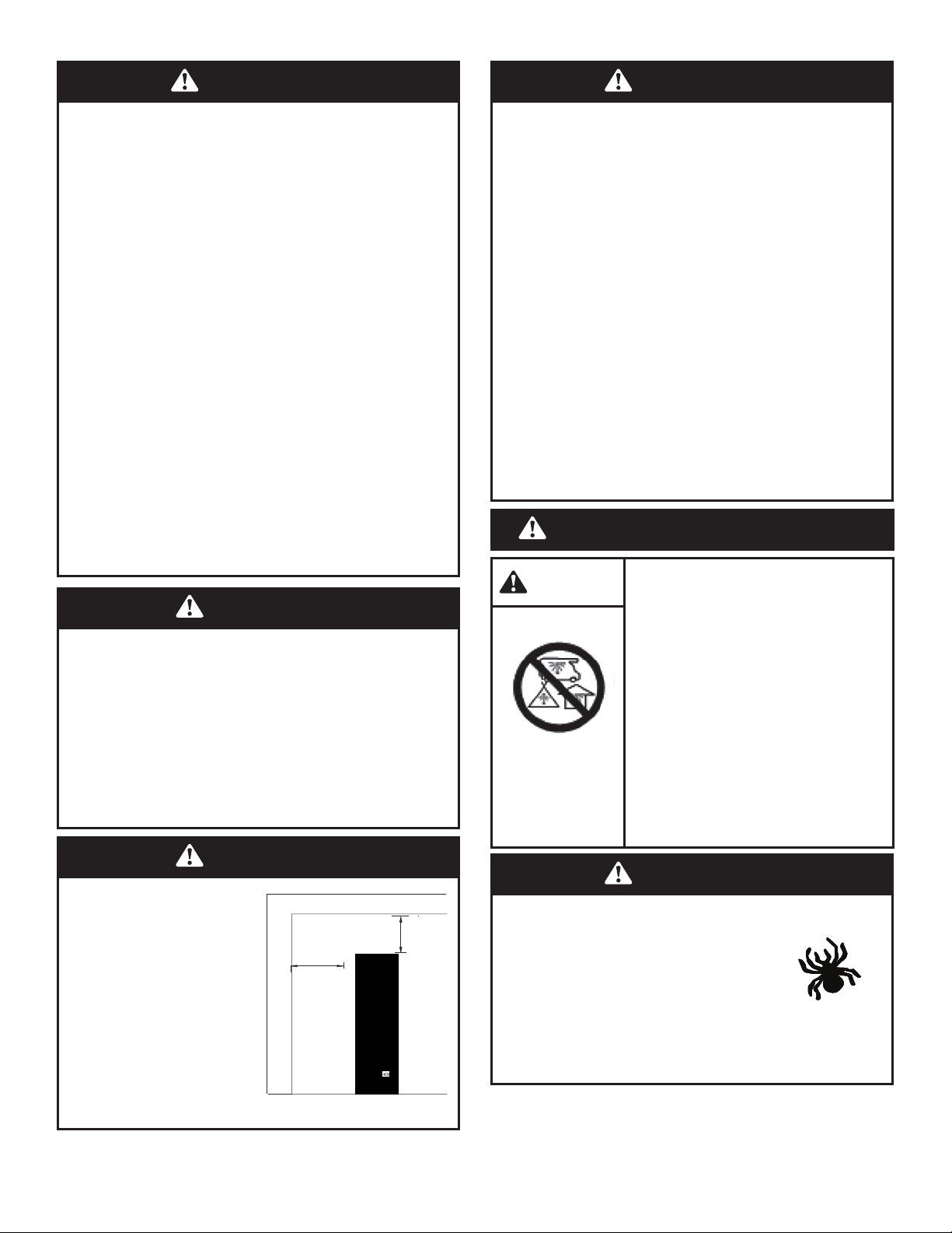
•This heater is red hot during use and can
ignite flammables that are too close to the
burner. Keep flammables at least 3 feet from
sides & 3 feet from top. Keep gasoline and
other flammable liquids and vapors well
away from heater.
•Store the propane cylinder outdoors in
a well-ventilated space out of reach of
children. Never store the propane cylinder
in an enclosed area (house, garage etc.). If
heater is to be stored indoors, disconnect
the propane cylinder for outdoor storage.
WARNING
We cannot foresee every use which may be
made of our heaters.
Check with your local fire safety authority if
you have questions about heater use.
Other standards govern the use of fuel gases
and heat producing products for specific uses.
Your local authorities can advise you about
these.
If no local codes exist, follow National Fuel
Gas Code, ANSI Z223.1. In Canada, installation
must conform to local codes. If no local codes
exist, follow the current National standards of
CANADA CAN/CGA-B 149.2.
WARNING
California Proposition 65
Combustion by-products produced when using
this product contain chemicals known to the
State of California to cause cancer, birth defects
and other reproductive harm.
CAUTION
SERVICE SAFETY
• Keep all connections and fittings clean. Make
sure propane cylinder valve outlet is clean.
•During set up, check all connections and
fittings for leaks using soapy water. Never use
a flame.
•Use as a heating appliance only. Never alter in
any way or use with any device.

WARNING
• For outdoor use
ONLY.
• An amply ventilated
area must have a
minimum of 25 %
of the surface area
open.
• The surface area is
the sum of the walls
surface.
W A L L
48"
4'
48"
4'
CEILING
WARNING
• This product is fueled by propane gas.
Propane gas is invisible, odorless and
flammable. An odorant is normally added to
help detect leaks and can be described as a
“rotten egg” smell. The odorant can fade over
time so leaking gas is not always
detectable by smell alone.
•Propane gas is heavier than air and
leaking propane will sink to the lowest
level possible. It can ignite by ignition sources
including matches, lighters, sparks or open
flames of any kind many feet away from the
original leak. Use only propane gas set up for
vapor withdrawal.
•Store or use propane gas in compliance with
local ordinances and codes or with ANS/NFPA
58. Turn off propane when not in use.
WARNING
• Alert children and adults to the hazards
of high surface temperatures. Stay away
from these surfaces to avoid burning skin
or igniting clothing.
•Carefully supervise young children when in the
vicinity of the heater.
•Do not hang clothing or any other flammable
materials from the heater, or place on or near
the heater.
•Replace any guard or protective device
removed for servicing the appliance prior
to placing back in service.
•Installation and repair should be done by a
qualified service person. The heater should
be inspected before use and annually by
a qualified service person. More frequent
cleaning may be required as necessary. It
is imperative that the control compartment,
burners and circulating air passageway of
the appliance be kept clean.
CAUTION
SERVICE SAFETY
• Keep all connections and fittings clean. Make
sure propane cylinder valve outlet is clean.
•During set up, check all connections and
fittings for leaks using soapy water. Never use
a flame.
•Use as a heating appliance only. Never alter in
any way or use with any device.
WARNING: For Outdoor Use Only
1
IMPORTANT: Please read this manual carefully before beginning assembly of this product.
Keep this manual for future reference.
5016039
Assembly Instruction
& User's Manual
87IN Height LP Patio Heater
ITEM NO. 13684811
DANGER CARBON MONOXIDE
HAZARD
This appliance can produce
carbon monoxide which has
no odor.
Using it in an enclosed space
can kill you.
Never use this appliance in
an enclosed space such as
a camper, tent, car or home.
WARNING
Spiders and insects can nest in
burner or orifices. This dangerous
condition can damage heater and
render it unsafe for use.
Clean burner holes by using a
heavy-duty pipe cleaner.
Compressed air may help clear
away smaller particles.

A
AA
B
C
D
E
F
G
K
J
I
H
L
PART DESCRIPTION QUANTITY
AA Reflector Cover 1
A Reflector 1
B Emitter 1
C Support 3
D Protective Guard 3
E Ruby Quartz Glass Tube 1
F Burner Ignition Plate 1
G Control Box Casing 1
H Gas Hose & Regulator 1
I Back Panel 1
J Front Door Panel 1
K Wheel Kit 1
L Base Plate 1
Parts List
AAA Alkaline
Battery
Qty. 2
(Not included)
QQ
Teon Tape
Qty. 1
TT
MM
Screw M8 x 15 mm
Qty. 16
DD
Wrench
Qty. 1
OO
Bolt M8 x 15mm
Qty. 2
EE
Nut M8
Qty. 11
HH
PP
Philips screwdriver
Qty. 1
RR
Ceramic Rope with Attachment Clips
Qty. 2
FF
Screw M8 x 30 mm
Qty. 1
Screw M8 x 10 mm
Qty. 12
ADDITIONAL REQUIRED HARDWARE
• Adjustable opening wrench (2) 20 cm (8") long
• Slip joint pliers 23 cm (9") long
• Philips screwdriver w/ medium blade
• Spray bottle of soap solution for leakage test
PACKAGE CONTENTS
INCLUDED HARDWARE
UU
DAlkaline
Battery
Qty. 1
(Not included)

1. REFLECTOR ASSEMBLY:
First please ensure all transit protection
(foam, cardboard, bubble wrap, etc.) is
removed. Carefully put the ruby quartz glass
tube aside after removing the bubble wrap
and foam material.
Verify 2 nuts M8 (HH) installed on each stem.
Unscrew top nut on each stem to desired height
as shown (fig. 1-A).
Place reflector over stems as shown (fig. 1-B)
and hand tighten 1 M8 nut (HH) per stem.
2. GUARD REMOVAL:
Remove one protective steel guard by
unscrewing 4pcs M5x10mm as show in fig 2.
Nut M8 Qty 6
(Already assembled)
Nut M8 Qty 3
Wrench Qty 1
Assembly Instructions
1-B
1-A
2
MM
HH
ASSEMBLY INSTRUCTIONS
Hardware Used
Hardware Used
Before beginning assembly of product, make sure all parts are present. Compare parts with package contents
list and hardware contents above. If any part is missing or damaged, do not attempt to assemble the product.
Contact customer service for replacement parts.
Estimated Assembly Time: 45 minutes
Tools Required for Assembly (not included):
Phillips screwdriver w/medium blade. Leak Detection Solution.
PREPARATION
Remove one guard only,
remove by unscrewing 4 pieces M5 x 10mm
D

3. Install reflector to support with M8 screws
(Qty. 6)
4. Wrap the ceramic rope with clips (RR)
around the top and bottom of the Ruby
Quartz Glass Tube (E) and attach clips to
glass. (fig 4-A)
Then place the Glass tube with both pieces of
ceramic rope into glass tube holder at bottom.
(fig. 4-B)
Assembly Instructions
3
4-B
4-A
ASSEMBLY INSTRUCTIONS
Hardware Used
Hardware Used
Wrench Qty 1
RR
E

ASSEMBLY INSTRUCTIONS
6.Tighten the Nut M8 on the reflector.Then
use Bolt M8 to tighten the small hat on top of
the reflector.
6
ortionTop p
panelsmBotto
kitWheel
plateBase
Hardware Used
2
Top View
Nut M8
Qty.
3
Bolt M8×30 mm
Qty.
1
Wrench
Qty. 1
Philips screwdriver
Qty. 1
9
Assembly Instructions
Note: Before installation, please wear gloves,
press the lower seat of the glass tube, let it
loose, then install the glass tube!
5. Loosen the top nut M8 x3 under the
reflector in clockwise direction. Then lift the
emitter by one hand and place the glass tube
inside. Gently pull downward on the emitter,
and tighten the nut M8 x3 under the reflector
in a counterclockwise direction.
6. Tighten the nuts M8 x3 (HH) on the reflector.
These were hand tightened from step 1.
Use bolt M8 (FF) to attach reflector cover (AA)
on top of the reflector as shown in fig 6.
(from step 1)
x3
AA
AA
Reflector Cover
Qty. 1

Hardware Used
DD x 5
x 1
PP Philips
screwdriver
Screw M8×15 mm
Hardware Used
DD x 5
x 1
PP Philips
screwdriver
Screw M8×15 mm
7
philips screwdriver.
designated 90 degree metal brackets with a
installing (5) M8×15 screws through the
and connect them together by securely
7. Align bottom panel on top of base plate
ASSEMBLY INSTRUCTIONS
8
philips screwdriver.
designated 90 degree metal brackets with a
installing (5) M8×15 screws through the
and connect them together by securely
8. Align top portion on top of bottom panel
10
Bottom panel
Assembly Instructions
8. Align top portion on top of bottom panel
and connect them together by securely
installing (5) M8x15 screws through the
designated 90 degree metal brackets with
a philips screwdriver.
Note: These 4 metal brackets are included with
the hardware and must be installed into the
back panel using the M1x12mm screws.
Hardware Used
DD x 5
x 1
PP Philips
screwdriver
Screw M8×15 mm
Hardware Used
DD x 5
x 1
PP Philips
screwdriver
Screw M8×15 mm
7
philips screwdriver.
designated 90 degree metal brackets with a
installing (5) M8×15 screws through the
and connect them together by securely
7. Align bottom panel on top of base plate
ASSEMBLY INSTRUCTIONS
8
philips screwdriver.
designated 90 degree metal brackets with a
installing (5) M8×15 screws through the
and connect them together by securely
8. Align top portion on top of bottom panel
10
Bottom panel
Assembly Instructions
Note:These 4 metal brackets are included with
the hardware and must be installed into the
back panel using the M6x12mm screws.
8
8

Assembly Instructions
ASSEMBLY INSTRUCTIONS
Hardware Used
MM
MM
D
x 12
x 1
PP Philips
screwdriver
Screw M5×10 mm
9
10
any high temperature surfaces, or it may melt
WARNING! Ensure the hose does not contact
10. Install regulator to the heater.
.
secure it with all (12) of the M5×10 screws
in to their original support slots accordingly.
hanging it on the upper support slots.Next tightly
9 .Re-install the protective steel guard(D) by
and leak, causing a fire.
11
10. Wrap gas intake with teflon tape (TT)
in clockwise direction (fig. 10-A).
Then connect gas hose (H) (fig. 10-B)
The knob on the LP tank must be closed.
Make sure that the knob is turned clockwise
to a full stop. The cylinder supply sysem must
be arranged for vapor withdrawl. Check that
the control knob on the control unit is turned
off. Hold old the regulator in one hand and
insert the nipple into the valve outlet. Be sure
the nipple is centered in the valve outlet. The
coupling nut connects to the large outside
threads on the valve outlet. Hand-tighten the
coupling nut clockwise until it comes to a full
stop. Firmly tighten by hand only. (fig. 10-C)
To Disconnect: Fully close the tank by
turning clockwise until the regulator
assembly detaches clockwise. Turn the
coupling nut counterclockwise.
10-A 10-B
10-C
H
TT

Assembly Instructions
Regulator / Cylinder
connection
12. Leak testing: See leak testing diagram for areas to check. Turn all
burner controls to the off position. Turn gas supply valve on.
Brush a half-and-half solution of liquid soap and water onto all joints and
connections of the regulator, hose, manifolds and valves.
Bubbles will indicate a gas leak. Either tighten the loose joint or have the
part replaced with one recommended by the Customer Care department
and have the patio heater inspected by a certified gas installer.
WARNING
A leak test must be performed annually and
each time a cylinder is hooked up or if a part
of the gas system is replaced, and whenever
any gas components are being replaced
or serviced.
Leak Check Diagram
WARNING
If the leak cannot be stopped,
immediately shut off the gas
supply, disconnect it, and have
the patio heater inspected by a
certified gas installer or dealer.
Do not use the patio heater until
the leak has been corrected.
WARNING
Do not smoke while performing
this test, and remove all sources
of ignition.
WARNING
A leak test must be performed annually and
each time a cylinder is hooked up or if a part
of the gas system is replaced, and whenever
any gas components are being replaced
or serviced.
WARNING
Never use an open flame to check for gas leaks.
Be certain no sparks or open flames are in the
area while you check for leaks. Sparks or open
flames will result in a fire or explosion, damage
to property, serious bodily injury, or death.
WARNING
If the leak cannot be stopped,
immediately shut off the gas
supply, disconnect it, and have
the patio heater inspected by a
certified gas installer or dealer.
Do not use the patio heater until
the leak has been corrected.
WARNING
Do not smoke while performing
this test, and remove all sources
of ignition.
WARNING
Ensure the hose does not contact any high
temperature surfaces, or it may melt and leak
causing a fire.
WARNING
Ensure the hose does not contact any high
temperature surfaces, or it may melt and leak
causing a fire. After the cylinder is placed inside
the heater, secure the cylinder with block belt
tightly.

Assembly Instructions
ASSEMBLY INSTRUCTIONS
Standard 20 lb. tank
11
handling code, B149.2.
lation Code, CSA B149.1, or propane storage and
ANSI Z223.1/NFPA54, natural gas and propane Instal-
the absence of local codes,with national fuel gas code,
The installation must conform with local codes, or in
assembly supplied with the appliance must be used.
full input rating. The pressure regulator and hose
required input rating for a heater at ratings less than
adjustment. The minimum hourly of 16,000 Btu/hr is
supply pressure: 5 psi is required for purpose of input
supply pressure: 250 psi. The minimum inlet gas
or any other enclosed area. The maximum inlet gas
installed and must not be stored in a building, garage
disconnected cylinder must have dust caps tightly
well-ventilated area out of the reach of children. A
appliance. A cylinder must be stored outdoors in a
the cylinder is disconnected and removed from the
Storage of an appliance indoors is permissible only if
department should have this book.
Propane Installation Code. Your local library or fire
ANSI/NFPA 58 or CSA B149.1, Natural Gas and
storage and handling of liquefied petroleum gas,
supply system. See chapter 12 of the standard for
Use this heater only with a propane vapor withdrawal
standard 20 lb. propane cylinder only.
propane gas and cylinder are sold separately.Use a
11. Connect hose and regulator to cylinder.The
12
1
12
13
WARNING
After the cylinder is placed inside the heater,
secure the cylinder with block belt tightly.
13. Install wheel kit to base plate by inserting
(2) x Bolt M8 x 15mm through the wheel kit and
base plate and securing them with (2) x Nut M8
(use supplied wrench to tighten).
Hardware Used
Wrench
Qty. 1
OO
Bolt M8 x 15mm
Qty. 2
EE
Nut M8
Qty. 2
HH
OPERATION INSTRUCTIONS
DANGER
&$5%210212;,'(+$=$5'
)RURXWGRRUXVHRQO\1HYHUXVHLQVLGHKRXVHRURWKHU
Hardware Used
AAA Alkaline Battery x 2
QQ
(Not included)
Basic IR control
If the appliance does not operate properly, switch off gas and refer to the problems
checklist at the rear of the manual. If the appliance can not be made to operate
correctly, contact your local gas supplier.
Temperature UP
ON/OFF
POWER
2. Closethe
lid.
3. Returnthe side panelin
place.
Temperature DOWN
Put 2 AAA batteries in the battery compartment (back)
1. open the cover of the battery box on the left
side of the controller and insert one D-type
battery (flashlight battery DC1.5v, each battery).
Considering the correct polarity.
UU DAlkaline
Battery x 1
(Not included)

OPERATION INSTRUCTIONS
Operation Instructions
XQYHQWLODWHGRUHQFORVHGDUHDV7KLVKHDWHUFRQVXPHVDLU
R[\JHQ'RQRWXVHLQXQYHQWLODWHGRUHQFORVHGDUHDVWR
DYRLGHQGDQJHULQJ\RXUOLIH
Figure 1
,JQLWHU 9DULDEOH
FRQWURONQRE
Figure 2
be lit before main burner can be started.
Note: This heater is equipped with a pilot light that allows for safer startups and shutdowns. Pilot must
/LJKWLQJ
UHSODFHPHQWKRVHDVVHPEO\VSHFLILHGE\PDQXIDFWXUHU
VKRXOGEHOHDNWHVWHG,IWKHKRVHOHDNVLWPXVWEHUHSODFHGSULRUWRRSHUDWLRQ2QO\XVHWKH
,QVSHFWWKHKRVHDVVHPEO\IRUHYLGHQFHRIH[FHVVLYHDEUDVLRQFXWVRUZHDU6XVSHFWHGDUHDV
DQQXDOO\,IUHOLJKWLQJDKRWKHDWHUDOZD\VZDLWDWOHDVWPLQXWHV
+HDWHUVKRXOGEHWKRURXJKO\LQVSHFWHGEHIRUHHDFKXVHDQGE\DTXDOLILHGVHUYLFHSHUVRQDWOHDVW
%HIRUH/LJKWLQJ
VHUYLFLQJLVUHSODFHGDQGIDVWHQHGSULRUWRVWDUWLQJ
%HVXUHWKHF\OLQGHUFRYHULVFOHDURIGHEULV%HVXUHDQ\FRPSRQHQWUHPRYHGGXULQJDVVHPEO\RU
WKHUHDUHQROHDNV
(QVXUHWKDWWKHUHLVQRREVWUXFWLRQWRDLUYHQWLODWLRQ%HVXUHDOOJDVFRQQHFWLRQVDUHWLJKWDQG
YDSRUVRUOLTXLGV
0DNHVXUHVXUURXQGLQJDUHDVDUHIUHHRIFRPEXVWLEOHPDWHULDOVJDVROLQHDQGRWKHUIODPPDEOH
JDUDJHRUDQ\RWKHUHQFORVHGDUHD
<RXUKHDWHUZDVGHVLJQHGDQGDSSURYHGIRURXWGRRUXVHRQO\'R127XVHLWLQVLGHDEXLOGLQJ
%HIRUH7XUQLQJ*DV6XSSO\21
in this manual and all assembly is complete and leak checks have been performed.
Caution: Do not attempt to operate until you have read and understand all General Safety Information
13
OPERATION INSTRUCTIONS
DANGER
&$5%210212;,'(+$=$5'
)RURXWGRRUXVHRQO\1HYHUXVHLQVLGHKRXVHRURWKHU
XQYHQWLODWHGRUHQFORVHGDUHDV7KLVKHDWHUFRQVXPHVDLU
R[\JHQ'RQRWXVHLQXQYHQWLODWHGRUHQFORVHGDUHDVWR
DYRLGHQGDQJHULQJ\RXUOLIH
be lit before main burner can be started.
Note: This heater is equipped with a pilot light that allows for safe
/LJKWLQJ
UHSODFHPHQWKRVHDVVHPEO\VSHFLILHGE\PDQXIDFWXUHU
VKRXOGEHOHDNWHVWHG,IWKHKRVHOHDNVLWPXVWEHUHSODFHGSULRUWRRSHUDWLRQ2QO\XVHWKH
,QVSHFWWKHKRVHDVVHPEO\IRUHYLGHQFHRIH[FHVVLYHDEUDVLRQFXWVRUZHDU6XVSHFWHGDUHDV
DQQXDOO\,IUHOLJKWLQJDKRWKHDWHUDOZD\VZDLWDWOHDVWPLQXWHV
+HDWHUVKRXOGEHWKRURXJKO\LQVSHFWHGEHIRUHHDFKXVHDQGE\DTXDOLILHGVHUYLFHSHUVR
QDWOHDVW
%HIRUH/LJKWLQJ
VHUYLFLQJLVUHSODFHGDQGIDVWHQHGSULRUWRVWDUWLQJ
%HVXUHWKHF\OLQGHUFRYHULVFOHDURIGHEULV%
HVXUHDQ\FRPSRQHQWUHPRYHGGXULQJDVVHPEO\RU
WKHUHDUHQROHDNV
(QVXUHWKDWWKHUHLVQRREVWUXFWLRQWRDLUYHQWLODWLRQ%HVXUHDOOJDVFRQQHFWLRQVDUHWLJKWDQG
YDSRUVRUOLTXLGV
0DNHVXUHVXUURXQGLQJDUHDVDUHIUHHRIFRPEXVWLEOHPDWHULDOVJDVROLQHDQGRWKHUIODPPDEOH
JDUDJHRUDQ\RWKHUHQFORVHGDUHD
<RXUKHDWHUZDVGHVLJQHGDQGDSSURYHGIRURXWGRRUXVHRQO\'R127XVHLWLQVLGHDEXLOGLQJ
%HIRUH7XUQLQJ*DV6XSSO\21
in this manual and all assembly is complete and leak checks have been performed.
Caution: Do not attempt to operate until you have read and understand al
l General Safety Information
13
WARNING:
1. The whole gas system, hose, regulator, pilot or burner should be inspected for leak before use.
2. Check the hose assembly for sign of extreme abrasion, cuts or wears.Leak test suspected areas.
If there is evidence of excessive abrasion or wear, or if the hose is damaged or leaks, it must be
replaced with an Australian certified hose and regulator assembly.
3. Avoid twisting the flexible tubes and hoses.
4. Make sure the ventilation opening of the cylinder enclosure, control compartment, burner and
circulation air passageways of the heater are free and clear of debris.If debris, spider or insect
nests are found, clean the holes with heavy-duty pipe cleaner or compressed air.
5. Always keep a dry chemical fire extinguisher readily available.
6. For safety, always allow a 5-minute complete shut off period before re-lighting a hot heater.
7. Avoid repeated ignition attempts if ignition doesn’t start except for first time or new gas bottle starts.
DIRECT OPERATION ON THE CONTROL UNIT
TO TURN ON THE HEATER
1. Turn on the valve of the gas supply cylinder.
2. Press the POWER button for 2 seconds, to start ignition. start ignition.
3. Press the UP and DOWN button to switch to the temperature heat setting. Every time the UP and DOWN
button is pressed it will switch from 1(LOW) – 2 –3 –4 –5(HI) .
Note.This part can also be operated by remote control.
If a new tank has just been connected, please allow at least one minute for the air in the gas line to
purge out through the pilot hole.

OPERATION INSTRUCTIONS
14
OPERATION INSTRUCTIONS
Operation Instructions
TO TURN OFF THE HEATER
1. Press POWER button
again to enter into close status
2. Turn off the valve of the gas cylinder and disconnectthe cylinder.
WARNING
1. Close the valve of the gas
cylinder or the regulator
after use.
2. Do not movethe heater,or
cover it with protective
cover after it has been
turned off until the
temperature
has cooled
down.
IMPORTANT
When the appliance is operating, the control
unit can automatically detect any breakdown
in 1 second and automatically cuts off both
power and gas supplies.
Gas supply will automatically cut off in 25
seconds ± 5 seconds if pilot flame goes out
accidentally.
If the pilot flame does not ignites within the
ignition period of 25 seconds ± 5 seconds
the power and gas supplies will automatically
be cut off.
When ignition batteries are exhausted pilot
and burner flame will extinguish automatically
and gas supply will be cut off.
The 2 seconds delay ignition is not a flaw. It has been intentionally designed to prevent accidental
ignition. Holding the POWER button for 2 seconds releases the safety lock and starts the ignition.
Caution: Avoid inhaling fumes emitted from the heater’s first use. Smoke and odor from the burning
of oils used in manufacturing will appear. Both smoke and odor will dissipate after approximately 30
minutes. The heater should NOT produce thick black smoke.
Normal Abnormal
abnormal condition.
Contrarily it is
stable and bright.
position.The flame is
tube under Low
1/3 height of glass
the heig
ht of flame is
tube under Hi position.
2/3 height of glass
the height of flameis
In Normal condition,
Note:

CARE AND MAINTENANCE
OPERATION INSTRUCTIONS
Note: After use, some discoloration of the emitter screen is normal.
Operation Checklist
For a safe and pleasurable heating experience, perform this check before each use.
Before Operating:
1. I am familiar with entire owner’s manual and understand all precautions noted.
2. All components are properly assembled, intact and operable.
3. No alterations have been made.
4. All gas connections are secure and do not leak.
5. Wind velocity is below 10 mph.
6. Unit will operate at reduced efficiency below 40°F.
7. Heater is outdoors (outside any enclosure).
8. There is adequate fresh air ventilation.
WARNING
FOR YOUR SAFETY
Heater will be hot after use. Handle with extreme care.
15
2.Disconnect the regulator from the cylinder following the instructions that came with your regulator.
3.Replace the cylinder.
4.In the absence of any flame, remove the plug or seal cap from the cylinder valve.
5.Check for the presence and good state of the gasket before connecting the regulator.
6.Check that the regulator seal is correctly fitted and able to fulfil its function.
7.Perform leak test using soapy water solution.
WARNING
FOR YOUR SAFETY:
• Do NOT touch or move heater for at least 45 minutes after use.
• Reflector is hot to the touch.
• Allow reflector to cool before touching.
REPLACING THE GAS CYLINDER
1.Close the valve of the gas cylinder.
Re-lighting:
Repeat the “Lighting” steps on prior page.3.
happen if performed before 5 minutes are up .
Wait at least 5 minutes, to let gas dissipate, before attempti
ng to relight POWER. Flash out will
2.
Press POWER button again to enter into close status
1.
WARNING
1.Change the gas cylinder in a amply ventilated area,
away from any ignition source (candle, cigarettes, other
flame producing appliances, ...)
2.Make sure that all taps on the consuming appliance
are in closed position.
Care And Maintenance

CARE AND MAINTENANCE
After Operation
1. Gas control is in OFF position.
2. Gas tank valve is OFF.
3. Disconnect gas line.
WARNING
FOR YOUR SAFETY:
• Do NOT touch or move heater for at least 45 minutes after use.
• Reflector is hot to the touch.
• Allow reflector to cool before touching.
To enjoy years of outstanding performance from your heater, make sure you perform the following
maintenance activities on a regular basis:
Keep exterior surfaces clean.
1. Use warm soapy water for cleaning. Never use flammable or corrosive cleaning agents.
2. While cleaning your unit, be sure to keep the area around the burner assembly dry at all
times. Do not submerge the control valve assembly. If the gas control is submerged in water, do
NOT use it. It must be replaced.
a. Keep the appliance area clear and free from combustible materials, gasoline and other
flammable vapors and liquids.
b. Do not obstruct the flow of combustion and ventilation air.
c. Keep the ventilation opening(s) of the cylinder enclosure free and clear from debris.
3. Air flow must be unobstructed. Keep controls, burner, and circulating air passageways clean.
9. Heater is away from gasoline or other flammable liquids or vapors.
10. Heater is away from windows, air intake openings, sprinklers and other water sources.
11. Heater is at least 2.3 feet on top and at least 3.3 feet on sides from combustible materials.
12. Heater is on a hard and level surface.
13. There are no signs of spider or insect nests.
14. All burner passages are clear.
15. All air circulation passages are clear.
16. Children and adults should be alerted to the hazards of high surface temperatures and
should stay away to avoid burns or clothing ignition.
17. Young children should be carefully supervised when they are in the area of the heater.
18. Clothing or other protective material should not be hung from the heater, or placed on or
near the heater.
19. Any guard or other protective device removed for servicing the heater must be replaced
prior to operating the heater.
20. Installation and repair should be done by a qualified service person. The heater should be
inspected before use and at least annually by a qualified service person.
21. More frequent cleaning may be required as necessary. It is imperative that control
compartment, burner and circulating air passageways of the heater be kept clean.
CARE AND MAINTENANCE
Care And Maintenance
CARE AND MAINTENANCE

CARE AND MAINTENANCE
Care And Maintenance
CARE AND MAINTENANCE
Gas odor with extreme yellow tipping of flame.
Visually checking portions of the hose assembly located within the confines of the heater post. Inspect
the entire hose assembly at least annually, disassembling the reflector and burner. Inspect the hose
assembly for evidence of excessive abrasion, cuts, or wear. Suspected areas should be leak tested.
Heater does NOT reach the desired temperature.
Heater glow is excessively uneven.
Heater makes popping noises.
Spiders and insects can nest in burner or orifices. This dangerous condition can damage heater and
render it unsafe for use. Clean burner holes by using a heavy-duty pipe cleaner. Compressed air may
help clear away smaller particles.
Carbon deposits may create a fire hazard. Clean dome and burner screen with warm soapy water if
any carbon deposits develop.
Note: In a salt-air environment (such as near an ocean), corrosion occurs more quickly than normal.
Frequently check for corroded areas and repair them promptly.
TIP:
Use high-quality automobile wax to help maintain the appearance of
your heater. Apply to exterior surfaces from the pole down. Do not
apply to emitter screen or domes.
Storage
Between uses:
Store heater upright in an area sheltered from direct contact with inclement weather (such as rain,
sleet, hail, snow, dust and debris).
If desired, cover heater to protect exterior surfaces and to help prevent build-up in air passages.
Note: Wait until heater is cool before covering.
During periods of extended inactivity or when transporting:
Press POWER
Disconnect PROPANE source and move to a secure, wel
l -ventilated location outdoors.
Store heater upright in an area sheltered from direct contact with inclement weather (such as rain,
sleet, hail, snow, dust and debris).
If desired, cover heater to protect exterior surfaces and to help prevent build-up in air passages.
Never leave PROPANE cylinder exposed to direct sunlight or excessive heat.
Note: Wait until heater is cool before covering.
Service
Only a qualified service person should repair gas passages and associated components.
Caution: Always allow heater to cool before attempting service.
Press POWER button again to enter into close status
Disconnect PROPANE cylinder.
button again to enter into close status

TROUBLESHOOTING
Troubleshooting & Warranty
Please don't try to modify appliance
by yourself.Contact your supplier or distributor to solve any issues not
listed above.
In this
particular heater,carbon will build up on the bottomof reflector shield. This will need to be cleaned
periodically after periods of extended use.This is normal based on the way the flame hitsthe screen
in combustion.
PROBLEM
PROBABLE
CAUSE SOLUTION
There is no spark at pilot when the
heater is started Igniter electrode positioned
wrong. Adjust the distanceof the
electrodeand ignition device to
Igniter electrode broken. 5
mm
Replace.
Igniter cable pinchedor broken. Free electrodecable. Replace
if
damaged.
Burner ceramicplate is broken
of faulty.
There is spark but no ignition when Gas supply turnedoff.
Replaceceramicplate.
Turn on the gas supply.
the heater is started Pilot is clogged.
Air in gas lines.
Cables faulty or loose.
Replace,or call a qualified
person.
If a new tank has just been
connected,allow at least one
minutefor the air in the gas line
to purgeout throughthe pilot
hole.
Repair or replace.
Burner does not light after pilot is lit Burner injector clogged.
Low gas supplypressure.
Clean burner injector or
replace.
Replacegas cylinder.
Ignition assembly faulty.
Faultyremote control. Repair or replace.
Replaceremotecontrol.
Cables faulty or loose.
No flame Low gas pressureor not
enough gas supply
Blockagein gas circuit.
Gas leakage.
Repair or replace.
Replacegas cylinder.
Clean blockage.
Locate and correct leaks.
Burner does not light after pilot is lit
Thermocouple
faulty.
Replace.
and sparks continuewithout stop Pilot flame burns inside pilot
pipe. Replace.
The heater does not work and the
POWERindicatordoes not light
whenthe heater is started
Ignitionbatterieslow or faulty.
The POWERbutton has not
been pressedfor 2 seconds.
Remotecontrolfaulty or
batterieslow.
Cables faulty or loosen.
Replacebatteries.
Press POWER button for 2
seconds, release and press
again to start ignition
Replace remote control or
batteries.
Repair or replace.
Burner flame is low
Supply hose is bent or twisted Straightenhose and perform
leak test on hose.
Blockagein burner injector Clean or replace burner
injector.
Thick black smoke
Blockagein burner Turn off theheater andlet it
cool. Call a qualifiedpersonto
remove blockageand clean
burner inside and outside.
Gas odour even when the
applianceis switched off
Gas leaks. Locate and correct leaks
immediately.
Gas odour during combustion
Foreign matter in gas or on
burner ports.
Heater burning vapors from
paint, impuritiesin air.
Gas leakagefrom:
- Regulatorand hose
connection.
- Valve and pipes
Check gas
passageway
and
burner.
Stop storing and using odour-
causing products near the
heater.
Locate and correct leaks, or
contact your gas supplier.
Power indicatoron the control
panel flickers
connection.
- Pipes
Ignitionbatterieslow. Replacebatteries.
Remote control not working
Batterieslow. Replacebatteries.
Carbon build-up
Dirt or film on reflectorand flue Clean reflector and flue screen.

5016039
This manual suits for next models
2
Table of contents
Other PARAGON OUTDOOR Heater manuals