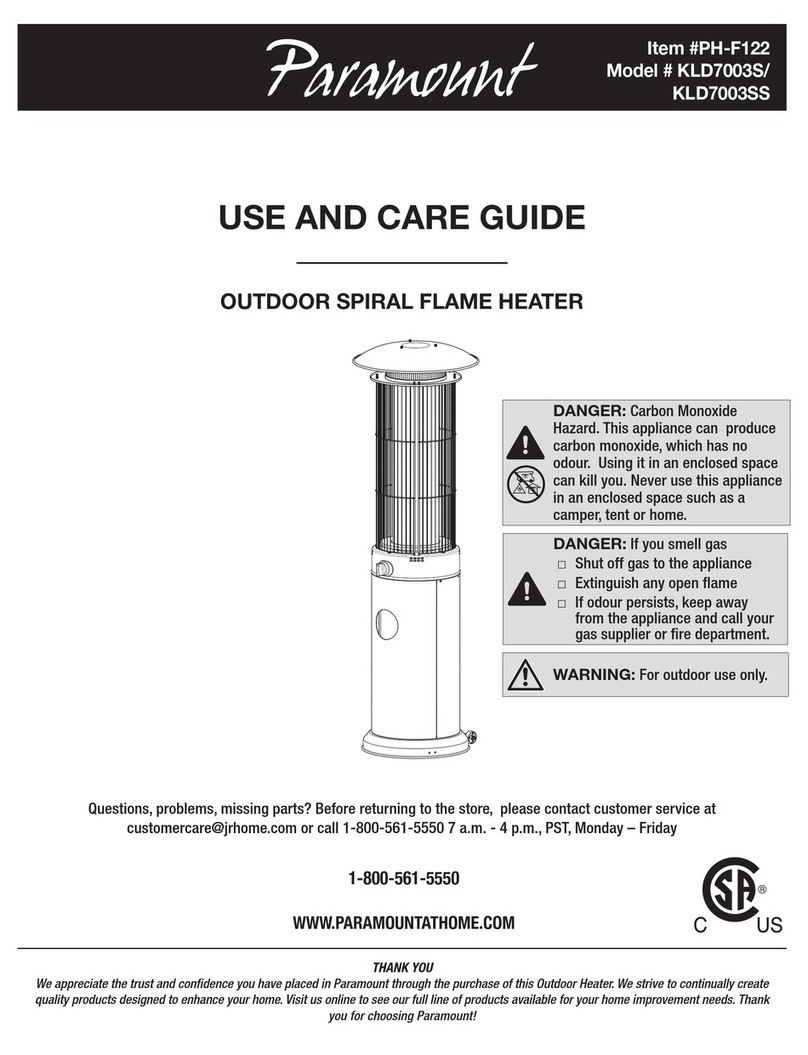
Paramount Fitness EDC Operating instructions

INSTALLATION &
OWNER’S MANUAL
8175 W. Buckeye Rd., Phoenix, AZ 85043
Toll Free: 1.800.621.5886 • Phone: 480.893.7607 • Fax: 480.753.3397
US and Foreign patents and patents pending
see www.1paramount.com/support/patent-numbers/
Paramount products are designed by Paramount in Phoenix, Arizona, United States of America
004-027-8703-00 R02 ECN_2208 PUB111821 ©2021 Hayward Industries, Inc.

2
Table Of Contents
Installing The Canister ................................................................................................. 6
Plumbing The Canister ................................................................................................ 7
Plumbing Before The Equipment Header Or Pump ............................................ 7
Plumbing After The Suction Side Header And Before The Pump..................... 8
Pressure Testing............................................................................................................ 9
Home Owner Instructions: Cleaning The Basket................................................10
Winterizing The EDC Canister ................................................................................11

3
PLEASE REVIEW THE OWNER’S MANUAL AND INSTALLATION GUIDE
IN ITS ENTIRETY AND HEED ALL SAFETY INFORMATION. Failure to follow
these instructions and warnings can result in SEVERE PERSONAL INJURY OR
DEATH.
DANGER DANGER indicates a hazardous situation which,
if not avoided, will result in death or serious injury.
WARNING WARNING indicates a hazardous situation which,
if not avoided, could result in death or serious injury.
CAUTION CAUTION indicates a hazardous situation which,
if not avoided, could result in minor or moderate
injury.
NOTICE NOTICE is used to address practices not related to
physical injury.
Signal Words and Symbols Used In This Manual
This Owner’s Manual and Installation Guide contains specific precautions and
symbols to identify safety-related information. You will find DANGER, CAUTION,
WARNING, NOTICE and SAFETY INSTRUCTIONS symbols which require
special attention. Please read them carefully and follow these precautions as
indicated! They will explain how to avoid hazards that may endanger you or
persons using or maintaining your pool or spa.

4
Do not remove this lid when this canister is
under pressure. Removing this lid with the
canister under pressure will result in serious
injury or death.
DANGER
Fully secure lid assembly to canister before
proceeding. Do not exceed 50 psi. when
pressure testing. Failure to do so will result
in serious injury or death.
DANGER
Fully secure lid assembly to canister before
applying pressure. If lid isn’t fully secured it will
result in serious injury or death.
DANGER
Do not stand over this lid when this canister is
under pressure. Doing so could result in serious
injury or death.
WARNING
This canister is under pressure during pressure
test. Removing the lid or standing over the lid
while the unit is under pressure could result in
serious injury or death.
WARNING
This debris canister should only be installed on
the suction side of the system. Failure to do so
could result in serious injury or death.
WARNING

5
3 Mounting Feet
2 ports for
plumbing in the
optional Clear
O3 ozone water
purifier or vacuum
gauge
The inlet port
is 2½"
schedule 40
pipe size on
the ID. The OD
accepts a 3"
coupler (spigot)
The outlet port
is 2½"
schedule 40
pipe size on
the ID. The OD
accepts a 3"
coupler (spigot)
Clear lid
& bayonet
assembly

6
LOCATING THE CANISTER FOR BELOW GRADE
INSTALLATION
The EDC canister can be installed below grade. The minimum hole footprint is
24" x 24". The hold depth varies for per your requirements. Backfill the hole after
plumbing; be sure to compact the soil around the canister to ensure stability.
2½" or 3" PIPE TO
SUCTION LINES
FROM POOL
SET AT HEADER PIPE LEVEL
2½"or 3" PIPE TO
SUCTION OF PUMP
DEPTH WILL VARY
INSTALLING THE EDC AT GRADE
Set the canister at the desired position on the pad. Then anchor with appropriate
hardware using the three mounting feet. Failure to anchor the canister puts
undue stress on glue joints when removing the lid. Over time this can result
in leaks. Also, anchoring the canister reduces vibration and aids in quieter
operation of the equipment.

7
PLUMBING THE EQUIPMENT SIDE CANISTER
WARNING This debris canister should only be installed
on the suction side of the system.
8" Minimum
Straight Pipe
Filter
All Suction Header
Pump
OPTION 1:
ALL SUCTION PIPES
GOING TO EDC
Plumb the suction header as you
normally would. From the suction
header plumb the suction line into
the inlet port of the EDC. There
must be 8" of straight pipe between
the pump and any fittings.
OPTION 2:
SINGLE SUCTION
ITEM ON EDC
Plumb a suction line from an outlet
fitting to the inlet port of the EDC.
From the bottom outlet of the EDC
go directly into the header with
other suction items. There must
be 8" of straight pipe between the
pump and any fittings.
8" Minimum
Straight Pipe
Filter
Isolated
Suction Port
Pump
Other Suction
Header Items

8
8" Minimum
Straight Pipe
Apply primer twice before gluing
pipe or fittings to EDC canister
Pump
Install 3 Way Valve
Ahead of the LeafVac O N LY
Suction From the
Skimmer, Main Drain
or Spa
NOTICE Always be sure to have a minimum of 8
inches of pipe between the suction inlet of
the pump and the first connection whether
it is an EDC or a plumbing manifold.
The EDC canister is made of a 30% glass filled Noryl material for strength.
This requires priming the sockets two times, before applying the PVC glue.
Fittings, unions and pipe are not included.

9
PRESSURE TESTING
Fully secure lid assembly to canister before
proceeding. Do not exceed 50 psi. when
pressure testing. Failure to do so will result
in serious injury or death.
DANGER
¼" NPT
Accepts ½" pipe or
3
/
4
" fitting
Optional Ports:
The EDC canister has 3 optional ports. Two of the optional ports are ¼" NPT
blind ports located approximately 18" from the base. The third optional port is
located on the bottom side of the EDC. It is sized to accept ½" pipe or a ¾"
fitting.
If pressure testing is required, you can use the system pressure gauge to
determine testing pressure or you may use one of the ¼" NPT blind ports of
the EDC canister. This requires the ¼" NPT port be drilled through. Use a 1/8"
drill bit being careful not to damage the threads. The bottom of the ¼" port has
a drill point for centering your drill bit. Use thread sealant (DO NOT use Teflon
tape) on the pressure gauge. If you use this port for pressure testing at startup
you can either plug the port or install a vacuum gauge for normal operation.
The ¼" NPT ports can be used for a pressure gauge during pressure testing
or a vacuum gauge during normal operation. Another use would be for a
suction side device such as the Paramount Clear03 ozone generator.
The single ½" pipe ¾" fitting port can also be used for suction side devices.

10
HOME OWNER INSTRUCTIONS:
CLEANING THE BASKET
Ring
Lid
Fine mesh bag
Debris
basket
NOTICE Make sure to turn off the pump.
To clean the basket you must remove the lid. Turn the two handles
counterclockwise one quarter turn. Set the lid aside making sure to keep the
o-ring clean.
NOTICE The lid cannot be removed from the ring.

11
When replacing the lid and ring make sure that the top of the EDC canister is
free from all dirt and debris and the o-ring on the lid is clean. Paramount does
not recommend using lube on the lid o-ring as it attracts dirt and debris. Some
lubricants can cause swelling and damage to the o-ring.
NOTE: An optional fine mesh bag is available for fine debris that may pass
through the standard basket. Use of the optional fine mesh bag will require more
frequent cleaning.
WINTERIZING THE EDC CANISTER
The EDC canister must be winterized in areas prone to freezing temperatures. To
winterize, remove the EDC canister lid and pump lid. Use a wet or dry vacuum to
remove all the water from the EDC. Replace the EDC lid and proceed with your
normal winterizing process. Consult your local pool professional for the best
winterizing method.
NOTICE
All water must be removed from the EDC canister
in areas that experienced freezing temperatures.
Failure to do so will cause damage to the canister
that will not be covered under warranty.
INSTALLING THE OPTIONAL FINE MESH BAG
The optional 600 micron bag is designed to filter dirt and debris that can clog
the pool pump.
The fine mesh bag will still allow DE to be fed through it for charging.
Replace the basket into the EDC and fully secure the lid to the EDC.
Remove debris
basket from
canister. Remove
handle by pushing
on one side to
release from
basket.
The mesh bag fits only
one way. Align the
small notch on mesh
bag ring with white
arrow on basket.
Make sure bag
is flush with the
basket and re-
attach the handle.

12
Paramount Part# Description
004-152-4516-00 EDC Canister Complete
1005-152-2205-00 Lid Assembly includes, clear lid, ring, o-ring
2005-152-2206-00 O-Ring
3005-152-2207-00 Basket Assembly
4005-152-2208-00 Canister Replacement body only
5004-152-4517-00 Optional Fine Mesh Bag
1
2
3
4
5

GUIDE D’INSTALLATION
ET MANUEL DU
PROPRIÉTAIRE
8175 W. Buckeye Rd., Phoenix, AZ 85043
Toll Free: 1.800.621.5886 • Phone: 480.893.7607 • Fax: 480.753.3397
US and Foreign patents and patents pending
see www.1paramount.com/support/patent-numbers/
Paramount les produits sont conçus par Paramount in Phoenix, Arizona, Les états-unis
004-027-8703-00 R02 ECN_2208 PUB111821 ©2021 Hayward Industries, Inc.

14
Table des matières
Installer La Boîte Filtrante .........................................................................................18
Bien Fixer L’unité Au Socle ......................................................................................18
Tuyauterie De La Boîte Filtrante...............................................................................19
Tuyauterie Avant Le Port De L’appareil Ou La Pompe ......................................19
Tuyauterie Après L’extrémité Aspirate Et Avant La Pompe................................20
Essai De Pression.......................................................................................................21
Consignes À L’intention Du Propriétaire : Nettoyage Du Panier .....................22
Hivérisation De La Boîte Filtrante EDC.................................................................23

15
VEUILLEZ BIEN LIRE L’ENSEMBLE DU MANUEL DU PROPRIÉTAIRE
ET DU GUIDE D’INSTALLATION, ET SUIVRE À LA LETTRE TOUTES LES
CONSIGNES DE SÉCURITÉ, AU RISQUE DE VOUS EXPOSER À DES
RISQUES DE LÉSION PHYSIQUES GRAVES OU MORTELLES.
DANGER Le symbole DANGER indique la présence d’un
risque significatif de lésions physiques ou mortelles.
AVERTISSEMENT
Le symbole AVERTISSEMENT indique la présence
d’un risque pouvant entraîner des lésions physiques
ou mortelles
PRÉCAUTION Le symbole PRÉCAUTION indique la présence
d’un risque pouvant entraîner des lésions légères à
modérées
AVIS Le symbole AVIS correspond à des pratiques non
liées aux lésions physiques.
MOTS ET SYMBOLES UTILISÉS DANS LE PRÉSENT GUIDE
La présent manuel du propriétaire et guide d’installation contient des
précautions et des symboles spécifiques visant à vous transmettre des
renseignements sur la sécurité. Les symboles et les mots DANGER,
PRÉCAUTION, AVERTISSEMENT, et RENSEIGNEMENT DE SÉCURITÉ
doivent faire l’objet d’une attention particulière. Veuillez les lire attentivement et
prendre consciencieusement toutes les précautions indiquées! Elles expliquent
comment éviter les risques qui pourraient mettre en danger toutes les personnes
qui utilisent ou entretiennent votre piscine ou spa.

16
AVERTISSEMENT
La boîte filtrante est sous pression pendant
l’essai de pression. Enlever le couvercle ou se
tenir au-dessus du couvercle lorsque l’unité
est sous pression entraîne un risque de lésion
physique grave ou mortelle.
AVERTISSEMENT
Cette boîte filtrante à débris doit être installée
à l’extrémité aspirante du système, au risque
de courir un risque de lésion physique grave ou
mortelle.
Ne pas se tenir au-dessus du couvercle lorsque
la boîte filtrante est sous pression, au risque de
vous exposer à un risque de lésion physique
grave ou mortelle.
DANGER
Ne pas dépasser 50 psi. pendant les essai de
pression, au risque de subir des lésions graves
ou mortelles
DANGER
Ne pas enlever ce couvercle lorsque la boîte
filtrante est sous pression, au risque de vous
exposer à un risque de lésion physique grave ou
mortelle.
DANGER

17
3 pieds de fixation
Ports pour la
tuyauterie du
purificateur d’eau
(facultatif) Clear O3
ozone, ou le tuyau
d’aspiration.
L’orifice
d’admission
est un tube de
2½" de DI et
de calibre 40.
Le DE peut
être relié à un
coupleur (mâle)
de 3".
Le port de
sortie est un
tube de 2½" de
DI et de calibre
40. Le DE peut
être relié à un
coupeur (mâle)
de 3".
Couvercle
transparent
et ensemble
de raccord à
baïonnette

18
INSTALLER LA BOÎTE FILTRANTE SOUS LE
NIVEAU DU SOL
La boîte filtrante peut être installée sous le niveau du sol. Creuser un trou d’au
moins 24” x 24”/61 cm x 61 cm, sans restriction de profondeur. Remblayer le
trou après y avoir installé la tuyauterie, en veillant à bien tasser le sol autour de la
boîte filtrante afin d’en assurer la stabilité.
TUYAU DE 2½" À /3"
DE LA PISCINE AUX CONDUITES
D’ASPIRATION INSTALLÉ AU NIVEAU
DE LA CONDUITE COLLECTRICE
CONDUITE DE 2½" À 3" VERS
L’EXTRÉMITÉ ASPIRANTE DE LA
SOCLE
PROFONDEUR VARIABLE
AU MOINS 24"
BIEN FIXER L’UNITÉ AU SOCLE
Fixer l’unité au coussinet au moyen des trois pattes d’assemblage. Placer le
réservoir sur le coussinet, et maintenir en place. Omettre cette étape exerce
une pression excessive sur les joints de colle au moment de retirer le couvercle,
ce qui avec le temps, risque d’entraîner des fuites. De plus, maintenir en place
le réservoir réduit la vibration et permet un fonctionnement plus silencieux de
l’équipement.
AU MOINS 24"
AU MOINS 24"

19
TUYAUTERIE DE LA BOÎTE FILTRANTE
AVERTISSEMENT
Cette boîte de filtration des débris ne doit
être installée qu’à l’extrémité d’aspiration du
système.
Filter
Tous aspiration Header
Pump
Tuyau d’u
Moins 8 po.
OPTION 1:
TOUTES LES
CONDUITES
D’ASPIRATION VERS
L’EDC
Plombez la tête de succion comme
vous le feriez d’habitude. À partir
de la tête de succion, plombez la
conduite d’aspiration dans le port
d’admission de l’EDC. Il devrait
y avoir 20 cm de conduite droite
entre la pompe et tout raccord.
OPTION 2:
SUCCION SIMPLE
ITEM VERS L’EDC
Plombez la conduite d’aspiration de
l’item (dont vous voulez recueillir les
débris) au port d’admission de l’EDC.
Du bas de la prise de l’EDC, allez
directement dans la tête avec les
autres items de succion. Il devrait y
avoir 20 cm de conduite droite entre
la pompe et tout raccord.
Filter
l'orifice d'aspiration isolé
Pump
Autre aspiration
header article
Tuyau d’u
Moins 8 po.

20
Pump
Installez la valve à 3 voies
en amont SEULEMENT du LeafVac
La succion du
récupérateur, du drain
principal et du spa
Tuyau d’u
Moins 8 po.
Veiller à toujours laisser au moins 8 po./20
cm de conduite entre l’entrée aspirante
de la pompe et le premier raccord, qu’il
s’agisse d’un EDC ou d’une manivelle de plomberie.
La boîte filtrante EDC est composée de Noryl renforcé à 30% en verre
pour en rehausser la force. C’est pourquoi il est nécessaire d’apprêter
les bouts deux fois avant d’appliquer la colle PVC. Fixations, raccords et
conduites non inclus.
AVIS
Table of contents
Languages:
Other Paramount Fitness Heater manuals
Paramount Fitness
Paramount Fitness HCH500 User manual

Paramount Fitness
Paramount Fitness GZBW151A User manual

Paramount Fitness
Paramount Fitness KLD7003S User manual

Paramount Fitness
Paramount Fitness PH-F-121-BK MO User manual

Paramount Fitness
Paramount Fitness PH05-S Parts list manual

Paramount Fitness
Paramount Fitness Stealth PH-F-126 User manual