Paramount Fitness Ultra UV2 User manual

Paramount
8175 W. Buckeye Rd.,
Phoenix, AZ 85043
Phone: 1-800-621-5886
www.1Paramount.com
Ultra UV2
Ultimate UV Water Sanitizer
Owner's Manual
Contents
Safety Instructions..................1
Introduction............................3
Installation.............................4
System Start-Up....................10
Maintenance.........................12
FAQs.....................................16
Troubleshooting....................17
Replacement Parts................21
004-027-9000-00 REV06
ECN_2365 PUB032423
Plug In 120V Models Hard Wired 120/230V Models
1 Lamp 004-422-2021-00 004-422-2025-00
2 Lamps 004-422-2022-00 004-422-2026-00
3 Lamps 004-422-2023-00 004-422-2027-00
Pool, Spa & Pond
Water Sanitizer 4BJ1
EPA Est. No.
101936-SGP-1
USE ONLY PARAMOUNT GENUINE REPLACEMENT PARTS

Important Safety Instructions
READ AND FOLLOW ALL INSTRUCTIONS
WARNING - When using this electrical equipment, basic safety precautions should always
be followed, including the following:
• Follow all applicable electrical codes.
• Turn off power at main source before making any electrical connections or servicing the
unit.
• To reduce risk of electric shock, injury or death disconnect unit from power supply
• Follow the instructions or risk of serious injury or death could occur!
• To reduce risk of injury, do not permit children to use this product unless they are
closely supervised at all times.
• Risk of electric shock. Install at least 5 feet (1.5m) from inside wall of pool, hot tub or
spa using nonmetallic plumbing.
• This product shall only be connected to a power supply receptacle protected by a
ground fault circuit interrupter.
WARNING - UV EXPOSURE & PROTECTION: UV-A and UV-B radiation can have adverse
short and long term effects on the eyes and skin. Never look directly at a UV lamp that is
connected to a power source. Avoid UV skin exposure at all times.
DANGER - RISK OF INJURY: (a) Replace damaged cord immediately. (b) Do not bury cord.
(c) Connect to a grounded, grounding type receptacle only.
PLEASE REVIEW THE OWNER’S MANUAL IN ITS ENTIRETY AND HEED ALL SAFETY INFOR-
MATION. FAILURE TO FOLLOW THESE INSTRUCTIONS AND WARNINGS CAN RESULT IN
DEATH OR SERIOUS INJURY.
SAVE THESE INSTRUCTIONS
This Owner’s Manual contains specific precautions and symbols to identify safety related infor-
mation as described below. Please read them carefully and follow these precautions as indicated!
DANGER - Indicates a hazardous situation which, if not avoided, will result in death or
serious injury.
WARNING - Indicates a hazardous situation which, if not avoided, could result in death
or serious injury.
CAUTION - Indicates a hazardous situation which, if not avoided, could result in minor
or moderate injury.
NOTICE - Is used to address practices not related to physical injury.
!
!
!
!
!
1
USE ONLY PARAMOUNT GENUINE REPLACEMENT PARTS

Table of Contents
Important Safety Instructions..................................................................................................1
Introduction..............................................................................................................................3
General Product Information...............................................................................................3
Ultra UV2System Sizing.....................................................................................................3
Installation..............................................................................................................................4
Locating The Ultra UV2Unit................................................................................................4
Mounting the UV Unit on a Solid Base.................................................................................5
Installing Inlet/Outlet Unions...............................................................................................5
Plumbing The Ultra UV2Unit...............................................................................................5
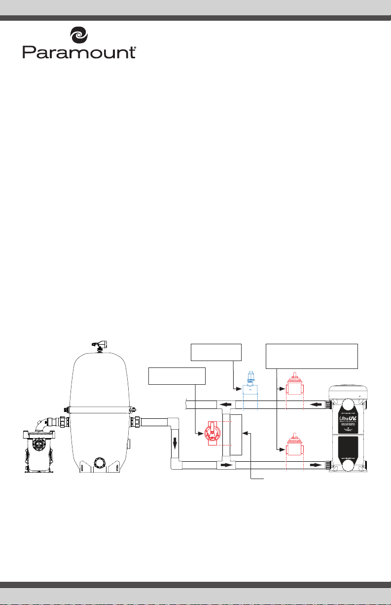
Typical Plumbing With and Without Bypass...................................................................6
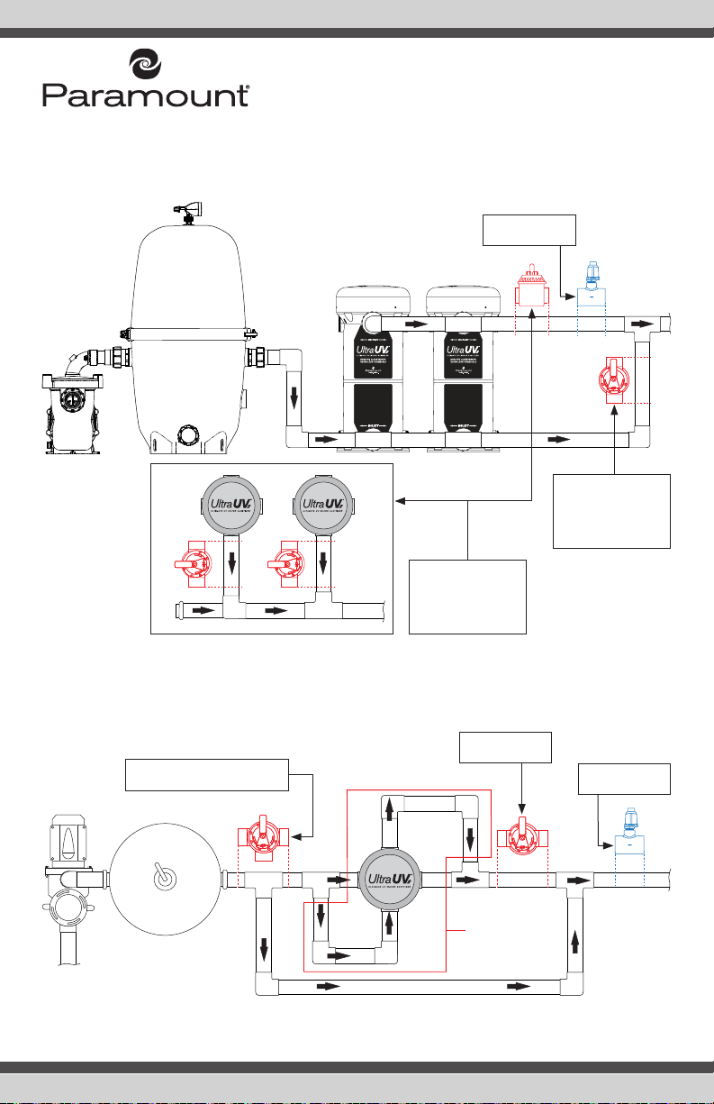
Parallel Plumbing With and Without Bypass..................................................................7
Mutiple Port Plumbing for 3 Lamp Units With and Without Bypass.................................7
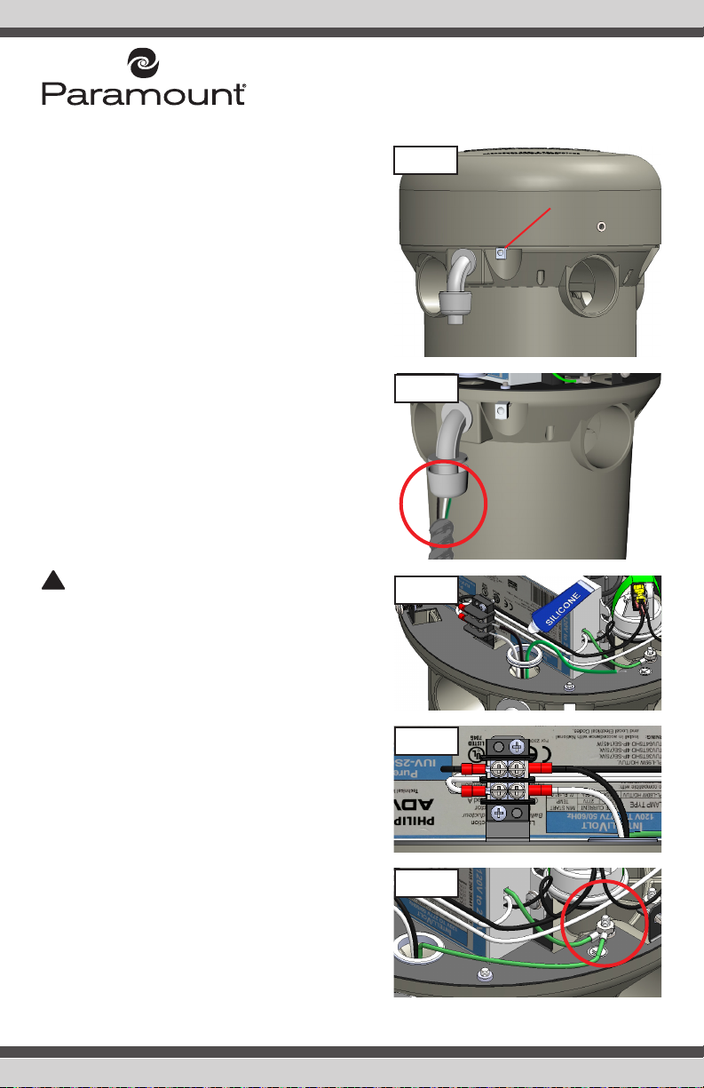
Electrical Wiring.................................................................................................................8
Plug In 120V 50/60Hz Ultra UV2Units.........................................................................8
Hard Wired 120/230V 50/60Hz Ultra UV2Units............................................................9
Electrical Bonding.......................................................................................................9
System Start-Up...................................................................................................................10
Pressure Switch...............................................................................................................10
Water Chemical Balance..................................................................................................10
Normal Operation.............................................................................................................11
Winterize/Service Operation..............................................................................................11
Maintenance.........................................................................................................................12
Winterization of Your Ultra UV2Unit...................................................................................12
Quartz Tube Maintenance.................................................................................................13
Scheduled UV Lamp(s) Replacement.................................................................................15
FAQs.....................................................................................................................................16
Troubleshooting....................................................................................................................17
Identifying and Correcting System Problems......................................................................17
Specification Notice.........................................................................................................19
Limited Warranty..............................................................................................................19
Head Loss Curves............................................................................................................20
Replacement Parts................................................................................................................21
USE ONLY PARAMOUNT GENUINE REPLACEMENT PARTS
22

Introduction
WARNING - The Ultra UV2unit is designed for use in swimming pools, spas, fountains, water
features, waterfalls, fish ponds and the like. IT IS NOT DESIGNED FOR USE IN POTABLE (DRINK-
ING) WATER INSTALLATIONS. Use of this product in applications other than those indicated
above will void your warranty and could be harmful to your health or the health of others.
General Product Information
Water circulates through the Ultra UV2chamber and around the quartz tube where the UV-C lamp(s)
(1 to 3 lamps depending on the model) are housed. The UV-C lamp emits a light wave spectrum
(253.7 nm wavelength) to immediately inactivate 99.9% of micro-organisms such as Crypto, Giar-
dia, other single celled waterborne microorganisms and algae which are resistant to chlorine. This
provides a cleaner, clearer swimming environment with zero harmful by-products and dramatically
reduces the amount of chlorine needed to maintain an adequate level of residual sanitizer. The Ultra
UV2 unit has been sized to produce these important UV rays in the same intensity as is required for
Class A potable drinking water, which is 30,000 micro watts/cm2 (30 mJ). Refer to the table on page
4 to determine the Ultra UV2 Part Number needed for your application. Please note the minimum
and maximum flow rates for each Ultra UV2 lamp configuration.
CAUTION - Do not use this unit for potable (drinking) water sanitation.
Ultra UV2 System Sizing
In order to ensure that your Ultra UV2 unit functions with the proper water exposure time to achieve
the desired water sanitation, it is important to provide the proper water flow rate through the Ultra
UV2 unit. If water passes through the unit too quickly, the microorganism’s exposure time to the UV
lamp(s) produced rays will not be sufficient to obtain the desired rate of sanitation. Please note that
the minimum posted flow rate must be met or exceeded to ensure proper system perfor-
mance. The water flow rate through the UV unit is governed by the piping of your water vessel and
the size and output of your circulation pump. Consideration to the application for the UV unit must
be determined. Fish ponds, as an example, have different requirements than swimming pools, spas,
water features, fountains, or waterfalls, as noted elsewhere in this manual.
Swimming pools and similar water vessels are simple to calculate. See table on page 4. NOTE: All
capacities are nominal. Multiple Ultra UV2 units installed in parallel can be used for flow rates be-
yond those specified herein (see page 7).
!
!
3
USE ONLY PARAMOUNT GENUINE REPLACEMENT PARTS

Pool, Spa, Fountain, Water Feature And Water Fall Sizing Chart
Part Number
Minimum
Flow Rate
GPM /
(m3/hr)
Maximum
Flow Rate
GPM /
(m3/hr)
Max. Pool
Volume 12 Hr.
Turnover
Gallons /
(m3/hr)
Max. Pool
Volume 8 Hr.
Turnover
Gallons /
(m3/hr)
Minimum
Operating
Pressure
psi / bar
Maximum
Operating
Pressure
psi / bar
004-422-2025-00
(Hard Wired 120V/230V 1 Lamp)
004-422-2021-00
(Plug In 120V 1 Lamp)
10 / 2.27 46 / 10.4 33120 /
125.4
22080 /
83.6 5 / 0.345 50 / 3.45
004-422-2026-00
(Hard Wired 120V/230V 2 Lamps)
004-422-2022-00
(Plug In 120V 2 Lamps)
20 / 4.54 80 / 18.2 57600 /
218.0
38400 /
145.4 5 / 0.345 50 / 3.45
004-422-2027-00
(Hard Wired 120V/230V 3 Lamps)
004-422-2023-00
(Plug In 120V 3 Lamps)
*30 /
6.81
*130 /
*29.5
93600 /
354.3
62400 /
236.2 5 / 0.345 50 / 3.45
*Header size should be 2½" or 3" and split to two 2" pipe headers at the inlet and outlet connections.
Installation
NOTICE - The first step in starting your installation is to inspect the Ultra UV2 unit for damage,
paying close attention to the quartz tube.
Locating the Ultra UV2 Unit
Your unit can be installed indoors or outdoors. When consider-
ing the location for your Ultra UV2 unit, keep it close to your
power source. Check the silver product label for the voltage of
the unit. The Ultra UV2 unit will need to be powered from either
a 120V/15A/50/60Hz or 230 V/15A/50/60Hz electrical circuit
(which MUST match the unit power requirement noted on the
silver product label on the Ultra UV2 unit). DO NOT CONNECT
TO ELECTRICAL POWER NOT SPECIFIED FOR YOUR UNIT.
Plug in units must be installed on a GFCI outlet. The GFCI must
be outdoor rated if installed outdoors. Hard Wired Ultra UV2
units can be wired for 120V or 230V.
WARNING - DO NOT CUT OFF corded plug from the
120V Ultra UV2 units and hard wire it. This does not meet
the U.L. installation method and voids the U.L. listing.
!
Power Requirements
(Silver Product Label)
USE ONLY PARAMOUNT GENUINE REPLACEMENT PARTS
4
USE ONLY PARAMOUNT GENUINE REPLACEMENT PARTS

Mounting the UV Unit on a Solid Base
Before you make the permanent plumbing connections, be sure the Ultra UV2 unit is on a solid level
base with aligned plumbing connections. Make sure there is ample space above the unit for lamp
replacement. After making your plumbing connections, anchor the unit to the base using the four
¼” mounting holes. FAILURE TO PROPERLY SECURE THE UNIT MAY CAUSE NOISE OR VIBRATION.
Installing Inlet/Outlet Unions
The Ultra UV2 unit comes with female socket glue-in inlets and outlet openings. ABS to PVC mul-
tipurpose glue and appropriate primer must be used to glue fittings into the Ultra UV2 body. The 4
outlets (top) and 4 inlets (bottom) provide the most versatile piping alternatives for the installer. 1 and
2 lamp units include two unions for plumbing inlet & outlet pipes. 3 lamp units include four unions
for plumbing inlet and outlet pipes as shown on page 7.
NOTE: To install the union onto the Ultra UV2 unit, glue and insert the union spigot end into the inlet
and outlet opening selected. Then, using the six plugs provided, glue the plugs into the remaining
unused plumbing openings. Hand tightening the union nuts until snug is sufficient. DO NOT OVER
TIGHTEN. Over tightening may break the molded plastic parts of the union.
NOTICE - 24 hour cure time is required before pressure can be applied to the Ultra UV2 unit.
Plumbing the Ultra UV2 Unit
All plumbing methods are illustrated with and without the bypass option. Your Ultra UV2 unit will need
to be plumbed into the circulation system. The Ultra UV2 unit must be installed directly after the filter.
Installing a bypass is not recommended (see page 6).
NOTICE - An improperly used bypass installation may not meet the minimum required flow
rate and could potentially damage the Ultra UV2 unit.
NOTICE - Do not plumb the Ultra UV2 with a bypass unless absolutely needed. Failure to fol-
low the instructions can result in damage to the Ultra UV2 that is not covered by the warranty.
DANGER - Turn off the power at the main source before disconnecting or connecting the
Ultra UV2.
NOTICE - Using the supplied unions is strongly recommended.
Gluing Piping to the UV Unit
Two Inlet/Outlet unions are supplied on 1 & 2 lamp units and 4 unions are supplied on 3 lamp units.
Your PVC supply piping should be glued into the union tail pieces using an appropriate primer and
ABS to PVC cement. Inlet piping should be supported and should not rest solely upon the unions,
to avoid stressing or breaking the unions. Allow the glue to set following the glue manufacturers
recommendations before pressure testing. A minimum of 24 hours is recommended. Maximum test
pressure for the Ultra UV2 is 50 PSI / 3.45 BAR as noted on the silver label on the unit. If local codes
require the pressure test to be higher than the max operating pressure on the silver label, use the
!
5
USE ONLY PARAMOUNT GENUINE REPLACEMENT PARTS

bypass (if the unit is plumbed with a bypass) to ensure that the Ultra UV2 is at or below the max
operating pressure.
A. Plumbing the Ultra UV2 Unit with Optional Bypass Valve
Installing a bypass is not recommended and should only be considered:
1. To allow for removal of the UV unit for winterization, servicing, repairs, or replacement,
while still allowing water to flow through the system. Before bypassing the Ultra UV2 for
removal, turn off all pumps and allow the pool system’s pressure to drop to zero.
2. If system pressure testing above 50 psi is required (max Ultra UV2 pressure is 50 psi /
3.45 bar).
B. Installing Optional Flow Switch if the Top of the Unit is Below Water Level
The pressure switch can always be on if the Ultra UV2 unit is plumbed below water level. To
prevent damage to the unit and its surroundings, an optional flow switch must be installed. If
the Ultra UV2 unit is plumbed on a bypass, the optional 2 inch Flow Switch (part #004-402-
0010-00 for 230V or part #004-421-3824-00 for 120V), must be on the outlet side of the
Ultra UV2 unit and plumbed after the two way valve and before the tee into the return line.
Please refer to the instructions supplied with the flow switch for plumbing and wiring.
Typical Plumbing With and Without Bypass
The inlet(s) is at the bottom of the unit and the outlet(s) at the top. The maximum operating pressure
for the Ultra UV2 is 50 PSI / 3.45 BAR. The minimum operating pressure is 5 PSI / .345 BAR. Please
refer to the silver label on the unit for maximum operating pressure.
Filter
Pump
To Heater
or Pool
A. Optional Bypass
fully closed
B. Optional Flow
Switch
A. Optional Bypass Valves fully
open into Inlet Port and from
the Outlet Port
This pipe does not exist if bypass
valve is not installed.
USE ONLY PARAMOUNT GENUINE REPLACEMENT PARTS
6

Parallel Plumbing With and Without Bypass
Plumbing Ultra UV2 units in parallel for large bodies of water with high flow rates.
Multiple Port Plumbing for 3 Lamp Units With and Without Bypass
Ultra UV2 3 lamp units require 2 inlets and 2 outlets be plumbed.
To Heater
or Pool
Filter
Pump
Top
View
A. Optional Bypass
Valves fully open
into Inlet Port and
from the Outlet
Port
A. Optional bypass
fully closed. This
pipe does not exist
if bypass valve is
not installed
B. Optional Flow
Switch
To Heater
or Pool
2" Plumbing
(2½" or 3" for all
other plumbing)
Pump
Filter
In Out
Out
In
To Heater
or Pool
A. Optional Bypass Valves fully
closed in normal operation. B. Optional Flow
Switch
A. Outlet fully
open
7
USE ONLY PARAMOUNT GENUINE REPLACEMENT PARTS

Electrical Wiring
WARNING - Grounding. This product must be grounded. If it should malfunction or break
down, grounding provides a path of least resistance for electrical current to reduce the risk
of electric shock. Plug in models are equipped with a cord having an equipment-grounding
conductor and a grounding plug. The plug must be plugged into an appropriate outlet that is
properly installed and grounded in accordance with all local codes and ordinances.
DANGER - Improper connection of the equipment-grounding conductor can result in a risk
of electrocution. Check with a qualified electrician or service personnel if you are in doubt as to
whether the outlet is properly grounded. Do not modify the plug provided with the product - if
it will not fit the outlet, have a proper outlet installed by a qualified electrician. Do not use any
type of adapter with the product.
DANGER - Ground Fault Circuit Interrupter Protection. To comply with the national electri-
cal code (NFPA 70) and to provide additional protection from the risk of electric shock, this unit
should only be connected to a receptacle that is protected by a ground circuit interrupter (GFCI).
The electrical power rating for your Ultra UV2 unit is shown on the silver label located on the outside
of the unit (shown in the image on page 4). Make sure the supplied power meets the electrical re-
quirements. Connecting any power than that listed on the rating label will damage the unit and will
VOID your limited warranty.
Plug In 120V 50/60Hz Ultra UV2 Units
1. A properly rated ground fault circuit interrupter must be installed in the electrical outlet serving
the Ultra UV2. Check your local and national electrical codes.
2. Connect the included 3-plug grounded NEMA plug to an outlet protected by a ground fault
circuit interrupter.
3. Connect the electrical bonding per instructions shown on the following page.
WARNING - Do not cut the plug off the electrical cord and connect it directly to a 120V
power source. If this is done your warranty is voided and the U.L. listing is invalidated.
WARNING - Should the electrical cord become frayed or damaged in the future, unplug it
from the power receptacle and replace it immediately.
!
!
!
!
!
USE ONLY PARAMOUNT GENUINE REPLACEMENT PARTS
8

Hard Wired 120/230V 50/60Hz Ultra UV2 Units
NOTICE - Have this work done by a licensed
electrical technician.
1. Install the conduit into the seal-tight connector.
2. Lift the grommet from the mounting plate and
feed the black, white, and green wires (Fig. 2).
Use the supplied tube of silicone and cover the
wires at the junction of the conduit connector
(Fig. 3). Reinstall the grommet to the mounting
plate.
3. Attach one power leg (most likely black) to the
upper right position of the terminal block. Attach
one power/neutral leg (most likely white) to the
lower right position of the terminal block (Fig. 4).
NOTE: The terminal block is sized to accept a
spade terminal for 18-22AWG wire.
4. Cut the ground wire to length and attach an 18-
22 AWG ring terminal. Remove the nut from the
left ground post. Place the ring terminal over the
ground post. Reattach the nut. See Fig. 5.
WARNING - Failure to silicone the wires in the
connector could result in water from a leak in the
unit leaking down the conduit and causing non-
warranted damage to other components.
Electrical Bonding
Locate the bonding lug next to the power cable (Fig.
1). To reduce the risk of electric shock, this terminal
must be connected to the bonding lug in the electrical
supply service panel with a continuous copper wire
equivalent in size to the circuit conductors supplying
this equipment. To reduce the risk of electric shock,
connect the local common bond grid in the area of the
pool or spa to this terminal with an insulated or bare
copper conductor per national and local codes. The
electrical installation is now complete.
!
Bonding Lug
Fig. 1
Fig. 2
Fig. 3
Fig. 4
Fig. 5
9
USE ONLY PARAMOUNT GENUINE REPLACEMENT PARTS

System Start-Up
NOTICE - Do not connect the pressure switch until the pool is operational!
Pressure Switch
The Ultra UV2 unit is equipped with pressure a switch that does not allow the UV lamp(s) inside the
unit to light unless there is at least 2 PSI (0.137 BAR) inside the Ultra UV2 reactor chamber. This will
ensure that the lamp(s) will illuminate when the Ultra UV2 unit has water flowing through the reactor.
Connecting Pressure Switch
Disconnect power to the Ultra UV2 unit. Remove the
cover (Fig. 6) and locate the pressure switch and the
loose lead with the female spade connector (Fig. 7).
Connect the female spade connector to the male top
spade connector on the pressure switch (Fig. 8). Re-
place the cover and restore power to the unit. Turn on
the pump and when the flow switch is activated, the
unit should be on and the lamps illuminated. Look at
the “Glow Ring” in the center of the unit to check that
all lamps are lit. If the lamps are not lit, please check
the following:
1. Adjust the system valves to ensure adequate flow
through the Ultra UV2 unit.
2. Increase the pump speed to produce enough
pressure to energize the Ultra UV2 unit.
3. Refer to the troubleshooting section of this man-
ual (page 17).
NOTICE - The filter gauge DOES NOT indicate
the pressure in the UV unit.
WARNING - Do not look directly at the lamps.
Serious injury will occur.
Water Chemical Balance
If you have installed your Ultra UV2 unit on any water
vessel other than fish ponds or ponds with live plants,
it is important that you check and adjust the chemical
balance of the water. The Ultra UV2 unit dramatically
reduces the need for chemical sanitizers, but a mini-
mum sanitizer residual must be maintained.
!
Fig. 6
Fig. 8
Fig. 7
USE ONLY PARAMOUNT GENUINE REPLACEMENT PARTS
10

Normal Operation
Configuration for Ultra UV2 units installed with bypass. During normal operation, the inlet valve #2
and outlet valve #3 should be completely open and the bypass valve #1 should be completely closed.
This instruction applies to all systems with a single speed or with a variable speed pump. This type of
damage is not covered under the factory warranty. Any partial opening of the bypass valve can drop
the flow rate below the required minimum and cause damage to the Ultra UV2 unit.
Winterize / Service Operation
Configuration for Ultra UV2 units installed with bypass. Bypass operation is used for winterization or
servicing the Ultra UV2 unit. The bypass valve #1 should be fully open and the inlet valve #2 and the
outlet valve #3 should be completely closed.
Filter
To Heater
or Pool
Pump
Bypass Valve #1
CLOSED
Outlet Valve #3 OPEN
Inlet Valve #2 OPEN
Filter
To Heater
or Pool
Pump
Outlet Valve #3 CLOSED
Bypass Valve #1
OPEN
Inlet Valve #2 CLOSED
11
USE ONLY PARAMOUNT GENUINE REPLACEMENT PARTS

Maintenance
Winterization of Your Ultra UV2 Unit
If you are in a sub freezing climate, you must winter-
ize the Ultra UV2 using either option #1 or #2. Failure
to do so will cause damage to the unit, which is not
covered under the warranty.
Option #1 - Removing the unit for the winter: Turn off
the power to the unit. Disconnect the unions on the
plumbing to ensure that the unit is completely drained.
Now, with the power off, disconnect the unit from its
power source and place the drained unit in a safe
place that has a sustained temperature above freez-
ing. Reinstall after the temperatures are considerably
above freezing.
Option #2 - Leaving the unit in place for the winter:
Turn off the power to the unit. Disconnect the unions
on the plumbing to ensure that the unit is completely
drained. There is a cup in the bottom of your unit that
the quartz tube nests in. This cup (shown on the right)
does not drain completely. To remove the water from
this cup you must first remove the lamp array and
quartz tube. Turn the unit on its side with the unions
facing down until all of the water has drained. Recon-
nect the unit, the quartz tube, lamps, and cover. You
may store the lamps and quartz tube in a safe place.
Unions
Cup
USE ONLY PARAMOUNT GENUINE REPLACEMENT PARTS
12

Quartz Tube Maintenance
NOTICE - The quartz tube requires cleaning every 6
months to ensure optimum performance.
1. Turn off all power to the Ultra UV2 unit and all other
pool equipment. Unplug the unit from its power recep-
tacle or turn OFF the circuit breaker that is the Ultra
UV2’s power source. Allow at least 15 minutes for the
lamp(s) in the unit to cool before proceeding to step 2.
DANGER - Never remove the electrical enclosure
cover without first disconnecting the power (power
source) for the Ultra UV2 unit. Never remove the Ultra
UV2 unit’s cover without turning off the pump.
2. Remove the three screws that secure the plastic cover
then remove it.
WARNING - Before removing lamps, you must wear
protective rubber gloves and safety eyewear. Do not
handle a hot lamp or serious burns will occur.
NOTICE - Do not touch the glass part of the lamp as
body oils will create hot spots & greatly shorten lamp
life.
3. Disconnect all lamps by pressing the release tabs on
connectors and gently pulling apart (Fig. 9).
4. Remove the spring clip (Fig. 10). Carefully lift the old
lamp assembly, including lamp holder, from the quartz
tube (Fig. 11). Do not pull excessively on the lamp
wires. Set aside the lamp assembly in a safe area to
avoid breaking or chipping.
5. Turning counter-clockwise, unscrew and remove the
round aluminum sealing nut (Fig. 12).
6. Carefully lift the aluminum compression washer from
the top of the quartz tube making sure not to lose the
black gasket that cushions the edge of the quartz tube
(Fig. 13).
7. Grip quartz tube with both thumbs inside and pull up
(Fig. 14). Once the O-ring breaks free, the quartz tube
should lift out easily.
NOTICE - The quartz tube is fragile, be sure to han-
dle it with proper care and do not set it down on a hard
surface. Do not use abrasive cleaners or pads.
!
!
Fig. 9
Fig. 10
Fig. 11
Fig. 12
Fig. 13
13
USE ONLY PARAMOUNT GENUINE REPLACEMENT PARTS

8. Using protective rubber gloves and eye wear. To clean
the outside of the quartz tube, use shower/tub cleaner,
CLR or equivalent, or a solution of white vinegar and
water. Remove the O-ring from the quartz tube. If the
inside of the quartz tube is moist or needs cleaning,
use the same cleaning method. The quartz tube must
be completely dried and clear of residue especially
near the surface where the O-ring rests before reas-
sembly.
9. Inspect the quartz tube carefully for any cracks or
chips and replace the quartz tube if any are found.
NOTICE - Do not use any other O-ring at any time for
sealing the quartz tube. Doing so can result in a leak
and possible damage to your UV unit. The O-ring must
be replaced after cleaning the quartz tube. See page
21 for part number.
10. All components must be completely dry and clean, es-
pecially near the surface where the O-ring rests. Never
use any type of lube or sealing agent. To reinstall the
quartz tube, place a new O-ring 2 inches from the top
of the outside of the quartz tube (Fig. 15). Gently lower
the quartz tube into the unit until the O-ring makes
contact with the top of the black threaded sealing
sleeve. Note: Use a Paramount O-ring seal only.
11. Place the aluminum compression washer and gasket
on the quartz tube (Fig. 16). Press down on the alumi-
num compression washer with an even steady pres-
sure. This will roll the O-ring into the area between
the inside of the black threaded sleeve and the quartz
tube. Lift aluminum washer and check to make sure
it is seated evenly around the circumference of the
quartz tube (Fig. 17). Replace aluminum washer then
screw on the quartz sealing aluminum nut to hand
tight plus ½ turn.
12. Turn power on to the Ultra UV2 unit. Turn pump on
to check for leaks. Confirm that there are no leaks,
then turn off pump and power off to the unit. Reinstall
lamps, spring clip and connect to ballast(s). Reattach
cover. Turn power on to unit and turn pump on.
CAUTION - Do not stand over the unit when it is
under pressure or when the pump is on.
!
Fig. 14
2"
Fig. 15
Fig. 16
Fig. 17
USE ONLY PARAMOUNT GENUINE REPLACEMENT PARTS
14

!
!
Scheduled Uv Lamp(s) Replacement
The UV lamp(s) have a useful life of approximately
2½ years and should be replaced at that time. Even
though the lamp(s) may be glowing after 2½ years of
operation, they have reached the end of their useful
life.
1. Turn off all power to the Ultra UV2 unit and all
other pool equipment. Unplug the unit from its
power receptacle or turn OFF the circuit breaker
that is the Ultra UV2’s power source. Before pro-
ceeding to step 2, allow at least 15 minutes for
the lamp(s) in the unit to cool.
DANGER - Never remove the electrical enclo-
sure cover without first disconnecting the power
(power source) for the Ultra UV2 unit. Never re-
move the Ultra UV2 unit’s cover without turning
off the pump.
2. Remove the three screws that secure the plastic
cover then remove.
WARNING - Before removing lamps you must
wear protective rubber gloves and safety eye
wear. Do not handle a hot lamp or serious burns
will occur.
NOTICE - Do not touch the glass part of the
lamp as body oils will create hot spots & greatly
shorten lamp life.
3. Disconnect all lamps by pressing the release
tabs on connectors and gently pulling apart Fig.
9 on page 13.
4. Remove the spring clip Fig. 10 on page 13. Care-
fully lift the lamp assembly, including lamp holder
from the quartz tube Fig. 11 on page 13. Do not
pull excessively on the lamp wires.
5. Carefully remove new lamp assembly from box.
Insert lamp(s) into lamp holder. Lamp(s) must be
aligned and seated securely in the lamp holder.
Roll the black o-ring(s) up onto the ceramic end
A
B
Fig. 18
Fig. 19
A
B
15
USE ONLY PARAMOUNT GENUINE REPLACEMENT PARTS

of lamp from position A to B (Fig. 19). Gently insert lamps into the lower lamp retainer (Fig. 18)
and lower lamp assembly into unit.
6. Re-install the spring clip and re-attach the lamp connector(s) to the ballast (Fig. 10). Note: The
lamp connector(s) can only be installed one way.
7. Discard lamp(s) appropriately. Visit www.lamprecycle.org for instructions on disposal.
FAQs
Is the Ultra UV2 unit designed for use in salt water applications?
Yes. Paramount’s Ultra UV2 units are fully compatible with all salt water environments. The quartz
tube could require more frequent cleaning in a salt water environment.
Do I need to turn my Ultra UV2 unit off when I backwash my filter?
No. The unit does not energize because it is not under pressure during backwashing. If you have a
cartridge filter, turn off the power prior to opening the filter.
What would shorten the lamp life of the Ultra UV2 unit?
Multiple daily cycles can shorten lamp life. Oils from touching the lamps with bare hands.
Is there any residual effect from UV?
No. All of the sanitizing is done in the reactor.
Can the Ultra UV2 unit be mounted horizontally?
No, vertical mounting is required to maintain the weatherproof integrity of the electrical enclosure
cover.
Can the Ultra UV2 unit be installed below the vessel's waterline?
Yes. But if the unit is below water level you must install a flow switch. See pages 6 and 7.
Can multiple units be used together for larger systems?
Yes, you can pipe any number of Ultra UV2 units in parallel. See page 7.
Must I use a GFCI (Ground Fault Circuit Interrupter) with my UV unit?
Yes. But consult your local and national electrical codes as there could be other requirements. You
must use a G.F.C.I. receptacle on the 120V plug in unit. When using a 230V hard wired unit, use a
15A G.F.C.I. breaker.
USE ONLY PARAMOUNT GENUINE REPLACEMENT PARTS
16

Troubleshooting
Identifying and Correcting System Problems
The list below will help guide you through any problems you may have at the time of initial installa-
tion or in the future. For additional assistance, contact your supplier or Paramount technical support.
The UV Lamp(s) Will Not Illuminate
If this occurs upon initial start-up, the problem could be caused by a number of issues:
1. Not enough system back pressure to activate the pressure switch.
a. Make sure the system filter and all debris baskets are clean.
b. Verify that the Ultra UV2 unit is operating at a minimum of 2psi, which is required to acti-
vate the pressure switch. Please note that the filter gauge does not indicate the pressure
in the UV unit.
c. If the operating pressure of the Ultra UV2 unit is below 2psi: Restrict flow in the return
manifold to create enough back pressure to activate the pressure switch. If using a vari-
able speed or multi speed pump, be sure that the high speed setting does not create ex-
cessive system back pressure once you’ve adjusted the flow. Alternatively you may need
to increase the low speed setting of the pump to achieve the minimum required pressure.
2. All Ultra UV2 units come with the pressure switch disabled. To ensure the pressure switch is
properly enabled, refer to page 10.
3. Check if the pressure switch is functioning properly. With at least 2psi pressure at the vessel,
see if the switch is open. The pressure switch can be checked by turning off the power to the
unit while maintaining a pressure of 2psi or higher in the unit. With the power off and the unit
under pressure, disconnect the 2 leads to the pressure switch and check for continuity across
the 2 pressure switch terminals. If you have continuity, the pressure switch is good (closed
under pressure). Relieve the pressure from the unit and check the continuity between the 2
terminals of the pressure switch. If there is no continuity without pressure in the vessel, the
pressure switch is good in the open position. If the pressure switch checks good in both the
open and closed positions, proceed to checking the lamps.
4. Check if the UV lamp(s) has/have become disconnected from the lamp connector(s). Disconnect
the power servicing the Ultra UV2 unit, remove the cover and confirm the lamp connector(s) is/
are firmly locked together. At the same time, check all exposed wires for a possible loose con-
nection. Reestablish power ONLY after the cover has been re-installed on the Ultra UV2 unit.
5. Verify that the electrical cord is plugged into an energized electrical outlet or properly con-
nected to the power source. Test the electrical outlet. You should confirm the availability of the
same power as indicated on the electrical label on your Ultra UV2 unit.
The UV Lamp(s) Is/Are No Longer On
If this occurs after the unit has been operating successfully for a period of time:
1. One or more lamps have failed. Replace the UV lamp(s).
2. A ballast has failed. Contact your supplier or Paramount for assistance in obtaining a new bal-
last.
3. Verify that the electrical outlet is supplying the proper voltage and that the cord is securely
plugged into the outlet or connected to the power source.
17
USE ONLY PARAMOUNT GENUINE REPLACEMENT PARTS

4. Verify that the GFCI has not tripped. To verify the operating state of the GFCI, trip the GFCI
manually and reset it manually. The GFCI should reset. If it does not, it indicates a fault to
ground in the electrical circuit or the Ultra UV2 unit itself. Contact your supplier for assistance.
5. The ballasts have internal protection that will power down the lamps in the case of an electri-
cal event. Power down the unit for 5 minutes. This will reset the internal protection. When the
power is returned, the internal protection is reset.
The Water is Green
Green water is an indication that the UV rays generated by the Ultra UV2 unit are not effective or are
not being generated by the UV lamp(s).
1. Check the lamp(s) to make sure all lamps in your system are ON (by viewing the lamp(s)
through the clear viewing band on the center of the reactor. If all lamps are not ON, follow the
procedures on page 17 regarding the UV lamp not lighting.
2. Run your unit longer. If your unit is operating on a time clock, run the circulation pump longer
to allow the Ultra UV2 unit to function fully.
3. Clean the quartz tube(s).
4. Replace the UV lamp(s) nearing the 2½ year useful lamp life. After 2½ years of operation, the
UV lamp(s) are only 80% as effective as when new. This is normal for all long life low-pressure
type UV lamps, which are the longest useful life lamps available for this type of application.
5. If your Ultra UV2 unit is installed on a swimming pool, shock the pool with the sanitizing chemi-
cal you normally use and balance the pool water as per your chemical manufacturer’s specifi-
cations.
6. Your unit is not sized for the flow and duration specific to your pool.
The GFCI Has Tripped
The GFCI will protect the Ultra UV2 unit and any other equipment on the same electrical circuit from
any fault to ground, the same as the electrical breaker protects the total electrical circuit from a
short. When the GFCI trips, it is an indication that there is an electrical problem that must be cor-
rected to provide a safe operating environment for your installation. Follow the instructions of the
GFCI manufacturer for more information on correcting the issue if the problem is with the GFCI.
1. If you suspect that the problem is with the Ultra UV2 unit, disconnect the Ultra UV2 unit from the
electrical receptacle. Reset the GFCI at the breaker panel or at the receptacle. If the GFCI does
not reset, have the GFCI replaced by a licensed electrician. If the GFCI does reset, first run the
circulation pump, and if no GFCI trip is encountered, plug the Ultra UV2 unit into the electrical
receptacle and make sure the pump is ON. If the GFCI trips, it is an indication that there is a
ground fault inside the Ultra UV2 unit. Follow the instructions previously given for opening the
electrical enclosure cover and inspecting the Ultra UV2 unit. Call a qualified technician.
2. If water is present inside the electrical enclosure cover, it will trip the GFCI. Following instruc-
tions given on page 13 to remove the quartz tube(s), inspect for quartz tube cracks or breakage
or for a bad quartz tube seal. Replace the quartz tube if it is cracked or broken. If not, reseal it.
3. If the Ultra UV2 unit trips when performing the test noted in Step 1 above, you can check to
determine if a UV lamp is the GFCI trip cause by unplugging the individual lamp from the lamp
connector, then place the electrical enclosure cover back on the Ultra UV2 unit and power up
the circulation pump. If the GFCI does not reset, then the problem is either with the remaining
lamp(s) or with a ballast. Remove all the lamp connectors and reset the GFCI after replacing the
USE ONLY PARAMOUNT GENUINE REPLACEMENT PARTS
18

electrical enclosure. If the GFCI still trips, unplug all ballasts. If the GFCI resets, then plug in first
one ballast, and if your unit has two ballasts, then the second ballast after the first ballast has
been tested. If either ballast trips the GFCI, then replace that ballast. Refer to page 21 for the
proper ballast part number. Reset the GFCI and if it does not trip, attach the electrical plug to a
UV lamp (one at a time if multiple lamps are present in your Ultra UV2 unit). If it trips with the
lamp lit, it indicates that a UV lamp is causing the fault to ground. Replace the UV lamp.
The Ultra UV2 Unit Makes Noise When Operating
This is an indication of the Ultra UV2 unit not being properly attached to a firm mounting base of
concrete using bolts (not supplied) placed through the mounting holes in the Ultra UV2 unit base.
Attach the Ultra UV2 unit correctly to a firm base as described in page 5.
Water is Dripping from the Electrical Enclosure Cover
Water exiting the unit through the electrical enclosure cover can be attributed to either (a) a bad
quartz tube seal, or (b) a broken or cracked quartz tube. Check the quartz tube seal and quartz tube
as instructed on page 13.
Specification Notice
Due to Paramount’s commitment to continuous product improvement, all product descriptions or
specifications noted herein are subject to change without notice.
Limited Warranty
Ultra UV2 water sanitizers are covered under a 2 year Limited Warranty. To view warranty, go to:
www.1paramount.com/downloads/warranties/UltraUV2Warranty.pdf.
PROPER INSTALLATION OF THE ULTRA UV2 IS ESSENTIAL. FOR QUESTIONS, PLEASE CALL PARA-
MOUNT AT 1.800.621.5886 OR CONTACT YOUR REGIONAL REPRESENTATIVE. PLEASE FOLLOW
ALL LOCAL CODES AND POOL SAFETY GUIDELINES.
19
USE ONLY PARAMOUNT GENUINE REPLACEMENT PARTS
Other manuals for Ultra UV2
5
Table of contents