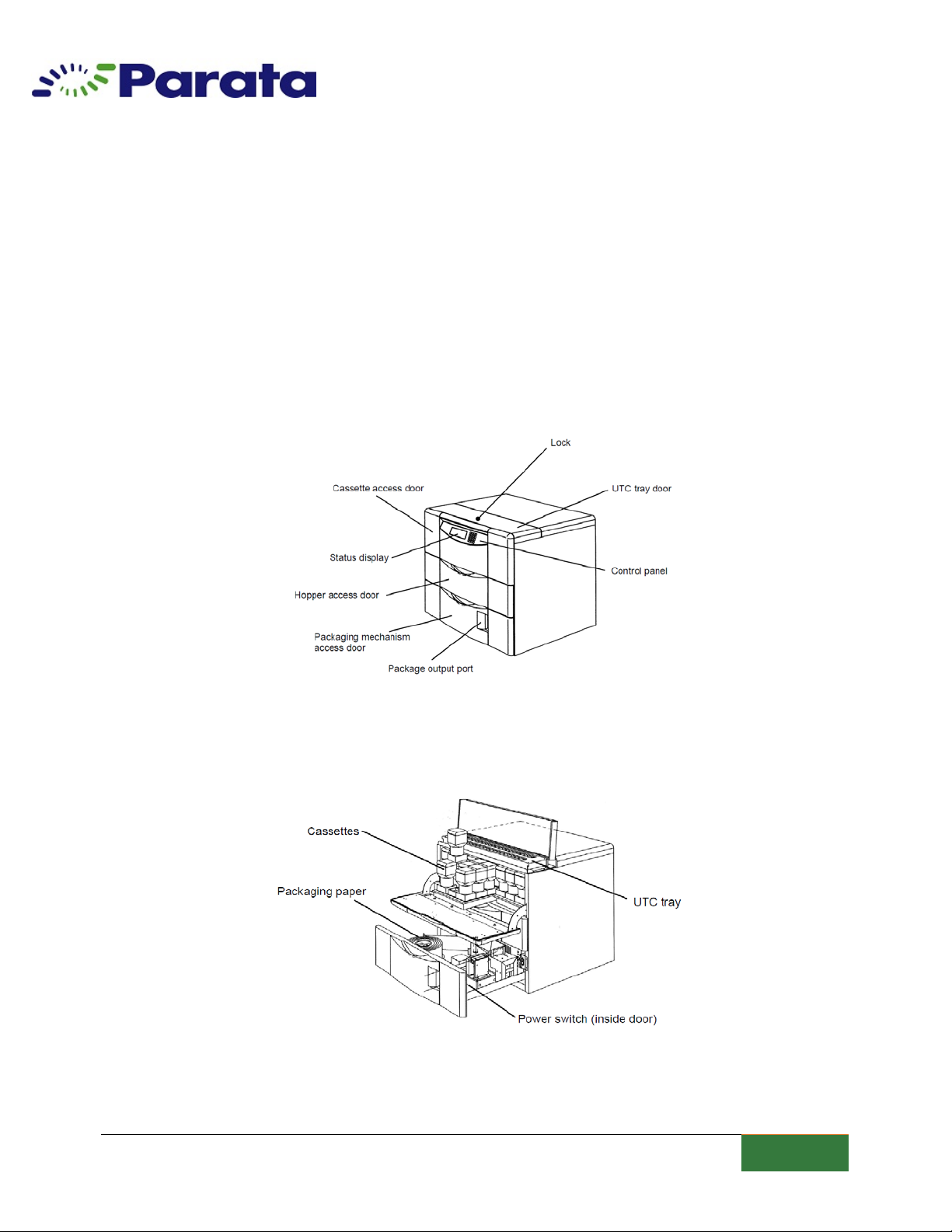
ATP-71 Device Maintenance & Cleaning TD79
| CHAPTER 1: INSTALLATION
9
General Warnings and Cautions
Warning: Failure to observe these and any other warnings contained in
this manual may result in hazards causing serious injury or death.
•This system cannot dothe jobofa registered pharmacist. An appropriate quality
checking system should be used to ensure dispensing accuracy.
•Use only parts andsupplies approved by Parata isnot responsible for any quality
problems resulting from parts and/or supplies not approved by Parata.
•Do not usethe ATP-71system outdoors. Current leakage or electric shock may result if
the system isexposed to water.
•Only qualified service personnel should install and service the ATP-71system. Installation
and service by unqualified personnel may result inshock orfire.
•Never locate the ATP-71system in a humid place or a place where it is likely to be
splashed by water. Humidity may cause the insulation to deteriorate, causing current
leakage andpossible electric shock.
•Usea power source rated for a minimum of 15A. Ensure that both the plug andthe
outlet are free ofdust. Do not use a branched outlet, asthis may result inan increased
risk of fire.
•In the event of operational problems, disconnect the ATP-71 from its power source until
it can beserviced byqualified personnel.
•Always disconnect the ATP-71from its power source prior to performing any
maintenance orrepair service toprevent serious injury or death.
•Use a power supply ground.
•Never disassemble, repair, ormodify the ATP-71system. Unauthorized modifications
may result in serious injury or death.
•Never ground the ATP-71system to a gas pipe, water main, telephone line, or lightning
rod. Such grounding may cause serious injury ordeath if an incomplete circuit is formed.
•Do not insert metal objects into any vent, gap. Oroutlet outside orinside the ATP-71
cabinet, as this may cause serious injury or death.
•Never insert fingers orobjects into the package output port, asthis may cause serious
injury during system operation.
•Never touch the gold-colored heater blocks inside theATP-71packaging drawer,
regardless of whether the system is off-line or online.
•Never touch the blade orheater block in the heat sealer when replacing the paper roll or
cleaning the system.
•Use ATP-71tablet canisters only with their designated medication.
•Be sure to verify that the correct medication is used when refilling canisters.
•Never touch electrical components orswitches with wet hands, asthis may result in
serious injury ordeath.