Heliporter®
H250TP Operation
5. Raise the lifting platform slowly by pulling aft on the platform control until the Heliporter®
lift pads make contact with the aircraft pickup points. Release the platform control stick and
pump switch.
6. With proper alignment achieved and with the pump switch off, rotate the twist grip forward
to the spring loaded “Neutral” position. This will engage the hydrostatic brakes and prevent
the from moving as the helicopter's skids leave the ground. Re-engage the pumpHeliporter®
and continue to raise the platform.
7. When the desired height is achieved, release the platform control and hydraulic pump
switch. With controls released, the aircraft will remain in the desired position.
Caution: The helicopter can inadvertently be lowered by pushing forward on the platform
control without the hydraulic pump operating. An abrupt forward movement of the platform
control will cause rapid lowering of the helicopter, possibly causing damage to the aircraft or
personnel. With the weight of the helicopter on the ground, it may be necessary to use the
hydraulic pump to fully lower the platform.
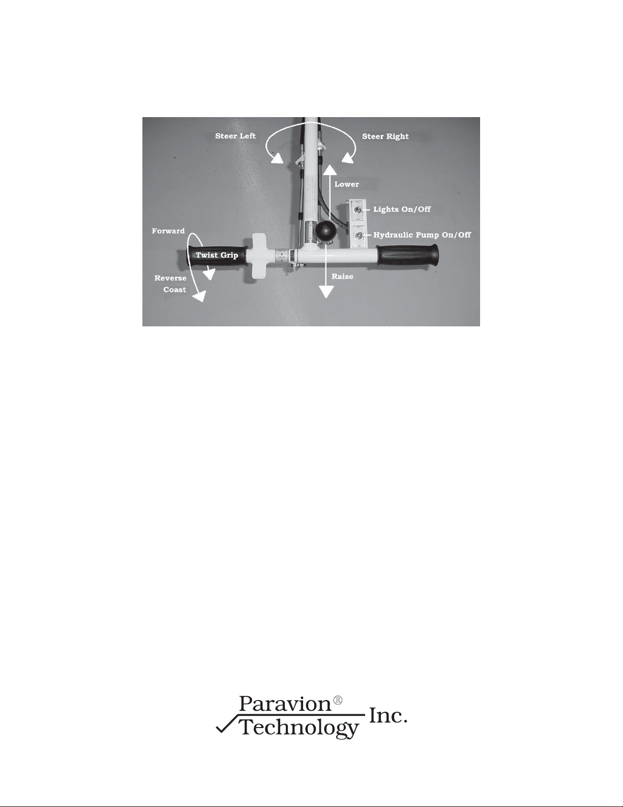
8. The twist grip (see Fig. 1) controls forward and aft movement of the , it also controlsHeliporter®
the throttle speed. The speed is determined by the degree of rotation to the twist grip. A small
rotation will move the slowly and full rotation will move the at fullHeliporter Heliporter
® ®
speed of 2.5 mph .
Caution: When engaging the hydrostatic drive, rotate the twist grip .slowly
9. To move a helicopter while being supported on the lifting platform, engage the hydraulic pump
switch and rotate the left hand grip forward to move rearward. To move forward, rotateslowly
the left handgrip aft (See Fig. 1).slowly
10. When the aircraft is raised and proper speed and direction are achieved, the operator can move
the entire control handle assembly to the right or left of the aircraft to facilitate viewing the area
toward which the aircraft is moving.
CAUTION: Never take off or land over the .Heliporter®
www.paravion.com
Phone: (970) 224-3898
Fax: (970) 224-3899
8