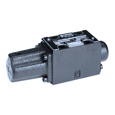
Parker Hydraulics GRESEN V10 User manual

Hydraulics
GRESEN
R
Model V10
Sectional Body
Directional Control Valve
Service Manual
Maximum Operating Pressure: 3 00 PSI (242 bar)
Minimum Filtration Required: 10 Micron
for the Model V10 Directrional Control Valve. If further
assistance is required, contact your Parker Distributor
or Representative.
Rev: 01-01-2005 (Replaces: Revision 8/01/02)
Bulletin HY14-2701-M1/US - TORO Specific

Model V10 Service Bulletin HY14-2701-M1/US - TORO Specific
Revision: 01-01-2005
!W A R N IN G
FAILURE OR IMPROPER SELECTION OR IMPROPER USE OF THE PRODUCTS AND/OR SYSTEMS DESCRIBED HEREIN OR RELATED ITEMS
CAN CAUSE DEATH, PERSONAL INJURY AND PROPERTY DAMAGE.
This document and other information from Parker Hannifin Corporation, its subsidiaries and authorized distributors provide product and/or system
options for further investigation by users having technical expertise. It is important that you analize all aspects of your application and review the
information concerning the product or system in the current product catalog. Due to the variety of operating conditions and application for these products
or systems, the user, through its own analysis and testing, is solely responsible for making the final selection of the products and systems and assuring
that all performance, safety and warning requirements of the application are met.
The products described herein, including without limitation, product features, specifications, designs, availability and pricing, are subject to change by
Parker Hannifin Corporation and its subsidiaries at any time without notice.
Offer of Sale
The items described in this document are hereby offered for sale by Parker Hannifin Corporation, its subsidiaries or its authorized distributors. This offer
and its acceptance are governed by the provisions stated in the “Offer of Sale”.
© Copyright 2004, Parker Hannifin Corporation, All Rights Reserved
Parker Hannifin Corporation
Hydraulic Valve Division
Elyria, Ohio USA
www.parker.com/hydraulicvalve
2

Model V10 Service Bulletin HY14-2701-M1/US - TORO Specific
Revision: 01-01-2005
Table of Contents
Assembly Studs ........................................................................................................................................................................ 4
Section Seal Kits ...................................................................................................................................................................... 5
Procedures for Removing Model V10 Spool Seals .................................................................................................................. 6
Procedures for Installing Model V10 Spool Seals .................................................................................................................... 7
Special Note Regarding Back-Up Rings ................................................................................................................................... 8
Power Beyond Sleeve (machines with front loader only) .......................................................................................................... 9
Spring Return Spool Positioner ............................................................................................................................................... 10
4-Position Float Spool Positioner ............................................................................................................................................ 11
5-Position Float Spool Positioner ............................................................................................................................................ 12
Work Port Cavity Plug ............................................................................................................................................................. 13
Extended Handle Assembly ....................................................................................................................................................14
Joystick Assembly .................................................................................................................................................................. 15
Joystick Adapter Plate Assembly ............................................................................................................................................ 16
3

Model V10 Service Bulletin HY14-2701-M1/US - TORO Specific
Revision: 01-01-2005
4
Assembly Studs
Torque to Maximum 13 - 15 Ft Lbs (17 - 20 Nm) For Dry Tie Bolts
Torque to Maximum 10 - 13 Ft Lbs (13 - 17 Nm) For Oiled Tie Bolts
23
1
CAUTION
If the stud nuts are not tightened to the proper torque, valve spools may bind or stick, or cause O-Ring
seals to extrude.
Figure 1. Assembly Studs
Ref No. Description Quantity
1
2
3
4
Single Section Stud
Two Section Stud
Section Seal Kit (See Page 5)
Nut
Bracket (Short) for manual valves
A/R
8
2
2
2
4

Model V10 Service Bulletin HY14-2701-M1/US - TORO Specific
Revision: 01-01-2005
5
Section Seal Kits
Section Seals are located in the Inlet Cover and in the downstream side of all work sections
Important: Do Not lubricate section seals
prior to installation. Install dry.
Manual Work Sections
11
2
1
Figure 2. Section Seal Identification
Section Seal Kits
Ref No. Description Quantity
1
2
3
1
Section Seal Replacement Precautions
•Do not lubricate the O-Ring section seals
prior to installation. Compression of
lubricants can distort the valve body causing
spool bind.
•If the stud nuts are not torqued to the
proper specifications, valve spools may bind or
stick, or cause O-Ring seals to extrude.
•Replace the stud nuts and torque evenly to 13 -
15 Ft Lbs [17 - 20 Nm]. This is a dry stud
torque spec. Torque evenly to 10 - 13 Ft Lbs
[13 - 17 Nm] for oily studs.
Buna-N seals are standard for all Parker valve assemblies.
Section Seal Kit (Kit Includes Items 1 and 2 Only)
O-Ring Section Seal (Open Center and Exhaust Counterbores)
O-Ring Section Seal (Power Core Counterbore)

Model V10 Service Bulletin HY14-2701-M1/US - TORO Specific
Revision: 01-01-2005
6
Procedures for Removing Model V10 Spool Seals
Handle End Positioner End
1. Remove the handle and positioner hard-
ware from the valve section.
2. Insert a punch or screwdriver through the
spool clevis. While watching the positioner
end, slowly pull the spool toward the handle
end. Stop when the spool seal is exposed
as shown.
3. Using a small seal pick, carefully
remove the spool seal from the positioner
end.
4. Push the spool back through the housing
and out the positioner end.
5. Remove the remaining spool seal with
the seal pick.
AB
AB
AB
Figure 3. Model V10 Spool Seal Removal

Model V10 Service Bulletin HY14-2701-M1/US - TORO Specific
Revision: 01-01-2005
7
Procedures for Installing Model V10 Spool Seals
Handle End Positioner End
1. Lightly lube and insert the handle end Spool Seal first.
Verify seal fit by carefully running your finger around
the exposed edge of the seal. You should have a
smooth, perfect ridge with no kinks or twists.
2. Lightly oil the valve spool. Using a slight twisting motion,
carefully re-introduce the spool into the valve housing,
starting from the positioner end. Do NOT force the spool
into housing. Once started, the spool should float freely
through the housing until it comes in contact with the spool
seal. Carefully push the spool through the spool seal with a
twisting motion.
3. While watching from the positioner end, pull the spool
into the housing from the handle end. Stop when the seal
groove is exposed.
If the spool is pulled in too far, the spool notches may be
moved into the seal area on the handle end of the housing.
If this happens Do NOT force the spool back out the
positioner end of the housing. Carefully remove the spool
by pulling it out the handle end of the housing. Once the
spool is removed, inspect the front spool seal and replace if
damaged.
4. Lightly lube and install the remaining spool seal. Once
again using a twisting motion, push the spool through the
spool seal.
5. Return the valve spool to the center position and re-
attach the handle and positioner hardware.
Install 'Lip' In as Shown.
AB
AB
AB
Note: The spool may be reversed in V10 Valve Housings for ‘B’ Port Handle requirements.
Figure 4. Model V10 Spool Seal Installation

Model V10 Service Bulletin HY14-2701-M1/US - TORO Specific
Revision: 01-01-2005
8
Special Note Regarding Back-Up Rings
Back-Up Rings in Used Seal Kits
Many of the plugs and cartridges used in the Parker
product line utilize back-up rings. Therefore, many of
the seal kits in this Service Manual include back-up
rings, some of which are continuous back-up rings.
Since the continuous back-up rings are installed at the
factory using a special sizing tool, only replace this
back-up ring if it has been damaged.
(Continuous) Back-Up Ring
Preparing the Back-Up Ring for Installation
If the continuous back-up ring should need
replacing, follow these simple procedures.
1
2
1. Using a single edge razor blade, carefully cut
through the back-up ring in an angle as
shown in the drawing.
Caution: Make only one diagonal cut thru the
back-up ring.
Do not
separate the ring into two
pieces.
2. Slip the back-up ring over the cartridge and
into place.
Carefully make one cut thru Back-Up Ring at
approximately 30 degree angle as shown here.

Model V10 Service Bulletin HY14-2701-M1/US - TORO Specific
Revision: 01-01-2005
9
Power Beyond Sleeve (machines with front loader only)
Torque Option Cavity Cartridge
To: 18 - 20 Ft Lbs [24 - 27 Nm]
1
2
3
4
Power Beyond Sleeves
(for front loader equipped machines)
Figure 5. Power Beyond Sleeve (machines with front loader only)
Ref No. Description Quantity
1
2
3
4
SAE 10 Power Beyond Kit, Complete
Power Beyond Sleeve (SAE 10)
O-Ring Seal
Back-Up Ring
O-Ring Seal
1
1
1
1
Buna-N seals are standard for all Parker valve assemblies.
Continuous Back-Up Rings are installed at the factory using special sizing tools. It is Not necessary to replace the original Back-
Up Rings unless they have been damaged. See Page 8 for Back-Up Ring Preparation and Installation procedures.

Model V10 Service Bulletin HY14-2701-M1/US - TORO Specific
Revision: 01-01-2005
10
Spring Return Spool Positioner
5
43121
Torque to: 4 - 5 Ft Lbs
(6 - 7 Nm)
Torque to: 5 - 6 Ft Lbs
(7 - 8 Nm)
Figure 6. Spring Return Spool Positioner
Ref No. Description Quantity
1
2
3
4
5
‘SC’ Spool Positioner Kit, Complete
Spring Collar
Centering Spring
5/16 - 24 Spool Screw
Bonnet
Bonnet Screw #10-24 X .375
2
1
1
1
4
For identification purposes, these parts are black.
Clean threads and apply Loctite No. 242 (Blue) thread locking adhesive prior to installation.
Unless otherwise specified, mount bonnet with drain slot down toward valve mounting feet.

Model V10 Service Bulletin HY14-2701-M1/US - TORO Specific
Revision: 01-01-2005
11
4-Position Float Spool Positioner
15
Torque To:
5 - 6 Ft Lbs
[7 - 8 Nm]
14
13
5
7
9
6
4
1
2
11
12 8
Torque To:
4 - 5 Ft Lbs
[6 - 7 Nm] Note: This Float Positioner may only be used with the 24990
Work Section Housings having this machined groove
on the end to accept the detent sleeve (Ref. No. 8).
3
10
Apply NLGI #2 Heavy Duty General
Purpose Grease to Surfaces of Ref.
No's. 4, 5, 6 & 8. Insert Spring and
Large Detent Ball (Ref. No's. 5 and 6)
into spool first. Compress spring
when inserting the Small
Detent Balls (Ref No. 4).
Figure 7. 4-Position Float Spool Positioner
Note: Float Positioner Kit Is For Servicing The Newer Float Spool Design In The 24990 Housing With
The Machined Positioner Sleeve Groove Shown In The Above Drawing.
Ref No. Description Quantity
1
2
3
4
5
6
7
8
9
10
11
12
13
14
15
Float Positioner Kit for 24990 Housings with Groove, Complete
Spool Sleeve
O-Ring Seal
Back-Up Ring
.250 Diameter Detent Ball
Detent Spring
.312 Diameter Detent Ball
O-Ring Seal
Float Detent Sleeve
Inner Spring Collar
Spring
Outer Spring Collar
Positioner Spud
Bonnet Spacer
Bonnet
Bonnet Screw #10-24 X 1.75
1
1
1
4
1
1
1
1
1
1
1
1
1
1
4
Buna-N seals are standard for all Parker valve assemblies.
Unless otherwise specified, mount bonnet with drain slot down toward valve mounting feet.
This Float Positioner may only be used with the 24990 Work Section Housings having this machined groove on the end to
accept the detent sleeve (Ref. No. 8).
Apply NLGI #2 Heavy Duty General Purpose Grease to surface prior to installation.

Model V10 Service Bulletin HY14-2701-M1/US - TORO Specific
Revision: 01-01-2005
12
5-Position Float Spool Positioner
15
Torque To:
5 - 6 Ft Lbs
[7 - 8 Nm]
14
13
5
7
9
6
4
1
2
11
12 8
Torque To:
4 - 5 Ft Lbs
[6 - 7 Nm] Note: This Float Positioner may only be used with the 24990
Work Section Housings having this machined groove
on the end to accept the detent sleeve (Ref. No. 8).
3
10
Apply NLGI #2 Heavy Duty General
Purpose Grease to Surfaces of Ref.
No's. 4, 5, 6 & 8. Insert Spring and
Large Detent Ball (Ref. No's. 5 and 6)
into spool first. Compress spring
when inserting the Small
Detent Balls (Ref No. 4).
Figure 8. 4-Position Float Spool Positioner
Note: Float Positioner Kit Is For Servicing The Newer Float Spool Design In The 24990 Housing With
The Machined Positioner Sleeve Groove Shown In The Above Drawing.
Ref No. Description Quantity
1
2
3
4
5
6
7
8
9
10
11
12
13
14
15
Float Positioner Kit for 24990 Housings with Groove, Complete
Spool Sleeve
O-Ring Seal
Back-Up Ring
.250 Diameter Detent Ball
Detent Spring
.312 Diameter Detent Ball
O-Ring Seal
Float Detent Sleeve
Inner Spring Collar
Spring
Outer Spring Collar
Positioner Spud
Bonnet Spacer
Bonnet
Bonnet Screw #10-24 X 1.75
1
1
1
4
1
1
1
1
1
1
1
1
1
1
4
Buna-N seals are standard for all Parker valve assemblies.
Unless otherwise specified, mount bonnet with drain slot down toward valve mounting feet.
This Float Positioner may only be used with the 24990 Work Section Housings having this machined groove on the end to
accept the detent sleeve (Ref. No. 8).
Apply NLGI #2 Heavy Duty General Purpose Grease to surface prior to installation.

Model V10 Service Bulletin HY14-2701-M1/US - TORO Specific
Revision: 01-01-2005
13
Work Port Relief Cavity Plug
Torque Relief Cavity Plug To:
18 - 20 Ft Lbs [24 - 27 Nm]
4
123
Figure 9. Work Port Relief Cavity Plug
Ref No. Description Quantity
1
2
3
4
Plug Seal Kit (Includes Ref No’s. 2 thru 4 Only)
NR Plug
O-Ring Seal
Back-Up Ring
O-Ring Seal
1
1
1
1
Buna-N seals are standard for all Parker valve assemblies. Contact the Parker factory for optional seals.
Continuous Back-Up Rings are installed at the factory using special sizing tools. It is Not necessary to replace the original
Back-Up Rings unless they have been damaged. See Page 8 for Back-Up Ring Preparation and Installation procedures.

1
4
9
10
3
7
26
5
8
Torque Ref No. 4 to
5 - 6 Ft Lbs [7 - 8 Nm]
Apply General Purpose
Grease to Clevis Pin (Ref No. 8)
Prior to Installing Handle Assembly
Torque Ref No. 4 to
4 - 5 Ft Lbs [6 - 7 Nm]
Coat Flat End, Pin Hole, And Slot Of
Handle Rod (Item 2) With Grease (Mobile
DTH Or Equivalent) Prior To Installing
The Handle Assembly
Press Pin (Item 5) Below The
Surface And Stake Both Sides
Extended Handle Assembly
Figure 10. Extended Handle Assembly
Extended Handle Kit (Contains Items 1 thru 9 Only)
Handle Bracket
Horizontal Handle Rod
Dust Boot
Long Bracket Screw #10-24 X 2.75
Dowel Pin 3/16” X 1/2”
Handle Knob
Handle Extension
Clevis Pin 3/16” X 3/4”
Cotter Pin 5/64” X 1/2”
(Extended) Spool Clevis
Ref No. Description Quantity
1
2
3
4
5
6
7
8
9
10
Model V10 Service Bulletin HY14-2701-M1/US - TORO Specific
Revision: 01-01-2005
14
1
1
1
4
1
1
1
1
1
1

Model V10 Service Bulletin HY14-2701-M1/US - TORO Specific
Revision: 01-01-2005
15
Joystick Assembly
1
12
11
3
7
6
8
5
4
2
10
9
Torque to:
5 - 6 Ft. Lbs.
(7 - 8 Nm)
Torque to:
13 - 15 Ft. Lbs.
(17 - 19 Nm)
Torque to:
5 - 6 Ft. Lbs.
(7 - 8 Nm)
Torque to:
13 - 15 Ft. Lbs.
(17 - 19 Nm)
13
13
Torque to:
4 - 5 Ft. Lbs.
(5 - 6 Nm)
Torque to:
4 - 5 Ft. Lbs.
(5 - 6 Nm)
Figure 11. Joystick Assembly
Ref No. Description Quantity
1
2
3
4
5
6
7
8
9
10
11
12
13
Joystick Assembly Kit, Complete
Base Plate Bracket
Screw .312 - 24 X 1.25
Screw #10 - 24 X .75
Joystick Adapter Plate Assembly (See Figure 12)
Spacer
Rod End (.312 – 24 Female)
Slide Pin
Lock Nut .312 – 24 UNF
Boot
Screw .312 - 24 X .75
Screw #10 - 24 X 1.25
Boot Support Bracket
Joystick Spool Clevis - Required for Mechanical Joysticks (24990 Housings)
1
1
2
1
2
1
1
2
1
1
1
1
2
This Mechanical Joystick Assembly does NOT include the Joystick Handle.
Clean threads and apply Loctite No. 262 (Red) thread locking adhesive prior to installation.

Model V10 Service Bulletin HY14-2701-M1/US - TORO Specific
Revision: 01-01-2005
16
Joystick Adapter Plate Assembly
1
1
5
2
3
6
Torque to: 35 - 37 Ft Lbs
(48 - 51 Nm)
Torque to: 11 - 13 Ft Lbs
(15 - 18 Nm)
Align Both Rod Ends As
Shown When Installing
Assemble With Handle Plate and Rod
End This Way For Joystick
Assemble With Handle Plate and Rod
End This Way For Right-Hand Joystick
Figure 12. Joystick Adapter Plate Assembly
Ref No. Description Quantity
1
2
3
4
5
6
Screw .312 – 24 X .75
Rod End 5/16 - 24 Female
Screw 3/8 - 16 X 1.00
Handle Plate
Handle Adapter
Rod End - Special
2
1
1
2
1
1
Clean threads and apply Loctite No. 262 (Red) thread locking adhesive prior to installation.
Rod ends must be aligned as show in the above drawing for Left or Right-Hand Installation.
Table of contents
Other Parker Hydraulics Control Unit manuals
Popular Control Unit manuals by other brands

Puls
Puls DIMENSION PISA-B-8CL2-B4 installation manual

Cornelius
Cornelius UF-1 Training manual

Jefferson Solenoid Valves U.S.A. Inc.
Jefferson Solenoid Valves U.S.A. Inc. Z1314BV**AT Z1314BLV24AT Installation and Maintenance

AVG
AVG PRV25F installation instructions

Boyertown Furnace
Boyertown Furnace PurePro Energy Manager PRO 6000Z installation instructions

IKUSI
IKUSI SPI-300 Basic handling