Parker IQAN-XT2 User manual

IQAN-XT2
Instruction book
Publ no HY33-8313-IB/UK
Edition 2012-11-06

ii
Contents
Instruction book, IQAN-XT2
Contents
1 Introduction . . . . . . . . . . . . . . . . . . . . . . . . . . . . . . . . . . . . . . . . . . . . . . . . . . . . 1
Warnings . . . . . . . . . . . . . . . . . . . . . . . . . . . . . . . . . . . . . . . . . . . . . . . . . . . . 1
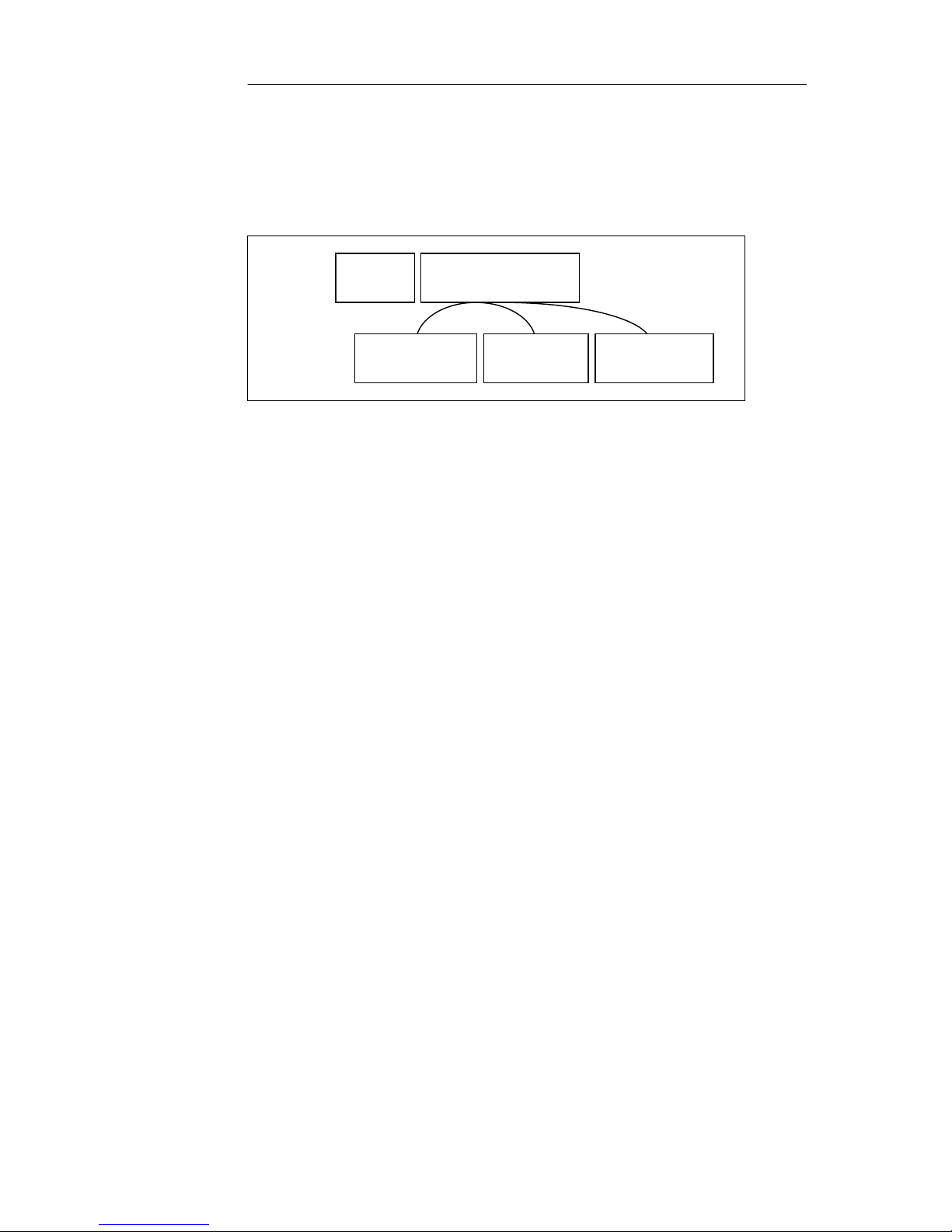
Overview of relevant documentation . . . . . . . . . . . . . . . . . . . . . . . . . . . . . . . 2
2 Precautions . . . . . . . . . . . . . . . . . . . . . . . . . . . . . . . . . . . . . . . . . . . . . . . . . . . . 3
Read This . . . . . . . . . . . . . . . . . . . . . . . . . . . . . . . . . . . . . . . . . . . . . . . . . . . . 3
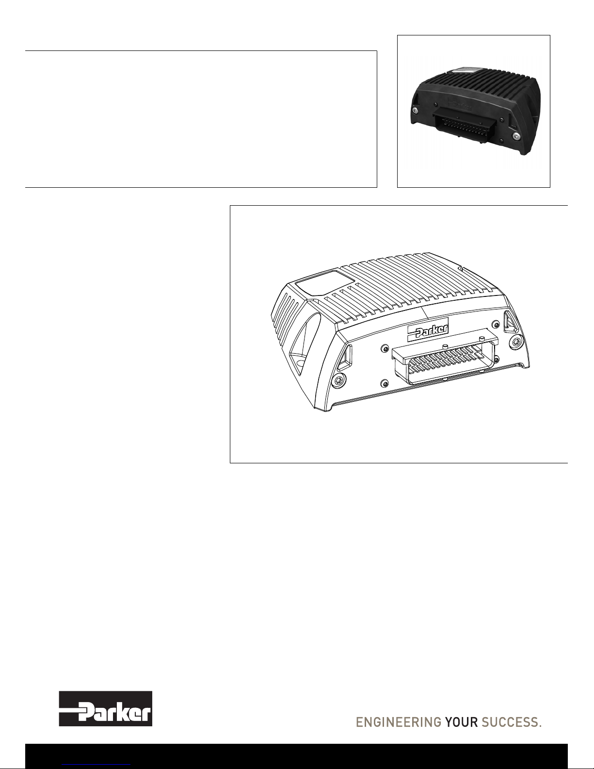
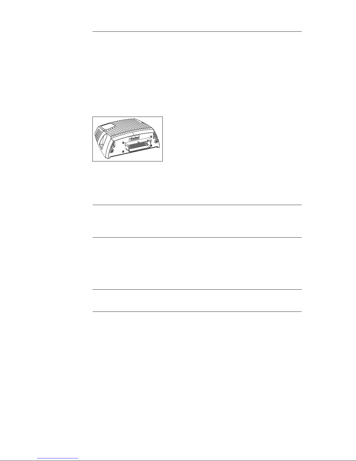
3 Product description . . . . . . . . . . . . . . . . . . . . . . . . . . . . . . . . . . . . . . . . . . . . . 5
IQAN-XT2 . . . . . . . . . . . . . . . . . . . . . . . . . . . . . . . . . . . . . . . . . . . . . . . . . . . . 5
4 Safety . . . . . . . . . . . . . . . . . . . . . . . . . . . . . . . . . . . . . . . . . . . . . . . . . . . . . . . . . 6
Internal diagnostics . . . . . . . . . . . . . . . . . . . . . . . . . . . . . . . . . . . . . . . . . . . . 6
CAN-bus interruption . . . . . . . . . . . . . . . . . . . . . . . . . . . . . . . . . . . . . . . . . . . 6
Current check . . . . . . . . . . . . . . . . . . . . . . . . . . . . . . . . . . . . . . . . . . . . . . . . . 6
Emergency stop . . . . . . . . . . . . . . . . . . . . . . . . . . . . . . . . . . . . . . . . . . . . . . . 6
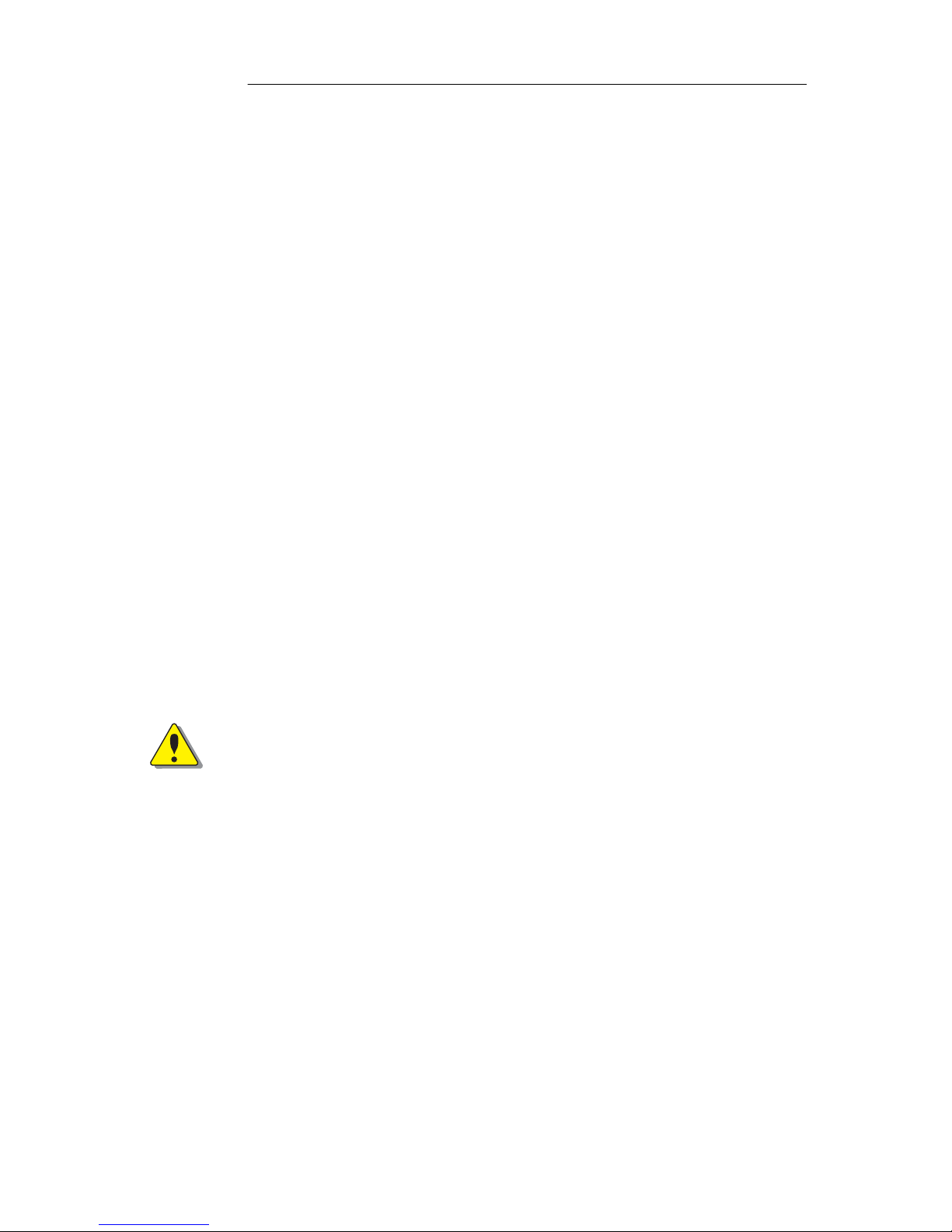
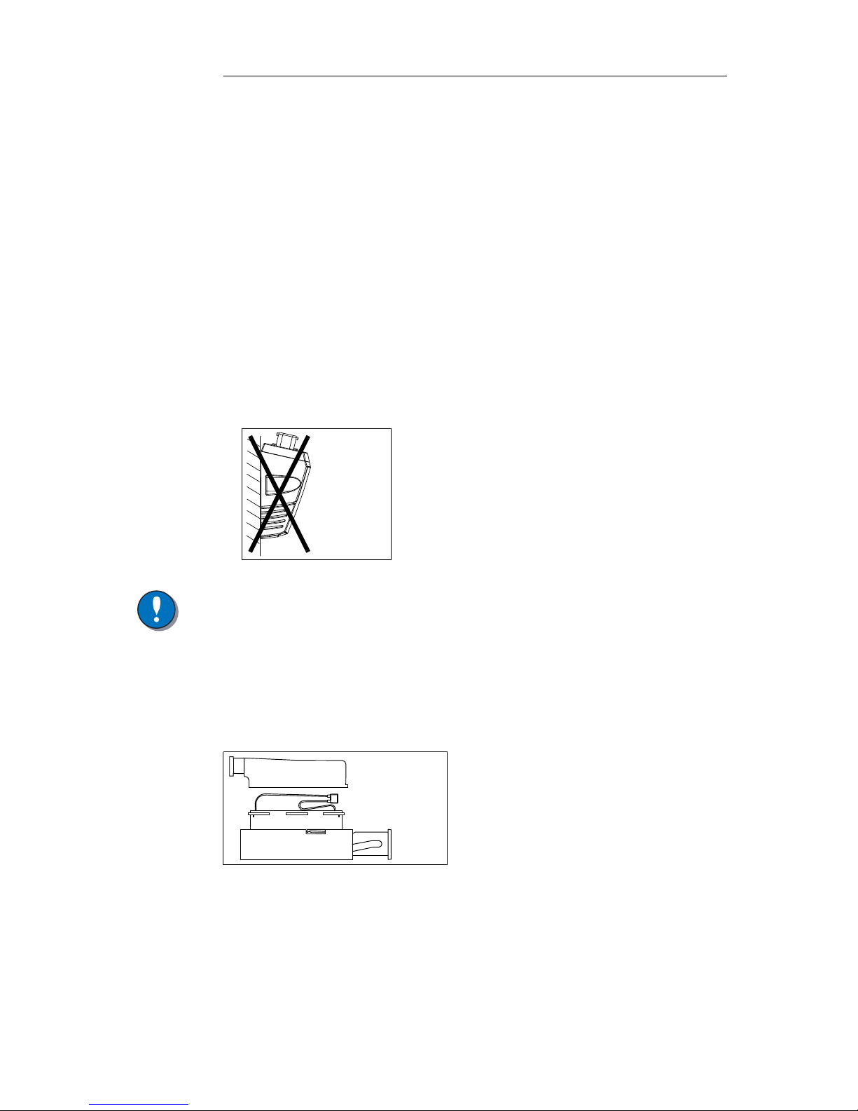
5 Mounting . . . . . . . . . . . . . . . . . . . . . . . . . . . . . . . . . . . . . . . . . . . . . . . . . . . . . . 7
Mounting the module . . . . . . . . . . . . . . . . . . . . . . . . . . . . . . . . . . . . . . . . . . . 7
6 Installation . . . . . . . . . . . . . . . . . . . . . . . . . . . . . . . . . . . . . . . . . . . . . . . . . . . . . 8
Connector C1 . . . . . . . . . . . . . . . . . . . . . . . . . . . . . . . . . . . . . . . . . . . . . . . . . 8
Supply voltage . . . . . . . . . . . . . . . . . . . . . . . . . . . . . . . . . . . . . . . . . . . . . . . . 9
IQAN-XT2 addressing/terminating . . . . . . . . . . . . . . . . . . . . . . . . . . . . . . . . 10
CAN connection . . . . . . . . . . . . . . . . . . . . . . . . . . . . . . . . . . . . . . . . . . . . . . 11
Reference voltage, VREF . . . . . . . . . . . . . . . . . . . . . . . . . . . . . . . . . . . . . . 11
Voltage inputs . . . . . . . . . . . . . . . . . . . . . . . . . . . . . . . . . . . . . . . . . . . . . . . 12
Frequency inputs . . . . . . . . . . . . . . . . . . . . . . . . . . . . . . . . . . . . . . . . . . . . . 15
Current outputs . . . . . . . . . . . . . . . . . . . . . . . . . . . . . . . . . . . . . . . . . . . . . . 16
Digital outputs . . . . . . . . . . . . . . . . . . . . . . . . . . . . . . . . . . . . . . . . . . . . . . . 17
PWM outputs . . . . . . . . . . . . . . . . . . . . . . . . . . . . . . . . . . . . . . . . . . . . . . . . 19
E-GAS outputs . . . . . . . . . . . . . . . . . . . . . . . . . . . . . . . . . . . . . . . . . . . . . . . 20
7 Start-up . . . . . . . . . . . . . . . . . . . . . . . . . . . . . . . . . . . . . . . . . . . . . . . . . . . . . . . 21
Start-up procedures . . . . . . . . . . . . . . . . . . . . . . . . . . . . . . . . . . . . . . . . . . . 21
8 System Diagnostics . . . . . . . . . . . . . . . . . . . . . . . . . . . . . . . . . . . . . . . . . . . . 22
Appendix A . . . . . . . . . . . . . . . . . . . . . . . . . . . . . . . . . . . . . . . . . . . . . . . . . . . 23
IQAN-XT2 Technical Overview . . . . . . . . . . . . . . . . . . . . . . . . . . . . . . . . . . 23
Appendix B . . . . . . . . . . . . . . . . . . . . . . . . . . . . . . . . . . . . . . . . . . . . . . . . . . . 27
Error codes, messages and actions . . . . . . . . . . . . . . . . . . . . . . . . . . . . . . . 27
Appendix C . . . . . . . . . . . . . . . . . . . . . . . . . . . . . . . . . . . . . . . . . . . . . . . . . . . 30
Dimensioning of the IQAN-XT2 module . . . . . . . . . . . . . . . . . . . . . . . . . . . . 30

1
Warnings
1 Introduction
Instruction book, IQAN- XT2
1 Introduction
These instructions are to be used as a reference tool for the vehicle manufacturer’s
design, production, and service personnel.
The user of these instructions should have basic knowledge in the handling of
electronic equipment.
Warnings
Sections marked with a symbol in the left margin, must be read and understood by
everyone using the system, carrying out service work, or making changes to hardware
and software.
The different symbols used in this manual are defined below.
WARNING
Sections labeled WARNING with a caution symbol in the left margin, indicate that a
hazardous situation exists. We use warnings, marked with the warning symbol, in two
ways.
• As a strong recommendation about work practices when using the product in the
machine (e.g. routines when updating an application). This use is common to the
term 'hazardous situation', that a person is exposed to a hazard.
• As a way of pointing out important information for the machine designer that in
some way relates to safety. This includes the design of the physical machine, and
also the application program being developed for the control system.
Not all document sections that contain information about safety are marked with a
warning symbol (there would be warnings everywhere). Failure to comply with the
recommendations can cause unintentional, and unexpected behavior of the control
system. This can potentially cause death, serious injury or property damage.
NOTICE
Sections labeled NOTICE with a notice symbol in the left margin, indicate there is
important information about the product. Ignoring this could result in less than optimal
performance, or damage to the product.
Contact the manufacturer if there is anything you are not sure about or if you have any
questions regarding the product and its handling or maintenance.
The term "manufacturer" refers to Parker Hannifin Corporation.

2
Overview of relevant documentation
1 Introduction
Instruction book, IQAN- XT2
Overview of relevant documentation
The following publications are relevant for users of this product.
The main documentation contains information that is not found elsewhere.
The additional documentation contains product information in a compact format, for
details on the information found in those documents, consult this manual.
The IQAN-XT2 module documentation system.
IQANdesign/
IQANdevelop
User Manual
IQAN-XT2 Instruction Book
HY33-8313-IB
(thisbook)
IQAN-XT2
Catalogue Datasheet
HY33-8313
IQAN-XT2
Installation Sheet
HY33-8313-IS
IQAN-XT2
Electrical Schematic
HY33-8313-ES
Compact
Documentation
Main
Documentation

3
Read This
2 Precautions
Instruction book, IQAN- XT2
2 Precautions
Work on the hydraulics control electronics may only be carried out by trained
personnel who are well-acquainted with the control system, the machine and its safety
regulations.
WARNING
Make sure that you have sufficient knowledge before designing, modifiying or
servicing the control system.
Read the relevant sections of this document before conducting any work on the control
system.
WARNING
This product is not field repairable.
NOTICE
As much as possible of the welding work on the chassis should be done before the
installation of the system. If welding has to be done afterwards, the electrical
connections on the system must be disconnected from other equipment. The negative
cable must always be disconnected from the battery before disconnecting the positive
cable. The ground wire of the welder shall be positioned as close as possible to the
place of the welding. The cables on the welding unit shall never be placed near the
electrical wires of the control system.
Read This
Design of control system
WARNING
Risk of injury may be introduced by design of control system!
This product is designed to control hydraulic outputs. The control application must be
designed using basic safety principles so that unintentional movement is avoided.
The machine must be equipped with an emergency stop that stops all movement. Please
refer to section Emergency stop, on page 9.
Before you start
Read this document, as a minimum sections 1-7
Read the IQANdesign software user manual section on 'application safety'.

4
Read This
2 Precautions
Instruction book, IQAN- XT2
Start-up, maintenance, and diagnostics
For all personnel carrying out installation, commissioning, maintenance or
troubleshooting.
WARNING
Work on the hydraulics control electronics may only be carried out by trained
personnel who are well-acquainted with the control system, the machine and its safety
regulations.
Before you start,
Read section Start-up, on page 21.
Additional information for service
Mounting and maintenance instruction book.
Additional information for diagnosing the system
Read section System Diagnostics, on page 22, and see Appendix B, on page 27, in this
document.
Use the IQANrun/IQANdevelop software user manual as a reference.

5
IQAN-XT2
3 Product description
Instruction book, IQAN- XT2
3 Product description
IQAN-XT2
The IQAN-XT2 is one out of several expansion modules designed for controlling
hydraulic systems in vehicles and machinery, using 12/24 Vdc power supply.
The IQAN-XT2 is able to be used in both IQANdevelop platform and IQANdesign
platform systems.
The IQAN-XT2 module.
Input
The IQAN-XT2 module has 10 voltage inputs for connecting of 0-5 Vdc signals.
VIN-H thru VIN-J can be configured as frequency inputs for measuring frequency.
Voltage inputs and frequency inputs, share positions, see below.
Output
The IQAN-XT2 module has two (2) double current outputs that are regulated for
controlling proportional valves. The module also has six (6) digital outputs for on/off
valves which can be configured as either six (6) individual or three (3) double PWM
outputs (Pulse Width Modulation) for non-regulated control of proportional valves and
devices. Digital and PWM outputs share positions, see below.
In order to increase the performance of current outputs when controlling proportional
valves, both the dither frequency and the dither amplitude can be adjusted.
The digital output channels also have soft start and peak & hold features available.
CAN related functions
The master uses the CAN-bus (CAN = Control Area Network) to communicate with
the modules. The CAN-bus is used and well proven within the automotive industry.
(10) Voltage inputs VIN-A, VIN-B, VIN-C, VIN-D.....VIN-J
or
(7) Voltage inputs VIN-A thru VIN-G and (3) Frequency inputs FIN-A thru FIN-C
(2) double Current outputs
(6) Digital outputs, or (3) double PWM outputs

6
Internal diagnostics
4 Safety
Instruction book, IQAN- XT2
4Safety
Internal diagnostics
The module performs a number of self-checks that improve safety. Checks include
monitoring of voltage supplies, checksums on memory and a watchdog that monitors
software execution. The module is using a real time operating system which supervises
software execution.
If a critical error is detected, the module is stopped, with CAN bus and outputs off.
CAN-bus interruption
The IQAN-XT2 communicates with an IQAN master module on the CAN bus. Both
the master and the IQAN-XT2 check for any interruptions in the CAN-bus
communication. If an error occurs the master will use zero or an application defined
error value for the module inputs, and the module outputs will be off.
The error will be indicated both on the master module and with a blink code on the unit;
see Appendix B, on page 27
Current check
For the proportional outputs when used in current mode, a current check is performed.
If an error is detected, this will be indicated on the master module, and the output will
shut off.
The XT2 module can detect open-circuit, short-circuit to +BAT/-BAT or short-circuit
to other proportional output and return pins.
Emergency stop
WARNING
Risk of injury! The emergency stop must disconnect the power supply to the module;
do not connect the emergency stop as a signal input only.
The emergency stop must be installed so that the risk of reverse feed of the module is
avoided, see section Emergency stop, on page 9.

7
Mounting the module
5 Mounting
Instruction book, IQAN- XT2
5 Mounting
Mounting the module
The IQAN-XT2 module should be mounted according to the following instructions:
• Locate the module eliminating the risk for the cabling to be folded, crushed or dam-
aged in any way. Ensure the cabling cannot pull, twist or induce sideload on the con-
nector.
• Locate the module so that severe physical impact is avoided, e.g impact from falling
objects or the module being used as a step.
• Locate the module so that air can circulat to eliminate excess heat. Ensure that no
external heat, e.g. from the engine or heater, is transferred to the module.
• Locate the module to protect it from high pressure washing or similar.
• Locate the module so that the cable connector is facing down .
• Locate the module so that the LEDs are visible.
Non approved placing.
NOTICE
The IQAN-XT2 module must not be placed in any marine related or similar
continuously damp environment without external protection.
Assembling of the ID-Tag
The ID-Tag will be placed in the connector in order to address/ terminate the module,
ref section IQAN-XT2 addressing/terminating, on page 10.
The ID-Tag will be mounted under the connector casing. Bend the ID-Tags´ cables
toward the opposite side of where the other cables enter the connector.
Assembling of the Id-Tag.

8
Connector C1
6 Installation
Instruction book, IQAN- XT2
6Installation
Connector C1
Unshaded positions are Junior Power Timer pins. Shaded positions are Micro Timer II pins. See above for wire, seal, pin
number and crimping tool information. The IQAN tool kit is found in the ’IQAN accessories’ datasheet.
Connector kit Parker no. 5031063
Housing Amp no. 1-963226-1
Casing Amp no. 0-965643-1
Plane sealing, 42 p in module connector
Pin types* Amp no. 963711-2 (MT) Amp no. 929929-1 (JPT)
Cables 0,75-1,0 mm² (MT) 1,5-2,5 mm² (JPT)
Seals Amp no. 963530-1 (MT) Amp no. 828905-1 (JPT)
Plugs (empty pos.) Amp no. 963531-1 (MT) Amp no. 828922 (JPT)
IQAN crimping
tool references
Blue handle, pos. B
use blue extraction tool
Red handle, pos. B
use yellow extraction tool
IQAN tool kit Parker no. 5031061
Pos Signal name Pos Signal name Pos Signal name
1 ADDR-H 15 -BAT 29 -BAT2
2DOUT-A 16 CAN-H 30 CAN-L
3DOUT-B 17 COUT-A 31 COUT-A
4DOUT-C 18 CRET-A+ 32 CRET-A-
5DOUT-D 19 COUT-B 33 COUT-B
6DOUT-E 20 CRET-B+ 34 CRET-B-
7DOUT-F 21 VIN-A/EGAS-RET 35 VIN-F
8EGAS+ 22 VIN-B 36 VIN-G
9EGAS- 23 VIN-C 37 VIN-H/FIN-A
10 +VREF-EGAS 24 VIN-D 38 VIN-I/FIN-B
11 -VREF-EGAS 25 VIN-E 39 VIN-J/FIN-C
12 +VREF 26 CAN2-H 40 CAN2-L
13 -VREF 27 CAN-H 41 CAN-L
14 ADDR-L 28 +BAT
(+12 V, +24 V)
42 +BAT2
(+12 V,+24 V)
*= The connector contains two types
of terminals; MT (Micro Timer) and
JPT (Junior Power Timer).
42
28
14
29
15
1

9
Supply voltage
6 Installation
Instruction book, IQAN- XT2
Supply voltage
Before any installation of the IQAN system can take place, make sure the ignition lock
is turned off and the battery is disconnected.
Emergency stop
Make sure an Emergency Stop disconnecting the power supply, is easily accessible at
any time. The figure below shows how to connect the emergency stop.
Connecting of Supply Voltage
The supply voltage, should be within the operating interval, see Appendix A, on page
23. Connect the supply voltage to +BAT, position 28 and -BAT, position 15. Protect the
module by using a fuse. Requisite fuse level should be 20 A, fast (F).
Connecting the emergency stop and voltage supply.
NOTICE
Do not use the chassis as the negative terminal.
Supplying a high current draw system
If the IQAN-XT2 module is used to control several digital outputs simultaneously, it is
recommended to source power thru the +BAT2 and -BAT2 positions in addition to the
+BAT and -BAT. Requisite fuse level can be max 30 A, fast (F).
EXAMPLE
Connecting the emergency stop and voltage supply.
+-
Emergency Stop
+BAT, pos. 28
20 A
-BAT, pos.15
*
* Symbol for disconnecting
switch for battery, ignition
lock and other fuses.
IQAN-XT2
+-
Emergency Stop
+BAT2, pos.42
30 A
-BAT2, pos.29
*
* Symbol for disconnecting
switch for battery, ignition
lock and other fuses.
+BAT, pos.28
-BAT, pos.15
IQAN-XT2

10
IQAN-XT2 addressing/terminating
6 Installation
Instruction book, IQAN- XT2
IQAN-XT2 addressing/terminating
Addressing
Each IQAN-XT2 module will have a specific address, enabling the master module to
communicate with the modules through the CAN-bus. When operating, the system
distinguishes between different modules by first verifying the module type and
secondly, through the modules having unique addresses.
The maximum number of similar modules in a system is four or eight depending on the
master module, denoted in the first case as addresses 0, 1, 2, 3 respectively. In order to
assign any IQAN-XT2 module a unique CAN-address, an ID-Tag will have to be
connected to the positions ADDR-H and ADDR-L.
Connecting of Id-Tag in IQAN-XT2 connector housing.
Terminating
To eliminate interference in the communication through the CAN-bus, the CAN-bus
must be terminated. Because the master module always is located at the beginning of
the bus, the master is provided with an internal termination.
You will only need to terminate the end of the bus.
If an IQAN-XT2 is located at the end of the CAN-bus, then use an ID-tag having a
combined address and terminating function. This is denoted with a "T" for terminating,
after the appropriate address, such as; 0T, 1T, 2T...
Selecting appropriate Id-Tag
• Check the address number of the module.
• If the module is located at the end of the CAN-bus then select the appropriate ID-
Tag denoted with a "T".
NOTICE
The CAN-bus must not be terminated using an external regular terminating resistor,
due to the fact that terminating is made from within the IQAN-XT2 module in
conjunction with each ID-Tag.
EXAMPLE
If having an IQAN-XT2 module with address 0, the system will denote this one as
IQAN-XT2-A0, The letter "A" refers to CAN-bus A.
ID-Tag
IQAN-XT2
ADDR-H, pos 1
ADDR-L, pos 14

11
CAN connection
6 Installation
Instruction book, IQAN- XT2
CAN connection
The module has a CAN interface that can be used to connect to SAE J1939 or similar
bus for communication between IQAN-XT2 and other systems.
Connecting to CAN interface
The interface is connected from the engine’s SAE J1939 interface to the CAN2_H and
the CAN2_L.
Reference voltage, VREF
The IQAN-XT2 module is internally equipped with two voltage regulators to generate
the reference voltages VREF and VREF_EGAS. The standard reference voltage will
feed different kinds of sensors. The EGAS reference voltage is intended to supply an
electronic throttle device.
VREF positions.
NOTICE
Maximum load for the VREF and VREF_EGAS is different according to 12/24 Vdc
power supply, see Appendix A, on page 23.
EXAMPLE
Connect the SAE J1939 CAN_H and CAN_L pins to the CAN2_H, position 26 and
the CAN2_L, position 40 on the IQAN-XT2.
Connecting a SAE J1939 interface to the XT2 CAN hub.
CAN2-L, pos. 40
CAN2-H, pos. 26
120 ohm
Customer
provided
connector
IQAN-XT2
+VREF EGAS, pos 10
-VREF EGAS, pos 11
+VREF, pos 12
-VREF, pos 13
IQAN-XT2

12
Voltage inputs
6 Installation
Instruction book, IQAN- XT2
Voltage inputs
Connecting sensors to the voltage inputs
The sensor signal range must be 0-5 Vdc. To detect signal errors such as short circuits
or interruptions the active signal range be within 0.5-4.5 Vdc.
Active signal range.
The current consumption related to the voltage input is negligible.
The positive terminal of the sensor is connected to the +VREF position and the
corresponding negative terminal to the -VREF position. The sensor signal is connected
to appropriate VIN position.
NOTICE
The negative terminal of the sensor must not be connected to the chassis.
Maximum load for VREF position: see Appendix A, on page 23.
Connecting other 3 wire sensors
The same type of connection shown for potentiometers is used for other 3 wire sensors
supplied with power from the regulated 5VDC supply, VREF. This includes active
temperature sensor IQAN-ST, pressure sensor IQAN-SP and Hall-effect levers IQAN-
LST or IQAN-LSL.
EXAMPLE
Connect the positive and negative terminals of the position sensor to +VREF,
position 12, and -VREF, position 13, respectively. Then connect the sensor signal to
VIN-A, position 21.
Connecting VREF and sensor signal VIN-A.
0
5
[V]
Active signal
Error detection range
t
-VREF, pos. 13
+VREF, pos. 12
VIN-A, pos. 21
Position Sensor
IQAN-XT2

13
Voltage inputs
6 Installation
Instruction book, IQAN- XT2
Connecting a 2 wire temperature sensor to voltage in
When you connect a PTC (positive temperature coefficient) temperature sensor you
may need to use a pull up resistor on the input signal. Please check the technical data
for your specific temperature sensor.
EXAMPLE
Connect the negative terminal of the temperature sensor to -VREF, position 13, and
the signal to VIN-A, position 21. The pull up resistor will be connected between
VIN-A, position 21 and +VREF, position 12.
Connecting -VREF and temperature sensor signal VIN-A.
The pull up resistor value for a R25=2000
Ω
, PTC sensor is 4.7 K
Ω
-VREF, pos 13
VIN-A, pos 21
+VREF, pos 12
IQAN-XT2
pull up

14
Voltage inputs
6 Installation
Instruction book, IQAN- XT2
Connecting switches to the voltage inputs
Switches could be connected to the voltage inputs, to create a digital on/off signal. The
switches should be connected to +VREF and VIN respectively for 5V signal. The
current consumption for the voltage input is negligible.
NOTICE
Maximum load for VREF position, see Appendix A, on page 23.
It is recommended to connect system voltage +BAT to the voltage input through a
switch in order to reserve 5Vdc VREF for sensors and potentiometers.
EXAMPLE
Connect the positive and negative terminals of the switch to +VREF, position 12,
and VIN-A, position 21, respectively.
Connecting a switch to VIN-A and VREF.
EXAMPLE
Connect the positive and negative terminals of the switch to +BAT and VIN-A,
position 21, respectively.
Connecting a switch to VIN-A and +BAT.
VIN-A, pos. 21
+VREF, pos. 12
IQAN-XT2
switch
+BAT
VIN-A, pos. 21
IQAN-XT2
switch

15
Frequency inputs
6 Installation
Instruction book, IQAN- XT2
Frequency inputs
Connecting sensors to the frequency inputs
For the frequency ranges and trigger levels, see Appendix A, on page 23.
Simple frequency sensor
The positive terminal of the frequency sensor is connected to the +VREF and the
negative terminal to the -VREF respectively. The sensor signal is connected to the FIN
position.
If the current consumption for the sensor exeeds the maximum load for the VREF, the
sensor could be connected to the BAT positions.
NOTICE
The negative terminal of the sensor must not be connected to the chassis.
Maximum load for each VREF position, see Appendix A, on page 23.
EXAMPLE
Connect the positive and negative terminals of the frequency sensor to +VREF,
position 12, and -VREF, position 13, respectively. Then connect the sensor signal to
FIN-A, position 37.
Connecting of frequency sensor.
OR
Frequency sensor
-VREF, pos. 13
FIN-A, pos. 37
+VREF, pos. 12

16
Current outputs
6 Installation
Instruction book, IQAN- XT2
Current outputs
The current output signals control proportional valves and devices. For the current
range see Appendix A, on page 23.
Dither frequency and amplitude
To obtain the best performance from proportional valves the module produces a direct
current (DC) with a dither. The dither frequency and the dither amplitude can be
adjusted in IQANdevelop. Depending of what kind of valve is to be used, a certain
recommended dither frequency/amplitude set-up can be supplied by Parker Hannifin
Corporation, in order to obtain an optimized valve hysteresis. Both frequency and
amplitudes will then be set in IQANdevelop.
Connecting loads to current outputs
Connecting a load, e.g. one proportional valve, to the current output is done by using
the COUT/CRET paired positions.
EXAMPLE
Positive direction:
Connect the proportional valve to the COUT-A, position 17 and the CRET-A+,
position 18 respectively.
Negative direction:
Connect the proportional valve to the COUT-A, position 31 and the CRET-A- ,
position 32 respectively.
Connecting a load to the current output.
COUT-A+
COUT-A-
CRET-A-
CRET-A+
Direction Valve
IQAN-XT2

17
Digital outputs
6 Installation
Instruction book, IQAN- XT2
Digital outputs
The digital outputs control relays and on/off valves.
For the maximum load per output see Appendix A, on page 23.
Soft start
Soft start is used whenever start up is required to be smoother than the normal
procedure offers. A desired ramp function secures the smoother start up according to
the figure below. The ramp function is set up from within IQANdevelop.
The Soft start function.
Peak and Hold
The Peak and Hold feature makes it possible to decrease the voltage to the valve
solenoid. Shortly after a valve has been activated, the voltage can be decreased to a
lower level, sufficient to maintain the position of the valve, but also reducing the heat
generated in the valve (due to this lower voltage). The reducing of heat, is the primary
reason for selecting the Peak and Hold feature. Both the peak time and the hold value
are set up from within
IQANdevelop.
The Peak and Hold valve voltage graph.
Max
t
Soft start
Output signal [V]
Peak
Hold
value
t
Output signal

18
Digital outputs
6 Installation
Instruction book, IQAN- XT2
Connecting loads to digital outputs
Connecting of loads to the digital outputs such as on/off valves is done by using the
DOUT positions and chassis as ground.
Protection against voltage transients
A clamping diode must be placed between the digital output and ground, as close to the
load as possible. This protects the output against high voltage transients.
For example: Use the diode 1N5408 (3A/1000V).
Depending on the load, other clamping diodes might be used instead.
EXAMPLE
Connect the on/off valve to the digital output using the DOUT-A, position 2, and the
chassis as ground.
A clamping diode must be placed as close to the load as possible, see figure below.
Connecting a load to the digital output.
If the load is controlled in parallel with another system, the digital output shall be
protected with a diode.
Digital output protected with a diode.
d1
IQAN-XT2
DOUT-A, pos. 2
DOUT-A, pos. 2
+BAT
d2
d1
IQAN-XT2
Table of contents
Other Parker Automobile Accessories manuals