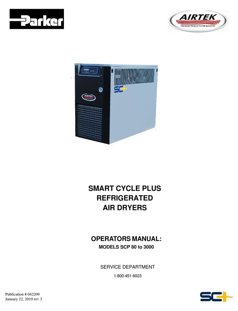
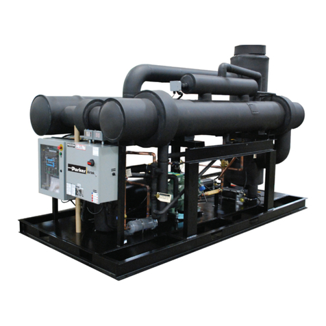
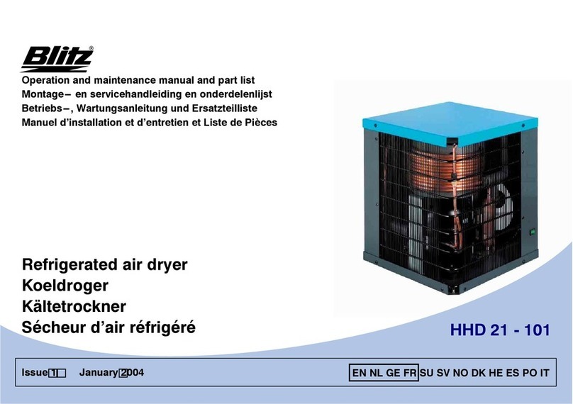
Parker Airtek MSC4000 User manual

Magnum Refrigerated Air Dryers
Models MSC4000 - MSC15000

2
MSC4000 - MSC15000 USER MANUAL
Introduction
These instructions must be thoroughly read and understood before installing and operating
this product. Failure to operate this product in accordance with the instructions set forth in
this manual can lead to unsafe operating conditions and may void warranty. For additional
information, refer to this manual or contact the factory for recommendations. Please have
the dryer serial number and model ready when contacting the factory.
Factory Contact Information
Phone 1-800-343-4048
For pricing, availability, and purchase orders: GSFOrders@parker.com
For technical support and aftermarket: GSFsupport@parker.com
For product applications and technical sales: FAFQuotes@parker.com

3
MSC4000 - MSC15000 USER MANUAL
1. Transporation/Inspection .................................................................................4
1.1 Environmental & Location Considerations ........................................................................................... 4
2. Dryer Installation ................................................................................................5
2.1 Plumbing the Air Lines .......................................................................................................................... 5
2.2 Electrical Connections........................................................................................................................... 5
2.3 Installation of Dewpoint Probe.............................................................................................................. 6
3. Start Up Procedure ...........................................................................................7
3.1 When Operating Dryer........................................................................................................................... 8
4. Controls/User Interface..................................................................................12
4.1 Main Display......................................................................................................................................... 12
User Controls....................................................................................................................................... 12
Status & State Messages .................................................................................................................... 13
Menu Icons .......................................................................................................................................... 15
4.2 Settings................................................................................................................................................ 16
User Settings....................................................................................................................................... 16
Drain Settings...................................................................................................................................... 17
Advanced Settings .............................................................................................................................. 18
User Sensor Settings .......................................................................................................................... 19
Sensor Calibration............................................................................................................................... 20
Pressure Sensors ................................................................................................................................ 20
Temperature Sensors .......................................................................................................................... 21
Factory Settings .................................................................................................................................. 22
Variable Speed Drive........................................................................................................................... 24
4.3 Trending ................................................................................................................................................ 25
Trend Elements.................................................................................................................................... 26
User Controls ...................................................................................................................................... 27
4.4 I/O Screens.......................................................................................................................................... 28
Input States ......................................................................................................................................... 28
Ouput States ....................................................................................................................................... 30
4.5 Sensors................................................................................................................................................ 31
4.6 Service Screen .................................................................................................................................... 32
Service Timer ...................................................................................................................................... 33
Real Time Clock.................................................................................................................................. 34
Reference Guide ................................................................................................................................. 35
4.7 Support Screen ................................................................................................................................... 39
4.8 Alarm Screens ..................................................................................................................................... 40
Alarm Information Screens.................................................................................................................. 43
4.9 Communications ................................................................................................................................. 52
4.10 Remote PLC Operation....................................................................................................................... 62
5. Routine Maintenance......................................................................................62
6. Maintenance Schedule ...................................................................................64
6.1 Maintenance Procedures .................................................................................................................... 64
7. Alarms / Troubleshooting / Service...............................................................65
7.1 General Service / Troubleshooting / Oil Management Mode ............................................................ 70
7.2 Refrigerant Charging Procedure ......................................................................................................... 70
8. Technical Data.................................................................................................72
9. Spare Parts Lists.............................................................................................76
10. Associated Drawings......................................................................................82
11. Maintenance Charts .....................................................................................106
12. Warranty.........................................................................................................107
Contents
4
MSC4000 - MSC15000 USER MANUAL
1. Transport / Inspection
Before unpacking/uncrating your new dryer, inspect the carton/crate for damage. Please note any damage
on the freight bill, and le notice of concealed damage if:
(a) there are any dents or visibly broken parts
(b) there is any sign of oil on the skid or oor
File these claims with the carrier immediately! Otherwise, proceed with unpacking/uncrating the unit.
1.1. Environmental & Location Considerations
Following these guidelines will help insure that your new dryer will provide safe and reliable service.
• Unless supplied for special conditions, all dryers must be located indoors in an area with an ambient
temperature between 41 - 100ºF (5-38ºC) and free from explosive and corrosive fumes. Three (3) feet
(92cm) of space must be allowed between all open grills, walls, or other objects.
• If the dryer is installed in a conned area, an exhaust system must be provided to eliminate re-circulation
of hot atmospheric air.
• With air cooled dryers, high ambient temperatures affect the outlet dewpoint of the dryer. The unit must
not operate in an ambient of over 115ºF (46ºC). If ambient temperature conditions are over 100ºF (38ºC),
water cooled dryers are generally recommended.
• Unit must be installed indoors.
• On water-cooled units, install a strainer. Maximum water inlet pressure is 150 PSIG (10.4 BarG). Dryers are
designed for 85ºF (29ºC) inlet water temperature. Higher water temperature reduces dryer capacity
(consult the factory for water temperatures above 85ºF (29ºC).
• Dryer must be installed on a at concrete pad rated for the total weight of the dryer.
Parameter Concentration
Langelier Index 0-1
pH 7.5 - 9
Sulfate (SO4
2-) <50 ppm
Electrical Conductivity 10-500 μS/cm
Ammonia (NH3) <1 ppm
Chloride (Cl-) < 50 ppm
Total Hardness 70 - 150 ppm CaCO3
Oxygen (O2) <0.1 ppm
Iron (Fe) <0.2 ppm
Nitrate (NO3
-) <2 ppm
Alkalinity (HCO3
-) 70 - 300 ppm
Hydrogen Sulde (H2S) <5 ppm
Free CO2<5 ppm
Aluminum (Al) <0.2 ppm
Cooling Water Quality to Condenser
(Water Cooled) Requirements
CAUTION

5
MSC4000 - MSC15000 USER MANUAL
2.1. Airline Plumbing
• Air piping must be supported independently of the dryer.
• If vibration is present, exible metal hoses (or other vibration dampening methods) must be
installed to prevent it from being transmitted to the dryer.
• Use unions or ange joints.
• Install a bypass line and gate valves to permit isolation of the dryer from the air system. This is
done to provide easy service and/or removal of the dryer without interruption of air to the system.
• Make the connection to the draining system, avoiding connection in a closed circuit shared by
other pressurized discharge lines. Check the correct ow of condensate discharges. Dispose of all
condensate in conformity with current local environment regulations.
• Direction of ow through the dryer must be observed. A check valve on the outlet of the dryer to
prevent back ow and false loading is recommended.
2.2. Electrical Connections
To be performed by a qualified person only. Risk of serious injury or death.
Observe Lock Out/Tag Out Procedure: Disconnect, lock out and tag all power at source prior to
attempting repairs or adjustments to rotating machinery and prior to handling any ungrounded conductors.
Provide breach and short circuit protection as well as disconnect means per local and national codes.
Before connecting electrical power to the dryer check for correct voltage at the connection box.
All units must be externally grounded to protect against severe electrical shock.
• Check for correct voltage and phase at electrical connection box.
• Install a fused disconnect switch near the dryer per the local codes.
• Connect power to the main lugs of dryer disconnect switch located in the high voltage enclosure.
• Make sure no bare wire is exposed; replace box cover and screw closed.
• Caution: Wire the dryer separately from the air compressor.
The dryer must NOT cycle on and off with the air compressor.
• Phase rotation is only important if the dryer has a 3-phase condenser fans (MSC4000-15000).
Fans must PULL air through the condenser coil.
• Crankcase heaters are pre-wired from the factory to the line side of the compressor contactor.
When power is applied to the dryer, the heater will energize. Heaters must be energized at all
times, therefore the main disconnect must be left on except when servicing the dryer. Heater must
be energized for 12 hours prior to start–up and after prolonged shut down 2 hours or more).
The power must be left on at all times except when servicing.
SHOCK
HAZARD
CAUTION
SHOCK
HAZARD
CAUTION
SHOCK
HAZARD
2. Dryer Installation
• Never work on unit under pressure!
• Never work on unit when power is connected.
• Do not over-pressurize unit.
• Install unit in a clean, cool (50º - 100ºF / 10º - 38ºC); well lighted location
• Do not shut unit off at disconnect switch except during service. Unit must be turned on and off by
the panel switch located on the dryer.
• Do not operate dryer at abnormal conditions (high ow, high inlet temperature, high ambient,
high inlet pressure, etc.)
CAUTION

6
MSC4000 - MSC15000 USER MANUAL
2.3. Installation of Dewpoint Probe
• Dryer will not run if Dewpoint Probe is not connected to the cable from the controller.
• Do NOT run the dryer without the probe installed as shown and described below!
• Install the probe into the evaporator.
• Do NOT bend!
• Install into the evaporator dully inserted past the tubesheet into one of the evaporator tubes.
• Note – When installing the probe, use a thread-lock sealant on the brass and steel threads.
• If probe is not installed correctly it WILL result in damage to the evaporator, consult factory if you are unsure.
PROBE GOES HERE AND MUST BE FULLY
INSERTED AS SHOWN PAST THE TUBESHEET
INTO AN EVAPORATOR TUBE.
NOT FULLY INSERTING THE PROBE WILL
RESULT IN SERIOUS PRODUCT FAILURE.
WRONG WAY - PROBE NOT FULLY INSTALLED
- WILL RESULT IN FAILURE!
WRONG WAY - DO NOT BEND PROBE TO INSTALL!
CORRECT INSTALLATION OF PROBE

7
MSC4000 - MSC15000 USER MANUAL
3. Start Up Procedure
Preliminary Checks
Before starting the dryer, verify that the compressed air valves are closed so there is no airow through the
dryer, the dryer supply voltage is correct, and there is sufcient water supply to the unit (water cooled). Also
ensure unit is level at this time.
Start-Up Procedure
There should be NO air ow through the dryer before or during start-up. It is recommended that the dryer
be installed with bypass piping to better service the unit. Inlet & outlet valves to the dryer should be closed
with the by-pass valve open.
1. Units are shipped with the refrigeration service valve tagged with a “VALVE CLOSED” label.
These tagged service valves must not be opened until the dryer is ready to be started and the
main power is permanently applied. Only tagged service valves must be opened.
2. Locate tagged service valves and remove end cap from valve stem.
3. Using a refrigeration service or small crescent wrench, turn the valve stem counterclockwise
until it stops. The valve will now be fully opened.
4. Before replacing the caps tighten the packing on all service valves (turn clockwise) if a leak is noticed.
Replace cap.
5. After electrical connection (Refer to Section 2.2), apply power.
6. After power has been applied the control panel should say “OFF” and the crankcase heater will now
start heating. THE CRANKCASE HEATER MUST BE SWITCHED ON 12 HOURS BEFORE STARTING
THE DRYER. Failure to comply with this may cause serious damage to the compressor.
7. Open the condenser water supply and return valves on water-cooled units.
8. If necessary, bleed the air from the condenser water shell.
START THE DRYER BEFORE SUPPLYING AIR!!!
CAUTION
1. Press the “RUN” button to start the dryer. (See description of “Oil Management Mode” in Section 7.1,
if the system goes into oil management mode upon start up)
2. Verify correct rotation of fans on air-cooled units. There is no rotation that needs to be checked on
water-cooled units.
3. Wait until the dryer reaches cycling temperatures and pressures.
4. Do not pass air through the dryer until it stabilizes and cycles off (cycles 2-3 times).
• Verify the liquid level in the surge tank sight glass for proper oil return! Adjustment is usually not required, and
the refrigerant level must be veried after 24 to 48 hours of operation. Adjust as necessary, using the Level
Master Control Valve (TXV). Counterclockwise raises the level & clockwise lowers the level. The oil level in the
refrigeration compressor should be between ¼ and ¾ in the compressor sight glass when the compressor
is loaded. Contact Customer Service if there are ANY questions. The refrigerant level will rise and fall during
normal operation.
CAUTION: If liquid level is not operating within this site glass, there will be insufcient oil return and will
cause refrigerant compressor damage or failure. If there is excessive liquid (overll) in the surge tank,
there could be liquid ood-back which could also cause refrigerant compressor damage or failure.
5. Once the dryer cycles off, you can now introduce compressed air to the dryer.
6. SLOWLY pressurize the dryer. Once completed slowly open the outlet valve, then close the bypass valve.
The dryer is now on line.
• Note: Fast opening of air valves could damage the heat exchangers. At this time, complete the following
start up form.
7. Clean the condensate drain Y-Strainer after the rst 8 hours of operation.
(See section 5.0 Routine Maintenance)
(continued on page 8)

8
MSC4000 - MSC15000 USER MANUAL
3.1. When Operating Dryer
1. Turn dryer On and Off at control panel only.
2. Keep power to unit at all times except when servicing.
3. Start dryer prior to allowing air ow through unit.
4. Clean condenser when necessary.
5. Maintain ambient temperature between 41-100ºF (5-38ºC)
6. Keep inlet temperature under 101ºF (38ºC)
7. Check and clean Y-strainer regularly.
8. NEVER allow dryer to cycle ON/OFF with air compressor.
8. Restart dryer using this procedure after maintenance, power outage or prolonged periods of shutdown
(2 hours or more).
• Note: The refrigerant compressor may require additional oil added. Oil level will need to be veried at
the same time as the expansion tank refrigerant level (within 24 to 48 hours) to ensure correct system
operation and adjustment.
For units supplied with Refrigeration Oil Separator (STD on Watercooled units – MSC4000 & UP and STD on
Aircooled MSC4000 & up)
• Change oil separator element 24-48 hours after initial start-up.
• An extra element for this change out is supplied with shipment.

9
MSC4000 - MSC15000 USER MANUAL
Start Up Checklist

10
MSC4000 - MSC15000 USER MANUAL
Comments / Recommendations / Observations
_______________________________________________________________
_______________________________________________________________
_______________________________________________________________
_______________________________________________________________
_______________________________________________________________
_______________________________________________________________
_______________________________________________________________
_______________________________________________________________
_______________________________________________________________
_______________________________________________________________
_______________________________________________________________
_______________________________________________________________
_______________________________________________________________
_______________________________________________________________
_______________________________________________________________
_______________________________________________________________
_______________________________________________________________
_______________________________________________________________
_______________________________________________________________
_______________________________________________________________
Completed By: (Print) ___________________________
Cert.# (REQUIRED)______________________________
Signature: _____________________________________
Customer Signature: ____________________________

11
MSC4000 - MSC15000 USER MANUAL

12
MSC4000 - MSC15000 USER MANUAL
4.1 Main Display
1. Menu Icon – Touch to display the menu icons on the sides of the display.
2. Snapshot Icon – Touch to save a snapshot of any screen to the ash drive.
3. Help Icon – Touch to display online help screens where available.
4. Run / Stop Keys
Run Key – Touch to start dryer if key is green.
Stop Key – Touch to stop dryer if key is red.
5. Mode Select Keys (Not included on dryers with variable drive or single mode dryers)
Auto-Mode Select – Touch to toggle auto select mode
Load/Unload Mode – Touch to switch to Load/Unload Mode
Cycling Mode – Touch to switch to Cycling Mode
6. Alarm Keys (M)
Alarm Reset Key – Touch to reset all active alarms.
Alarm Silence Key – Touch to silence the alarm screen and turn off the alarm relay.
7. Drain Test Key – Touch to test the drain valves.
8. Log In / Log Out Keys – Touch to log in and log out as required.
Supervisor default password is SUP (all caps)
The password may be changed by any person logging into the dryer. If the password is lost, however, the display
panel must be completely reprogrammed by a service representative.
1
2
3
8
5
4
6
User Controls
4. Controls / User Interface
7
MSupervisor level access required

13
MSC4000 - MSC15000 USER MANUAL
1. Status Message Line – Displays one or more of the following including any active alarms
ALL SYSTEMS OK – There are no active alarms
ALARM SHUTDOWN – An alarm condition has resulted in the dryer shutting down. Refer to Alarm screen for
assistance.
PUMPDOWN IN PROGRESS – The dryer will remove refrigerant from the suction lines while the dryer is off
so that is does not restart under excessive load.
OIL RECOVERY MANAGEMENT ACTIVE – In order to ensure enough oil is being returned to the
compressor under low load conditions, the compressor is forced to run at 100% output on a periodic
basis by temporarily increasing the dryer load.
HIGH HEAD PRESSURE LIMIT – The discharge pressure is running close to the alarm limits. To avoid
unnecessarily shutting down due to momentary high pressure, the dryer output will be reduced.
DRYER NOT CONFIGURED! – The dryer must be congured before it will run.
ACTIVE ALARMS – Refer to the Alarms Section for alarm messages displayed on this line.
2. State Message Line – Displays the current run mode of the dryer
DRYER OFF - PRESS RUN TO START
RESET ALARMS TO ENABLE RUN - The alarm must be reset by touching RESET ALARMS key before
the dryer is allowed to restart.
VARIABLE SPEED MODE – (VSD Dryers only) Currently running in variable speed mode.
The following modes are not included on dryers with variable drives.
LOAD/UNLOAD MODE – Currently running in Load/Unload mode.
LOAD/UNLOAD MODE – (AUTO SELECT) - Currently running in Load/Unload mode. The dryer will
switch to Cycling mode if the compressor runs unloaded for more than 5 minutes
CYCLING MODE – Currently running in Load/Unload mode.
CYCLING MODE – (AUTO SELECT) – Currently running in Cycling mode. The dryer will switch to Load/
Unload mode if the dryer cycles on less than 15 minutes after the compressor shuts off.
Status & State Messages
1
2

14
MSC4000 - MSC15000 USER MANUAL
Main Screen Indicators
Direct Drive Models (-A4, -W4)
1. Output Meter – Shows the dryer output in percent
2. Compressor Indicators
Compressor State – The compressor icon will turn on if the compressor(s) is running.
Compressor state indicators 1 through 4 – On dryers with more than one compressor use corresponding indi-
cators to determine which compressors are currently running.
Cylinder unloader state indicators A & B will turn on if the cylinders are loaded.
Unloader bypass valve indicator will turn on if the compressor is bypassed
3. Fan Indicators (Air Cooled Models only)
Fan State – The fan icon will turn on if any of the fans are running.
Multi-Fan indicators 1 through 3 – On dryers with more than 1 fan, use corresponding indicators to show which
fans are currently running.
4. Drains Indicators
Drain valve icon will turn on if the drain is open.
Drain switch indicator will turn on when the drain switch closes.
5. Suction Line Valve and Liquid Line States
6. Inlet and Outlet Pressure and Temperature
7. Suction Pressure and Temperature
8. Superheat Temperature
9. Discharge Pressure Sensor
10. Ambient Air/Water Temperature
11. Filter Differential Pressure
12. Dewpoint
13. User Sensors #1 and #2 (if enabled)
1
2
3
8
5
4
6
7
9
11
12
13
5
10

15
MSC4000 - MSC15000 USER MANUAL
Main Screen Indicators
Direct Drive Models (-A4, -W4)
7
Menu Icons
1. Trending Icon – Touch to access the trending screens
2. Alarms Icon – Touch to access the active alarms, alarm history, and alarm troubleshooting.
3. Sensors Icon – Touch to display real-time sensor values, including user sensors
4. I/O Screens Icon – Touch to access the states of the PLC Inputs and Outputs
5. Service Icons – Touch for access to service functions
6. Support Icon – Touch for access to dryer and support information
7. Hide Menu Icon – Touch to hide the menu icons
8. Settings Icon – Touch to access the setting screens
9. Page Left and Page Right Icons – Touch to step through the setting screens
10. Snapshot Icon – Touch this to save a snapshot of the entire display to the ash drive
11. Help Icon – Touch this to display help screens
1
2
38
5
4
6
9
11
10

16
MSC4000 - MSC15000 USER MANUAL
4.2 Settings
Dewpoint (M) – Set the target dew point from 36 to 50 degrees F.
High Inlet Temperature Warning (M)
Setting – Use to adjust the High Inlet Temperature Warning threshold
Enabled/Disabled – Touch to Disable or Enable the warning
Low Inlet Pressure Warning (M)
Setting – Touch to adjust the Low Inlet Pressure Warning threshold
Enabled/Disabled – Touch to Disable or Enable the warning
High Inlet Pressure Warning (M)
Setting – Touch to adjust the High Inlet Pressure Warning threshold
Enabled/Disabled – Touch to Disable or Enable the warning
High Filter Pressure Warning (M) – Touch to adjust the High Filter Pressure Warning threshold
Alarm Relay Operation (M) – Touch to toggle between normally open and normally closed relay operation.
Configure Alarm Relay (M) – Touch to enter Alarm Relay conguration screen (See alarms section)
Modbus RTU Slave ID(M) – Touch to set the Modbus RTU address of the HMI. Default is 61.
Note: If this setting is missing, then the address is set at 61 and cannot be changed.
User Settings
MSupervisor level access required

17
MSC4000 - MSC15000 USER MANUAL
Drain type (M)
Set to “None” if using pneumatic drains.
Set to “Level” if using solenoid demand oat drains.
Autotest Time (M) – Set the time (between 30 to 1440 minutes) between Autotest cycles for drains which use a drain
level switch. This will force the drain to open automatically regardless of whether the drain switch is closed or not.
Drain Cycle Interval (M) – Set the number of seconds between drain opening for drains which are running in Timed
Drain mode.
Drain On Duration (M) – Set the number of seconds that the drain will remain open per drain cycle while for drains
which are running in Timed Drain mode.
Note: Level drains which experience a drain fault will automatically switch to timed drain mode using the duration
and interval times. Clearing the alarm will switch the drain back to level drain mode.
Drain Settings
MSupervisor level access required

18
MSC4000 - MSC15000 USER MANUAL
Advanced Settings
Note: Changing these settings may negatively affect the performance of the dryer or disable key monitoring func-
tions. Be certain you understand the potential effects before changing these settings.
High Ambient/Water Temperature Alarm (M) – Touch to adjust the High Ambient or Water Temperature Alarm
threshold
Enable Oil Level Monitoring Alarm (M) – Touch to disable/enable the oil level monitoring system alarm
Enable Oil Recovery Management Function (M) – Touch to disable/enable the oil recovery function. This function
will periodically output the compressor at 100% to ensure that there is enough oil getting back to the compressor
under low load conditions.
Pressure Units (M) – Select units for pressure values used for all displays and logs.
Temperature Units (M) – Select units for temperature values used for all displays and logs.
The following are only included on dryers with more than one compressor:
Compressor Auto-Switch Time (M) – Touch to adjust the auto switch time for cycling the compressor. This ensures
that all compressors will be placed online at least once per 24 hours, thereby reducing balancing the wear across all
compressors.
Enable Compressor #1 through #4 (M) – Touch to disable/enable each compressor. This allows a compressor to
be taken ofine for service.
MSupervisor level access required

19
MSC4000 - MSC15000 USER MANUAL
There are two 4-20mA inputs on the PLC for the user.
Sensor Input 1 is settable from -32768 to 32767 with a resolution of one unit.
Sensor Input 2 is settable from -3276.8 to 3276.7 with a resolution of one tenth of a unit.
Sensor Description (M) – touch to open the on screen keyboard in order to enter a short description of the sensor
(maximum 8 characters)
Sensor Input Enable (M) – touch to enable the sensor input and all associated functions
Sensor Units (M) – touch to open the on screen keyboard in order to enter a units of the sensor
(maximum 4 characters)
Sensor Range (M) – Enter the minimum and maximum limits of the sensor range -32768 to 32767 units for sensor
one, -3276.8 to 3276.7 units for sensor one
Offset Correction (M) – Enter an offset value for the sensor range.
Alarm Settings (M) – The following alarm settings are available for both low and high alarm thresholds
for each sensor input.
• Setpoint – enter alarm threshold
• Enable – touch to enable or disable the alarm
• Alarm timeout – enter the number of seconds for the condition to be true before the alarm will occur
• Auto Reset – touch to enable the alarm to automatically reset when the condition is no longer true.
Otherwise the alarm must be manually reset from the main screen.
User Sensor Settings
MSupervisor level access required

20
MSC4000 - MSC15000 USER MANUAL
Pressure Sensors
The following settings apply to each pressure sensor.
Sensor Range (S) – Enter the minimum and maximum limits of the sensor range.
Offset Correction (S) – Enter an offset value for the sensor range.
Pressure Units (M) – Select units for pressure values used for all displays and logs.
Sensor Calibration
MSupervisor level access required
SService level access required
This manual suits for next models
30
Table of contents
Other Parker Dehumidifier manuals

Parker
Parker CDAS HL 050 Series Manual

Parker
Parker Airtek SMART CYCLE PLUS 80 User manual

Parker
Parker Airtek TW 10 Instruction manual

Parker
Parker K-MT 1-8 User manual

Parker
Parker Airtek MSC Series User manual

Parker
Parker Domnick Hunter PNEUDRI DME012 User manual

Parker
Parker DME012-RX User manual

Parker
Parker DTX 10 User manual

Parker
Parker HDK-CNG Series User manual

Parker
Parker CDAS HL 050 Series User manual