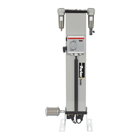
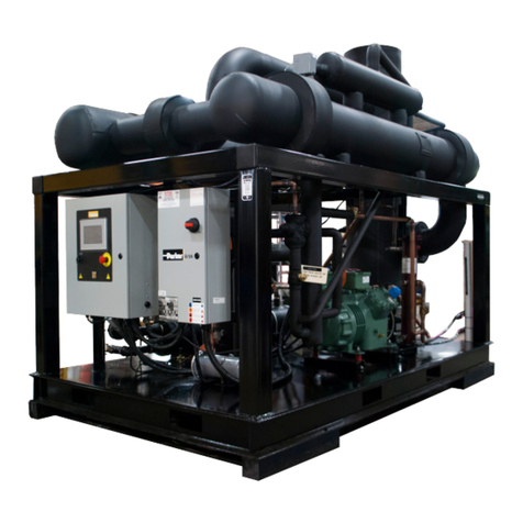
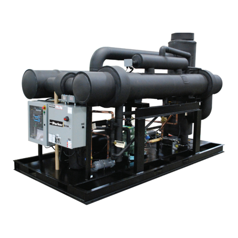
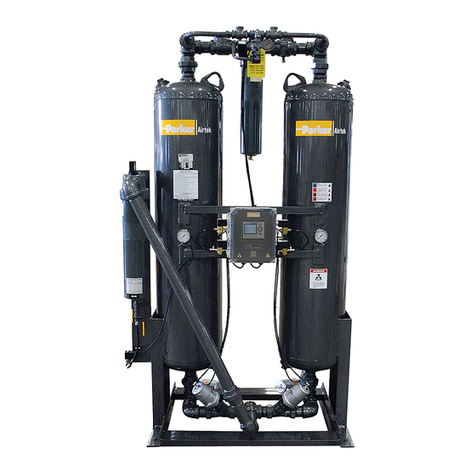
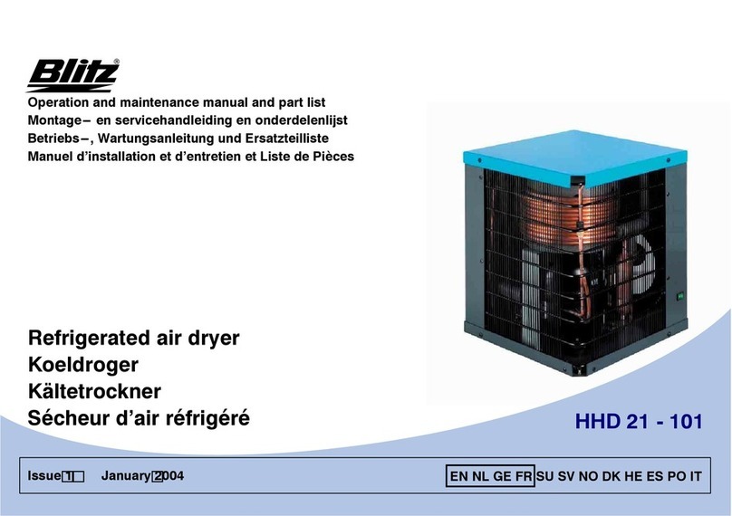
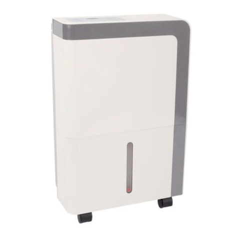
Parker Airtek SMART CYCLE PLUS 80 User manual

- 1 -
SMART CYCLE PLUS
REFRIGERATED
AIR DRYERS
OPERATORS MANUAL:
MODELS SCP 80 to 3000
SERVICE DEPARTMENT
1-800-451-6023
Publication # 042209
January 22, 2010 rev 3

- 2 -
Table of Contents
Section 1.0 - EQUIPMENT DATA SHEET - Page 4
Section 2.0 - GETTING STARTED - Page 5
Section 3.0 - DRYER INSTALLATION - Page 6
Section 4.0 - CONTROLS - Page 11
Section 5.0 - START UP PROCEDURE - Page 17
Section 6.0 - ROUNTINE MAINTENANCE - Page 20
Section 7.0 - DIAGNOSTIC CODES - Page 21
Section 8.0 - MAINTENANCE CHARTS - Page 25
Section 9.0 - ASSOCIATED DRAWINGS - Page 27 – 44
Section 10.0 - WARRANTY/PRODUCT
REGISTRATION - Page 45

- 3 -
Air Dryer as Built Specifications
Serial No. Model:
DESCRIPTION VALUE UNIT
---------------Dryer Design Max Air Flow SCFM Comments:
-
----------------Dryer Design Max Air PSI PSI/BAR
-
-----Dryer Design Max Inlet Temperature ºF/ºC REFRIGERANT
-
-------------------------Supply Voltage VOLT CHARGE: Lbs.
-
----------------------------------Cycle HZ TYPE:
----------------------------------Phase PH FLA: N/A
-
-----------------Number of Compressors RLA: amps
-
----------------Compressor Horse Power HP LRA: amps
-
---------------MinimumCircuit Ampacity AMPS
----------------(copper) THHN Wire Size AWG #
-
--------------Fuse / Circuit Breaker Size AMP REPLACEMENT
-
----------------------Nema Starter Size PART# ELEMENT:
QTY:
-----------------------Crankcase Heate
r
WATTS
---------------Crankcase Heater Voltage VOLT
-------------------------Number of Fans
-
-----------------Fan Motor Horse Powe
r
HP
-
-------------------------Max Amp Draw AMPS
----------------(copper) THHN Wire Size AWG #
-
------------------------------Fuse Size AMP
e
nter n/a if not used) Nema Starter Size PART #
-
-----------------------Overload Setting AMPS
-Water Condenser Max Inlet Temperature ºF
-Water Condenser Minimum Inlet Pressure PSI
-----------Control Transformer VA Rating VA
-
-----Control Transformer Primary Voltage VOLT
-
---Control Transformer Primary Fuse Size AMP Electrical Dwg No.'s
-
--Control Transformer Secondary Voltage VOLTS
-
Control Transformer Secondary Fuse Size AMP
-
-------------Refrigerant Low PSI Setting PSI/BAR
-------------Refrigerant High PSI Setting PSI/BAR
-
---------------Fan Bank #1 PSI Settings PSI/BAR
-
---------------Fan Bank #2 PSI Settings PSI/BAR
---------------Refrigerant Oil PSI Setting PSI/BAR
Section 1.0 – EQUIPMENT DATA SHEET
- 4 -
Section 2.0 - Getting Started
Before unpacking/uncrating your new dryer, inspect the carton/crate for damage. Note any damage on the
freight bill. File notice of concealed damage if:
(a) there are any dents in the cabinets
(b) the air and drain pipes are not straight
(c) there is any sign of oil on the skid or floor
(d) the refrigerant gauges show NO pressure
File these claims with the carrier immediately!
Otherwise, proceed with unpacking/uncrating the unit.
Environmental & Location Considerations
Following these guidelines will help insure that your new dryer will provide safe and reliable service.
Unless supplied for special conditions, air cooled dryers must be located in an area with an ambient
temperature between 50…100ºF (10…35ºC) and free from explosive and corrosive fumes. Three
(3) feet (92cm) of space must be allowed between all open grills, walls, or other objects.
Dryers for below freezing (31º, -0.5ºC) ambient temperatures are available with an optional
additional refrigeration condenser bypass valve.
If the dryer is installed in a confined area, an exhaust system must be provided to eliminate
recirculation of hot atmospheric air.
High ambient temperatures affect the outlet dew point of the dryer. For every 10º of ambient
temperature over 100ºF (35ºC) a decrease of 9% of dryer performance is encountered with air cooled
dryers. The unit must not operate in an ambient of over 115ºF (46ºC). If ambient temperature
conditions are over 100ºF (35º), water cooled dryers are recommended.
CAUTION
!

- 5 -
Section 3.0 – DRYER INSTALLATION
NEVER work on unit under pressure
NEVER work on unit when power is connected.
DO NOT over pressurize unit.
DO NOT pass air through the unit until it has been stabilized (operating 2 - 15 minutes).
The larger the dryer, the longer it takes to stabilize. Let unit cycle 2 – 3 times to stabilize.
Plumbing the Air Lines
The dryers are shipped ready to run. All connections are made to the outside of the cabinet.
Air piping must be supported independently of the dryer.
Direction of the air flow must be observed for proper installation. (Fig. 1)
General Layout
For Connections
(all connections are labeled)
H20 In/Out
(if water cooled)
Drain
Use unions or flange joints on inlet and outlet pipe connections. (Fig. 2)
If vibration is present, flexible metal hoses must be installed to prevent the vibration from being
transmitted to the dryer.
Install a bypass line and gate valve to permit isolation of the dryer from the air system. This is
done to provide easy service and/or removal of the dryer without interruption of air to the system.
CAUTION
!
Fig. 1

- 6 -
Fig. 2
(Models 80- 300)

- 7 -
USE TWO (2) WRENCHES WHEN CONNECTING DRYER TO PIPING. THIS WILL
PREVENT DAMAGE TO INTERNAL AIR LINES.
Recommended tools for Start-up
1. Roto-lock packing wrench (special)
2. Refridge service wrench
3. Small adjustable wrench
4. 6” adjustable wrench
5. Philips screw driver
6. Nut driver for panel removal
1
2
3
4
5
6
Attention
!

- 8 -
ELectrical Connection
Service Switch (On Models SMART CYCLE PLUS 300 to 3,000)
1. Remove side cover and locate electrical box.
2. Remove electric box cover from inside unit.
3. Locate the wires.
4. Locate hole on side of box, place and tighten connector, run wires through connector.
5. Using wire connectors, connect Black to Hot wire, White to Neutral and Green to Ground wire.
Refer to table above for voltage and wire colors.
6. Make sure no bare wire is exposed; replace box cover and screw closed.
7. Turn Service Switch “ON”.
8. Replace side covers.
Electrical Hook-up
Voltage Phase Wire Colors
115V Single Black, White, Green
230V Single Black, Red, Green
230V 3 Phase 3 Black, 1 Green
460V 3 Phase 3 Black, 1 Green
575V 3 Phase 3 Black, 1 Green
To be performed by a qualified person only.
Risk of serious injury or death. Before
connecting electrical power to the dryer check
for correct voltage and phase at the connection
box. All units must be externally grounded to
protect against sever electrical shock.
Toggle Switch shown in the “OFF” position as
shipped. Switch must remain in the “OFF”
position until ALL electrical wiring has been
completed.

- 9 -
Wire the dryer separately from the air compressor. The dryer must not cycle with the air
compressor. Refer to Section 6.0 – Start up Procedure.
Phase rotation is important if the dryer has a 3 phase condenser fan and/or the unit is
equipped with a scroll compressor (SMART CYCLE PLUS 500 – 1200). Fans must pull air
through condenser coil.
Read special TAG on scroll compressors fro proper rotation.
Observe dewpoint reading to verify rotation. If dewpoint reading does not drop within 30
seconds, turn unit off and reverse two electrical leads.
Crankcase heaters are pre-wired at the factory to line side of terminal box or contactor.
Heaters must be energized at all times, therefore the main disconnect must be left on at all
times except when servicing.
CAUTION
!

- 10 -
Section 4.0 - Controls
REFRIGERANT DRYER CONTROLLER
FEATURES AND OPERATIONS
(1) – RUN SELECT KEY: (MODE SELECTOR)
Push Key to toggle through the four modes of operation (‘AUTO’ Run Mode, ‘LOAD/UNLOAD’ Mode,
‘CYCLING’ Mode, and ‘OFF’). The Display ‘main screen’ will indicate all modes of operation along with the
current Dew Point measurement.
(2) – ALARM KEY: (RESET ALARMS)
When the ALARM Key red ‘LED’ is flashing, the system has experienced an alarm event. The Display will
indicate all alarms when they occur. Pushing the ALARM Key will attempt to clear the fault. Note with some
alarms, the system will need to be restarted.
(3) – DRAIN KEY: (OPERATE DRAIN)
When the ‘DRAIN’ Key is pressed, the drain solenoids will operate for the programmed time duration. (see
Settings, Drains). The green LED will illuminate indicating the drains are open.
(4) – LOAD KEY: (VIEW LOAD %)
Pushing the ‘LOAD’ Key will toggle the Display between indicating ‘Mode & Dew Point’ (standard), and,
‘Percent of Load’ (optionally) that the dryer is experiencing. The green LED will illuminate indicating the
display option is active.

- 11 -
5) – READ KEY: (MEASUREMENT READINGS)
The ‘READ’ Key will scroll through each system measurement.
(6) – SETTINGS KEY: (PROCESS VALUES)
The ‘SETTINGS’ Key will scroll through each user setting (process value). The amber LED will illuminate
indicating the display is active.
(7) – YES / UP KEY: (YES & UP)
When the ‘YES / UP’ Key is pressed, the controller will either increment up or toggle depending on which
user setting is selected in the ‘SETTINGS menu. Note the SETTINGS Key amber LED will now flash. To
save the ‘new’ process value setting, press the SETTINGS Key again – a message ‘ARE YOU SURE?’ will
display (answer either YES or NO, the LED will stop flashing.
(8) – NO / DOWN KEY: (NO & DOWN)
When the ‘NO / DOWN’ Key is pressed, the controller will either decrement up or toggle depending on which
user setting is selected in the ‘SETTINGS menu. Note the SETTINGS Key amber LED will now flash. To
save the ‘new’ process value setting, press the SETTINGS Key again – a message ‘ARE YOU SURE?’ will
display (answer either YES or NO, the LED will stop flashing.
(9) – MULTI COLORS INDICATOR:
These LED’s will illuminate in RED, AMBER and GREEN. They represent a ‘visual’ indication as to dryer
loading. If all the LED’s are RED, this is the worst possible state (a combination of very bad dew point and or
overloaded. The other side of the spectrum would be only one GREEN LED illuminated; indicating less then
(<10%) ten percent capacity is being utilized and all is OK.
(10) – MAINTENANCE MONITOR:
The controller will remind the user to perform maintenance on the dryer every six month. The Display will
indicate (and the ALARM LED will flash), the statement “CHANGE FILTER.” IMPORTANT – The user
should change the coalescing filter on a regular basis. Also do all other recommended maintenance (see
maintenance section of the Operating Manual) at this time.
To reset the ‘Maintenance Monitor’ at the completion of the maintenance procedures, push the ALARM Key
and when the “HAS FILTER BEEN CHANGED? (YES / NO)” message is in the Display, press the ‘YES’ Key.
Pressing the YES Key will reset the Change Filter timing for six months. Selecting the ‘NO’ key will exit the
menu and the message will repair again in 8 hours.
OTHER FEATURES:
On ‘power-up’ the Display will indicate the system configuration (System Operating Code #, CFM Range and
Firmware Revision) for three seconds.

- 12 -
(11) Air Inlet & Outlet PSI Gauges. Indicates that unit is pressurized. Unit MUST be depressurized and
bypassed before any service work is done on air system. Excessive pressure drop (more than 5 PSIG)
across dryer indicates water may be freezing in the evaporator.
11
Dual Pressure Gage –
Upgrade on certain models

- 13 -
DP5550 Displays
Power On Screen – Displayed for 3 seconds after power-on or reset
Model and Size
Firmware Rev/Date
Main Display - System OFF
Main Display - System Running, No Alarms
Press the RUN SELECT key to cycle thru the operating modes
Operating Mode
Operating Dew Point
Operating Modes
“SYSTEM OFF”
“AUTO MODE (L)” (L) = load/Unload Mode,
(C) = Cycling Mode
“LOAD/UNLOAD MODE”
“CYCLING MODE”
Main Display - System Running, with Warning Alarms
Alarm Description(s)
Operating Dew Point
Warning Alarms
"HIGH DEW POINT"
"DRAIN FAULT"
"HIGH CONDENSER TEMP."
"HIGH INLET TEMP"
"HIGH DIFF PRESSURE"
"BAD SENSOR WARNING"
"CHANGE FILTER"
Note: if more than one alarm condition exists, then the top line of the display will automatically cycle
thru all active alarms.
[4] 1500-3000 CFM
1.0.4.9x/Dec 1 2009
SYSTEM OFF
Press Run Select
AUTO MODE (L)
DEW POINT:36°F
HIGH INLET TEMP
DEW POINT:36°F

- 14 -
Main Display - System Shutdown Due To Critical Alarm
Alarm Description
Shutdown status
Critical Alarms
"DRYER OVERLOAD"
"BAD SENSOR SHUTDOWN"
"LOW SUCTION PRESSURE"
"HIGH DISCHARGE PRES."
"HIGH SUPERHEAT"
"EVAPORATOR FROZEN"
"EMERGENCY STOP"
"BAD PUMPDOWN"
"SYSTEM FAULT"
Press the ALARM key to reset all alarms
Press the RUN SELECT key to restart the dryer after an alarm
Note: if more than one alarm condition exists, then the top line of the display will automatically cycle
thru all active alarms.
Read System Parameters
Press the READ key to cycle thru the system parameter values
Parameter Description
Parameter Value
Dew Point Temp. 0 thru 200 oF
Superheat Temp. 0 thru 100°F
Suction Temperature 0 thru 200 oF
Suction Pressure 0 thru 600 psi
Discharge Pressure 0 thru 600 psi
Inlet Temperature 0 thru 200 oF
Condenser Temperature 0 thru 200 oF
Note: The parameter value will display “FAULT!” if the sensor input is invalid
Dew point
36°F
HIGH DISCHARGE PRES.
Alarm Shutdown
AUTO MODE (L)
Alarm Shutdown

- 15 -
Settings Menu - User Settings
Press the SETTINGS key to cycle thru the user settings
Setting Description
Setting
User Settings
Default Settings
TARGET DEW POINT? 38 oF 36 thru 50 oF DRAIN
DURATION? 2 secs 1 thru 30 seconds
DRAIN CYCLE? 60 mins 0 thru 60 minutes
MAX CONDENSER TEMP? 100°F 0 thru 125°F
MAX INLET TEMP? 101°F 0 thru 125°F
TEMPERATURE UNITS? °F °F, °C
PRESSURE UNITS? psi psi, kPa, bars
NETWORK ADDRESS? 1 1 thru 247
Changing the User Settings
Setting Description
Setting,
Use the UP and DOWN keys to change the setting
Press the SETTINGS key when finished
Select YES or NO to confirm
YES selected, store setting
NO selected, restore previous setting
TARGET DEW POINT?
36°F
TARGET DEW POINT?
36°F
TARGET DEW POINT?
ARE YOU SURE?
New Setting Saved
Setting NOT Saved!

- 16 -
Load Display
Press the LOAD key to display the dryer load percentage
Clearing the Maintenance Timer
Press the ALARM RESET key to reset the maintenance timer and alarm
Press YES to reset the timer to 6 months (after maintenance has been performed)
Press NO to reset the timer to 8 hours (until maintenance has been performed)
Dryer Load
67%
HAS FILTER BEEN
REPLACED? (YES/NO)

- 17 -
Section 5.0 – START UP PROCEDURE
There should be NO air flow through the dryer before or during start up. It is recommended that the
dryer be installed with bypass piping to better service the unit.
Smart Cycle Plus 80-100
1. Plug in unit.
2. Switch unit on. On / Off switch will light green when unit is running.
3. Unit is ready for operation.
Smart Cycle Plus 130 – 3000
1. After electrical connection (Refer to Section 3), apply power.
2. Leave power on for 8 hours before proceeding any further. (Both green load – unload thermal
bank LED’s should be OFF on the control panel).
3. Remove side panel from unit.
4. Some units are shipped with the refrigeration service valve tagged. These tagged service valves
must not be opened until the dryer is ready to be started and the main power is permanently
applied. Only tagged service valves must be opened.
5. Locate tagged service valves and remove end cap from valve stem. (Fig. 3 below)
CAUTION
!

- 18 -
6. Using a refrigeration service or small crescent wrench, turn the valve stem counterclockwise until
it stops. Occasionally it may be necessary to re-tighten the packing nut (turn clockwise) if a leak
is noticed. The valve will now be fully opened. (Fig. 3)
7. Replace cap.
8. Switch unit on by selecting the Load-Unload button. On / Off green LED indicator will light when
unit is running.
9. If the storage conditions were adverse (for example very cooled) the refrigeration compressor
may make a loud metallic hammering noise. If this happens, turn the dryer off at the panel and
wait 60 seconds. Then turn the dryer back on. Repeat this procedure until the refrigeration
compressor runs smoothly. The dewpoint should start to drop towards the set point.
Valve Cap
(Turn CCW to remove) Valve Stem
(Turn CCW to open)
Packing Nut (CW)
Tighten after opening
Closed Position Open Position
Figure 3

- 19 -
Do not pass air through the dryer until it is stabilized.
(Unit cycles 2 – 3 times)
10. With the dryer turned on from the control panel, and is stabilized, you can now introduce
compressed air to the dryer.
11. Check the automatic drain for proper operation. Drain should open at regular intervals based on
the drain control settings.
Clean Y-Strainer after the first 4 hours of operation. (If unit has float demand
drains there is no Y-Strainer, for larger unit only not 80 – 1200 SCFM)
12. Restart dryer using this procedure after maintenance, power outage or prolonged periods of
shutdown.
When Operating Dryer
1. Turn dryer On and Off at control panel.
2. Keep power to unit during off cycles.
3. Start dryer prior to allowing air flow through unit.
4. Clean condenser when necessary.
5. Keep ambient temperature under 95ºF (35ºC)
6. Keep inlet temperature under 100ºF (37.7ºC)
7. Keep inlet pressure above 100 PSI (8.6 bars)
8. Check and clean Y-strainer often (shut isolation valve off).
9. NEVER cycle dryer with air compressor.
Attention
!

- 20 -
Section 6.0 – ROUTINE MAINTENANCE
Routine Maintenance
The air cooled condenser on your dryer must be kept clean. Inspect on a regular basis for dirt or debris that
might accumulate. Remove any debris immediately.
It is recommended that the drain and solenoid be checked weekly for proper functioning. The Y-strainer
should be checked and screen cleaned monthly.
(Fig. 4)
It is not advisable to tamper with the other adjustments unless you are familiar with
refrigeration. The controls interact with each other and, although the effect of an adjustment
may not be immediately obvious, it will affect the dryer’s performance.
C
CH
HA
AR
RG
GE
E
L
LI
IQ
QU
UI
ID
D
R
RE
EF
FR
RI
IG
GE
ER
RA
AN
NT
T
O
ON
NL
LY
Y,
,
D
DO
O
N
NO
OT
T
C
CH
HA
AR
RG
GE
E
W
WI
IT
TH
H
V
VA
AP
PO
OR
R!
!
S
Se
ee
e
t
ta
ag
g
f
fo
or
r
c
co
or
rr
re
ec
ct
t
r
re
ef
fr
ri
ig
ge
er
ra
an
nt
t
c
ch
ha
ar
rg
ge
e.
.
U
Un
ni
it
t
n
ne
ee
ed
ds
s
t
to
o
b
be
e
p
pu
ul
ll
le
ed
d
i
in
nt
to
o
v
va
ac
cu
uu
um
m
5
50
00
0
m
mi
ic
cr
ro
on
n
(
(m
mi
in
ni
im
mu
um
m)
)
T
Th
he
e
f
fu
ul
ll
l
c
ch
ha
ar
rg
ge
e
m
mi
ig
gh
ht
t
n
no
ot
t
b
be
e
a
ac
cc
ce
ep
pt
te
ed
d.
.
I
If
f
t
th
hi
is
s
o
oc
cc
cu
ur
rs
s,
,
t
th
he
e
u
un
ni
it
t
c
ca
an
n
b
be
e
s
st
ta
ar
rt
te
ed
d
a
an
nd
d
t
th
he
en
n
t
th
he
e
r
re
em
ma
ai
in
nd
de
er
r
o
of
f
t
th
he
e
c
ch
ha
ar
rg
ge
e
s
sh
ho
ou
ul
ld
d
b
be
e
s
sl
lo
ow
wl
ly
y
m
me
et
te
er
re
ed
d
i
in
nt
to
o
t
th
he
e
s
su
uc
ct
ti
io
on
n
s
si
id
de
e
(
(S
Su
uc
ct
ti
io
on
n
s
si
id
de
e
i
is
s
a
al
lw
wa
ay
ys
s
t
th
he
e
i
in
nl
le
et
t
t
to
o
c
co
om
mp
pr
re
es
ss
so
or
r
s
si
id
de
e)
).
.
Screen
Valve
(Turn CCW to close)
Cap with O-ring
Y-Strainer
Closed
Y-Strainer
Open
CAUTION
!
Attention
!
This manual suits for next models
3
Table of contents
Other Parker Dehumidifier manuals

Parker
Parker CDAS HL 050 Series User manual

Parker
Parker Domnick Hunter PNEUDRI DME012 User manual

Parker
Parker HDK-CNG Series User manual

Parker
Parker DME012-RX User manual

Parker
Parker Airtek MSC4000 User manual

Parker
Parker K-MT 1-8 User manual

Parker
Parker CDAS HL 050 Series Manual

Parker
Parker Airtek TW 10 Instruction manual

Parker
Parker Airtek MSC Series User manual

Parker
Parker DTX 10 User manual