Parker 2003-PB-00 User manual

DOC-0017-10-EN: AC20 Series PROFINET IO Option
1 (47) DOC-0017-10-EN-B 04.04.2023
DOC-0017-10-EN-B
04.04.2023
AC20 Series
PROFINET IO– Communication Option
Technical Manual

DOC-0017-10-EN: AC20 Series PROFINET IO Option
2 (47) DOC-0017-10-EN-B 04.04.2023
1 Safety
IMPORTANT: Please read this information BEFORE installing the equipment.
1.1 Intended Users
This manual is to be made available to all persons who are required to install, configure or service equipment
described herein, or any other associated operation.
The information given is intended to highlight safety issues, and to enable the user to obtain maximum benefit
from the equipment.
Complete the following table for future reference detailing how the unit is to be installed and used.
INSTALLATION DETAILS
Model Number
(see product label)
Where installed
(for your own
information)
1.2 Application Area
The equipment described is intended for industrial motor speed control utilizing AC induction motors or AC
permanent magnet synchronous machines.
1.3 Personnel
Installation, operation, and maintenance of the equipment should be carried out by competent personnel. A
competent person is someone that is technically qualified and familiar with all safety information and
established safety practices; with the installation process, operation, and maintenance of this equipment,
and with all the hazards involved.
1.4 Product Warnings
Special attention must be paid to the information presented in warning, caution, and information notices
when they appear in this manual. Definitions of caution, warning and information notices are shown below:
Application Risk
The specifications, processes and circuitry described herein are for guidance only and may need to be
adapted to the user’s specific application. We cannot guarantee the suitability of the equipment described in
this Manual for individual applications.

DOC-0017-10-EN: AC20 Series PROFINET IO Option
DOC-0017-10-EN-B 04.04.2023 3 (47)
Risk Assessment
Under fault conditions, power loss or unintended operating conditions, the drive may not operate as
intended. In particular:
•Stored energy might not discharge to safe levels as quickly as suggested and can still be present
even though the drive appears to be switched off.
•The motor's direction of rotation might not be controlled
•The motor speed might not be controlled
•The motor might be energised
A drive is a component within a drive system that may influence its operation or effects under a fault
condition. Consideration must be given to:
•Stored energy
•Supply disconnects
•Sequencing logic
•Unintended operation
1.5 Safety Information
Risk of Electric Shock
DANGER!
Ignoring the following may result in injury:
- This equipment can endanger life by exposure to rotating
machinery and high voltages.
- The equipment must be permanently earthed due to the high
earth leakage current, and the inverter motor must be connected
to an appropriate safety earth.
- Ensure all incoming supplies are isolated before working on the
equipment. Be aware that there may be more than one supply
connection to the inverter.
- There may still be dangerous voltages present at power terminals
(motor output, supply input phases, DC bus and the brake, where
fitted) when the motor is at standstill or is stopped.
- For measurements use only a meter to IEC 61010 (CAT III or
higher). Always begin using the highest range.
CAT I and CAT II meters must not be used on this product.
- Allow at least 5 minutes for the inverter's capacitors to discharge
to safe voltage levels (<50V). Use the specified meter capable of
measuring up to 1000V dc & ac rms to confirm that less than 50V
is present between all power terminals and between power
terminals and earth.
- Unless otherwise stated, this product must NOT be dismantled. In
the event of a fault the inverter must be returned. Refer to
"Routine Maintenance and Repair".

DOC-0017-10-EN: AC20 Series PROFINET IO Option
4 (47) DOC-0017-10-EN-B 04.04.2023
Safety & EMC Requirements
Where there is a conflict between safety and EMC requirements, personnel safety shall always take
precedence.
WARNING!
Ignoring the following may result in injury or
damage to equipment:
- Never perform high voltage resistance checks on the wiring
without first disconnecting the inverter from the circuit being
tested.
- Whilst ensuring ventilation is sufficient, provide guarding and /or
additional safety systems to prevent injury or damage to
equipment.
- When replacing an inverter in an application and before returning
to use, it is essential that all user defined parameters for the
product’s operation are correctly installed.
- When replacing an inverter in an application and before returning
to use, it is essential that all user defined parameters for the
product’s operation are correctly installed.
- All control and signal terminals are SELV, i.e. protected by double
insulation. Ensure all external wiring is rated for the highest
system voltage.
- Thermal sensors contained within the motor must have at least
basic insulation.
- All exposed metalwork in the Inverter is protected by basic
insulation and bonded to a safety earth.
- RCDs are not recommended for use with this product but, where
their use is mandatory, only Type B RCDs should be used.
WARNING!
Ignoring the following may result in injury or
damage to equipment:
- In a domestic environment this product may cause radio
interference in which case supplementary mitigation measures
may be required.
- This equipment contains electrostatic discharge (ESD) sensitive
parts. Observe static control precautions when handling,
installing and servicing this product.
- This is a product of the restricted sales distribution class
according to IEC 61800-3. It is designated as “professional
equipment” as defined in EN61000-3-2 for. Permission of the
supply authority shall be obtained before connection to the public
low voltage supply.

DOC-0017-10-EN: AC20 Series PROFINET IO Option
DOC-0017-10-EN-B 04.04.2023 5 (47)
2 Manufacturing Location
Germany
Parker Hannifin Manufacturing Germany GmbH & Co. KG
Electric Motion & Pneumatic Division (EMPD)
Robert-Bosch-Strasse 22
77656 Offenburg (Germany)
Tel.: + 49 (0781) 509-0
Website: www.parker.com/eme
Certified according to ISO 9001:2015
Parker Hannifin Manufacturing Germany GmbH & Co. KG - Sitz: Bielefeld - Amtsgericht: Bielefeld HRA 15699
persönlich haftende Gesellschafterin: Parker Hannifin GmbH - Sitz: Bielefeld - Amtsgericht Bielefeld HRB 35489
Geschäftsführung der Parker Hannifin GmbH: Ulrich Jochem, Achim Kohler, Andreas Paulsen, Kirsten Stenvers
Vorsitzender des Aufsichtsrates: Dr.-Ing. Gerd Scheffel

DOC-0017-10-EN: AC20 Series PROFINET IO Option
6 (47) DOC-0017-10-EN-B 04.04.2023
3 Waste Electrical and Electronic Equipment (WEEE)
Waste Electrical and Electronic Equipment - must not be disposed of with domestic
waste. It must be separately collected according to local legislation and
applicable laws.
Parker Hannifin Company, together with local distributors and in accordance with EU directive 2002/96/EC,
undertakes to withdraw and dispose of its products, fully respecting environmental considerations.
For more information about how to recycle your Parker supplied waste equipment, please contact your local
Parker Service Centre.
Packaging
During transport our products are protected by suitable packaging. This should be taken for central disposal
as secondary raw material.

DOC-0017-10-EN: AC20 Series PROFINET IO Option
DOC-0017-10-EN-B 04.04.2023 7 (47)
4 Table of Contents
1Safety.................................................................................................................................................... 2
1.1 Intended Users............................................................................................................................ 2
1.2 Application Area .......................................................................................................................... 2
1.3 Personnel .................................................................................................................................... 2
1.4 Product Warnings........................................................................................................................ 2
1.5 Safety Information ....................................................................................................................... 3
2Manufacturing Location...................................................................................................................... 5
3Waste Electrical and Electronic Equipment (WEEE) ....................................................................... 6
4Table of Contents ................................................................................................................................ 7
5Introduction.......................................................................................................................................... 8
5.1 Product Features......................................................................................................................... 8
6Installation............................................................................................................................................ 9
6.1 Order Codes................................................................................................................................ 9
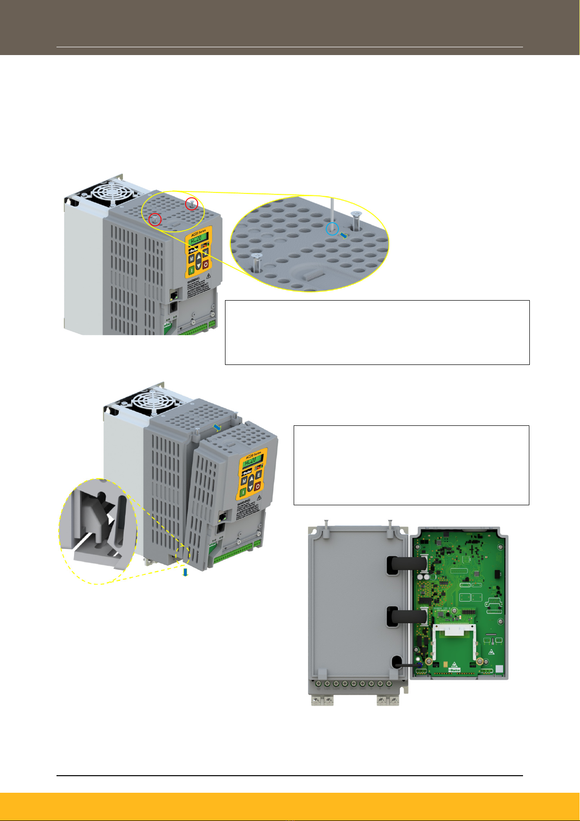
6.2 Fitting the Option....................................................................................................................... 10
7Network .............................................................................................................................................. 13
7.1 Network Connector and Cable Specification ............................................................................ 13
7.2 LED Indications ......................................................................................................................... 13
8Configuration..................................................................................................................................... 15
8.1 Communication parameters...................................................................................................... 15
8.2 Process Data............................................................................................................................. 18
8.3 Acyclic Data Exchange ............................................................................................................. 20
8.4 PROFINET GSDML File ........................................................................................................... 20
9Example Configuration and Programming ..................................................................................... 21
9.1 AC20 Motor Control Application................................................................................................ 21
9.2 List of process data................................................................................................................... 22
9.3 Programming with Siemens PLC .............................................................................................. 22
10 Option Module Webserver................................................................................................................ 34
11 FTP Server.......................................................................................................................................... 37
12 Lost Communication Trip................................................................................................................. 38
13 Diagnostic Event ............................................................................................................................... 39
APPENDIX A: Data types ............................................................................................................................ 40
APPENDIX B: Parameters........................................................................................................................... 41
APPENDIX C: Setting IP-Address via Anybus IPCONFIG ....................................................................... 44
APPENDIX D: DSE Lite Quick Start Guide ................................................................................................ 45

DOC-0017-10-EN: AC20 Series PROFINET IO Option
8 (47) DOC-0017-10-EN-B 04.04.2023
5 Introduction
5.1 Product Features
•Slave PROFINET Protocol
•Up to 64 modules, 8 submodules each (up to 128 submodules in total)
•Up to 1440 bytes I/O data in each direction status bytes included.
•Supports 250 μs cycle time.
•2 x RJ-45 PROFINET ports available simultaneously
•100 Mbit/s, full duplex
•Galvanically isolated 2-port Ethernet interface
•IIoT (Industrial Internet of Things) ready: Includes Email Client, Web server with customizable
content, SSI functionality and FTP server
•GSDML file provided
•LEDs to indicate network status (NS), Module status (MS) and Link activity (L/A)

DOC-0017-10-EN: AC20 Series PROFINET IO Option
DOC-0017-10-EN-B 04.04.2023 9 (47)
6 Installation
DANGER!
RISK OF ELECTRIC SHOCK
Terminal covers, main covers, and cover fixings must remain in place
while the drive is energized.
These should only be removed once the supply to the unit and/or system
has been disconnected, and the residual energy in the DC link capacitors
has been discharged.
CAUTION!
ESD SENSITIVE EQUIPMENT
Take ESD precautions when handling the Communication Interface
Option Cards to avoid any risk of damaging the equipment.
•All activities covered in this chapter should be carried out when there is no power to the inverter.
•If the drive has been powered up, ensure enough time has elapsed that the inverter has discharged
its residual energy.
•Always check that the voltages on the user terminals are at a safe level (<50V) before carrying out
any of these activities.
6.1 Order Codes
Order Code Description
2003-CB-00 CANopen communication interface option card
2003-EC-00 EtherCAT communication interface option card
2003-IP-00 Ethernet IP communication interface option card
2003-PB-00 Profibus DP-V1 communication interface option card
2003-PN-00 PROFINET IO communication interface option card
2003-RS-00 RS485 Modbus RTU communication interface option card

DOC-0017-10-EN: AC20 Series PROFINET IO Option
10 (47) DOC-0017-10-EN-B 04.04.2023
6.2 Fitting the Option
Frames 2 – 5
The Communication Interface Option Cards are intended to be customer installed.
The control module housing cover will need to be removed prior to option card installation.
1. Use a T9 TORX driver to partially unscrew the two 3x12
countersunk fixings along the top of the product.
2. Insert a flat head screwdriver into the moulding features and
lever the control module housing away from the power
tk
3. Unhook the bottom of the control module
housing from the power stack.
4. Gently turn the control module upside down
so it rests to the right of the power stack,
with the interface cables still connected.

DOC-0017-10-EN: AC20 Series PROFINET IO Option
DOC-0017-10-EN-B 04.04.2023 11 (47)
In the event that the Communication Interface Option Card needs to be removed, follow the installation
process, but perform steps 7 and 8 in reverse.
5. Remove and discard the Comms Option
break-out feature in the control module
housing by cutting the 7x bridges using
suitable small side cutters.
6. Remove the Comms Interface Option card from
its packaging.
7. Slide the Comms Card along the PCB using the
connector features for alignment.
Note: The front facia of the Option should be
loose at this point.
9. Now fully tighten the two T8 screws on the front
facia of the Communication Interface Option
Card.
10. Check that the Option Card is secure and that it
cannot slide out.
11. Reassemble the product by performing the
reverse process of steps 1 – 4.

DOC-0017-10-EN: AC20 Series PROFINET IO Option
12 (47) DOC-0017-10-EN-B 04.04.2023
Frame 6 – 10
On Frames 6 – 10, the lower terminal cover will need to be removed prior to option card installation.
In the event that the Communication Interface Option Card needs to be removed, perform steps 2 & 3 in
reverse.
1. Remove the Comms Interface Option card from its
packaging.
2. Slide the Comms Card along the PCB using the
connector features for alignment.
Note: The front facia of the Option should be loose
at this point.
3. When the Comms Interface Option Card is fully
engaged in the connector and its housing has
hocked onto the edge of the PCB, fully tighten
the two T8 screws on the front facia.
4. Check that the Option Card is secure and that
it cannot slide out.

DOC-0017-10-EN: AC20 Series PROFINET IO Option
DOC-0017-10-EN-B 04.04.2023 13 (47)
7 Network
7.1 Network Connector and Cable Specification
Two RJ45 Ethernet sockets are provided. Either or both sockets may be used. Having 2 ports reduces the
need for additional Ethernet switches.
Pin
Signal
4,5,7,8
Connected to chassis ground over serial RC circuit
6
RD-
3
RD+
2
TD-
1
TD+
Housing
Cable Shield
Only use cables terminated with RJ45 plugs.
7.2 LED Indications
LED
Description
1
Network Status
2
Module Status
3
Link/Activity (Port 1)
4
Link/Activity (Port 2)

DOC-0017-10-EN: AC20 Series PROFINET IO Option
14 (47) DOC-0017-10-EN-B 04.04.2023
Network Status (NS) LED
LED Status
Description
Comments
OFF
Offline
•No Power
•No Connection with IO Controller
GREEN (Solid)
Online (RUN)
•Connection with IO Controller Established
•IO Controller in RUN state
GREEN, 1 Flash
Online (STOP)
•Connection with IO Controller Established
•IO Controller in STOP state or IO Bad Data
•IRT Synchronization Not Finished
GREEN, Blinking
Blink
•Used by Engineering Tools to Identify the Ethernet
Node on the Network
RED (Solid)
Fatal Event
•Major Internal Error (this indication is combined
with a RED Module Status LED)
RED, 1 Flash
Station Name Error
•Station Name Not Set
RED, 2 Flashes
IP-Address Error
•IP-Address Not Set
RED, 3 Flashes
Configuration Error
•Expected Identification Differs from Real
Identification
Module Status (MS) LED
LED Status
Description
Comments
Off
Not Initialized
•No power or Module in SETUP or NW_INIT state.
Green
Normal Operation
•Module has shifted from the NW_INIT state
Green, 1 flash
Diagnostic Event(s)
•Diagnostic event(s) present
Red
Exception error
•Device in state Exception.
Alternating
RED/GREEN
Fatal event
•Major internal error (this indication is combined
with a red network status LED)
Link/Activity (L/A) LED
LED Status
Description
Comments
Off
No Link
•No Link, No Communication present.
Green (Solid)
Link
•Ethernet Link Established, No Communication
present
Green, Flickering
Network Activity
•Ethernet Link Established, Communication
Present

DOC-0017-10-EN: AC20 Series PROFINET IO Option
DOC-0017-10-EN-B 04.04.2023 15 (47)
8 Configuration
The option comms configuration is accessible through the keypad under the menu Option Comms,
through DSE Lite function block Option Comms Config or through the webserver following the path Home
> Engineer > Communications > Option Comms.
The AC20 PROFINET option requires configuration of both communication parameters and process data
mapping.
8.1 Communication parameters
Keypad Menu Path
DSE-Lite Function Block
Webserver
The network parameters of the slave must be set to establish communication with master.
•The parameter 0691 COMMS REQUIRED must be set to PROFINET.
•The parameter 0758 ADDRESS ASSIGNMENT slects the slave IP Addressing method.
•There are three methods to set the IP address, subnet mask and gateway address of the device:
the slave sets its own address, the address is set externally by a PROFINET master, or the
address is set by a DHCP server.
•If the IP address is set by the slave (Address Assignment = FIXED) then three further parameters
must be set:
0759 SET IP ADDRESS
0760 SET SUBNET MASK
0761 SET GATEWAY ADDRESS
•The parameter 0779 STATION NAME must be set from a PROFINET master.
•The parameter 2566 MASTERMAPPING must be set to choose how process data mapping will be
defined. (See Process Data Mapping for detail)
•The parameter 0762 ACCESS may be set to enable web features of the AC20 option comms (IP
Config Enable, Web Enable, Web Parameters Enable, FTP Enable, FTP Admin Mode).
Setup
Communication
Option

DOC-0017-10-EN: AC20 Series PROFINET IO Option
16 (47) DOC-0017-10-EN-B 04.04.2023
Configuration with DSE Lite
When performing an online configuration, the fitted option card will automatically be selected.
In offline mode, display your configuration page in DSE Lite and click the plus sign [+] at the left of function
block Option Comms Config to see set communication parameters.
Alternatively. perform the steps described above by double clicking on the function block Option comms
config to open parameters tab in the configuration interface.

DOC-0017-10-EN: AC20 Series PROFINET IO Option
DOC-0017-10-EN-B 04.04.2023 17 (47)
Configuration with the webserver
Access the AC20 webserver by typing the IP-Address of the drive into the web browser.
The drive must be in configuration state. Set the PROFINET Option comms parameters as shown below.
AC20 Webserver view when Master mapping is TRUE
AC20 Webserver view when Master mapping is FALSE
Device Name
The AC20 option comms slave requires a device (station) name to be assigned. This must be done by the
PROFINET master.

DOC-0017-10-EN: AC20 Series PROFINET IO Option
18 (47) DOC-0017-10-EN-B 04.04.2023
8.2 Process Data
AC20 parameters implementation
The AC20 PROFINET option requires configuration of process data mapping.
Config Mapping
There are two methods to define process data mapping: the process data will be mapped using the AC20
input and output mapping tables or from the PLC.
The parameter 2566 MASTERMAPPING defined the method; If FALSE the AC20 input and output
mapping tables will be used to configure process data mapping, If TRUE the bus master set/configures the
Process data mapping and AC20 input and output mapping tables will be cleared.
Set process data using AC20 input and output mapping tables
These tables are two parameter arrays in which AC20 parameter numbers may be added. The parameter
2566 MASTERMAPPING must be set to FALSE. The tables can be accessed via Keypad, via DSE Lite
application and via webserver.
Read Mapping:
The read process data represents cyclic data sent from the PLC to the AC20, this is mapped into the table
Option Comms Input Mapping. Only writable AC20 parameters that are not configuration parameters may
be added to the read process data.
Keypad Menu Path
DSE Lite Function
Block
Webserver
Engineer
Communications
Option Comms
Input Mapping[ ]

DOC-0017-10-EN: AC20 Series PROFINET IO Option
DOC-0017-10-EN-B 04.04.2023 19 (47)
Write Mapping:
The write process data represents cyclic data sent from the AC20 to the PLC, this is mapped into the table
Option Comms Output Mapping.
Keypad Menu Path
DSE Lite Function Block
Webserver
Note: String-type parameters cannot be mapped.
Set process data from PROFINET master
The GSDML file defines a number of modules. Each module corresponds to an AC20 parameter, when
configuring the PLC, the modules may be added to the slave device slots as required. These modules map
to the process data in the order in which they are added.
The parameter 2566 MASTERMAPPING must be set to TRUE and this will auto reset the AC20 input and
output mapping.
Cyclic Data Exchange
Cyclic data exchange will occur when a connection is established either in RUN mode (PROCESS
ACTIVE) or STOP mode (IDLE). However, the read process data will only update the mapped parameters
when in the PROCESS ACTIVE mode.
On a transition into the PROCESS ACTIVE state all read process mapped parameters will be updated.
When in the PROCESS ACTIVE state, the read process mapped parameters will all update only when a
change in the read process data occurs.
Mapping status
The process data mapping status can be accessed from AC20 via the following parameters:
•Parameter 2586 InMappingStatus: shows the status of the currently active cyclic data input
mapping table (32 entries), value is the Tag ID of the parameter to be cyclic read In.
•Parameters 2619 OutMappingStatus: Shows the status of the currently active cyclic data output
mapping table (32 entries), value is the Tag ID of the parameter to be cyclic sent out.
The parameters 2586 InMappingStatus and 2619 OutMappingStatus are visible from the webserver and
are valid if Parameter 0774 Comms State = PROCESS ACTIVE and parameter 2566 MasterMapping =
TRUE.
Engineer
Communications
Option Comms
Output Mapping[ ]

DOC-0017-10-EN: AC20 Series PROFINET IO Option
20 (47) DOC-0017-10-EN-B 04.04.2023
8.3 Acyclic Data Exchange
AC20 parameters may be accessed acyclically from the network using Record Data read / write services. If
addressed through a given API (Application Process Instance) and Index range, the module translates the
service into standard object requests towards the Application Data Object.
The AC20 parameters may be accessed via Application Process Instance zero (API 0). Slot 0, Subslot 1
may be used.
•There is a 1:1 correlation between the index and the parameter number.
•Parameter arrays may be accessed, either as a whole or as individual elements.
•Index 0 (zero) is not associated with a parameter and cannot be used
8.4 PROFINET GSDML File
The GSDML device description file holds a description of the device and its functions. Must important the
file describes the parameters implementation in the module. GSDML file for the AC20 PROFINET option
may be downloaded from the AC20 product page at www.parker.com
This manual suits for next models
11
Table of contents
Popular Server manuals by other brands

HIK VISION
HIK VISION DS-TP50-12DT user manual

Planet
Planet 1-Bay SATA NAS Server NAS-7100 Quick installation guide

Blackbe;rry
Blackbe;rry ENTERPRISE SERVER FOR IBM LOTUS DOMINO - - MAINTENANCE RELEASE... release note

Black Box
Black Box LES431A user manual

Sferalabs
Sferalabs Strato Pi Base user guide

Data Video
Data Video NVS-20 instruction manual