5 Parker Hannifin
Pump and Motor Division
Trollhättan, Sweden
Service Manual
Series F01
Bulletin HY30-5502-M1/UK
Operation Check
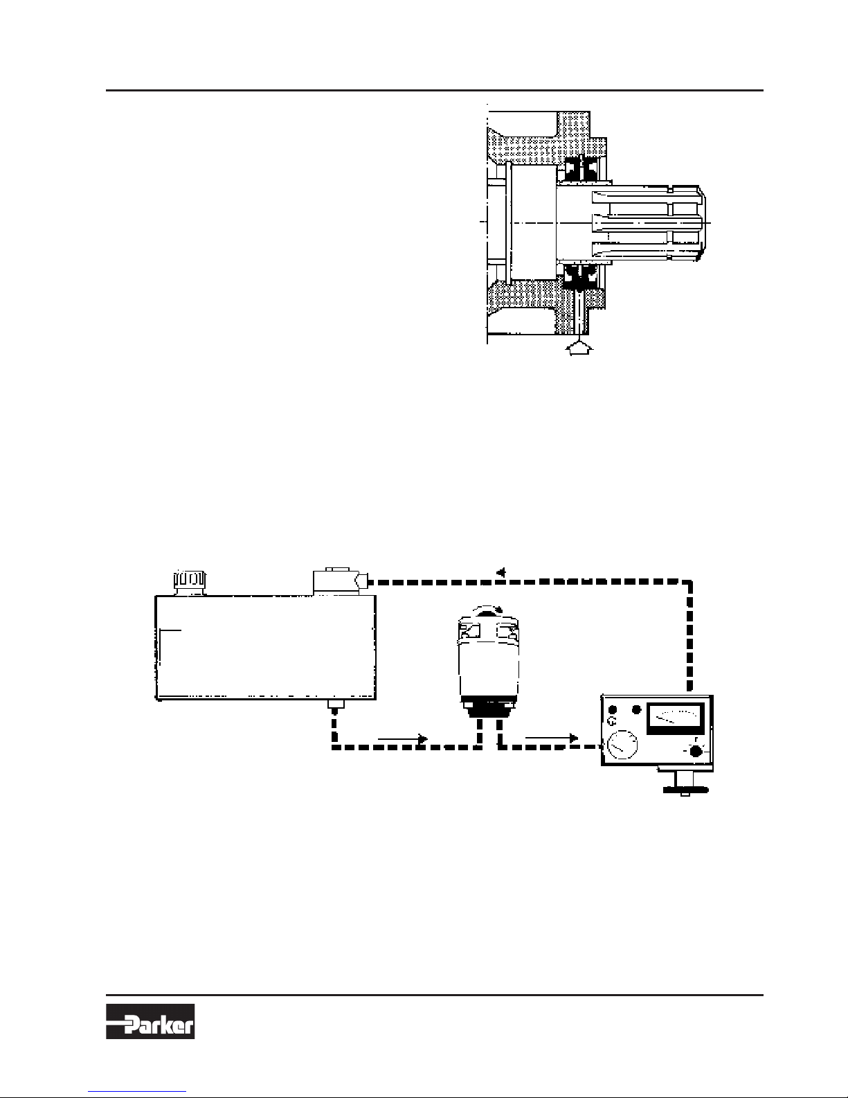
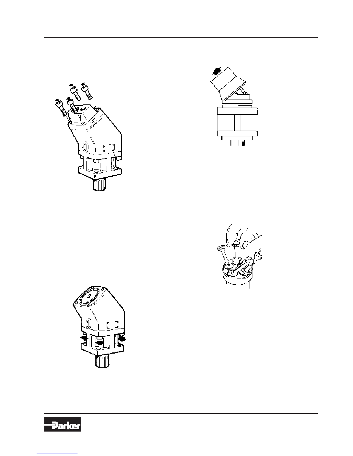
Check of Shaft Seal
The pump has two shaft seals - the inner one sealing the
hydraulic oil in the housing, and the outer one the trans-
misson oil when the pump is fitted to a PTO. If any of the
sealrings leak, the oil will come out through an indication
hole.
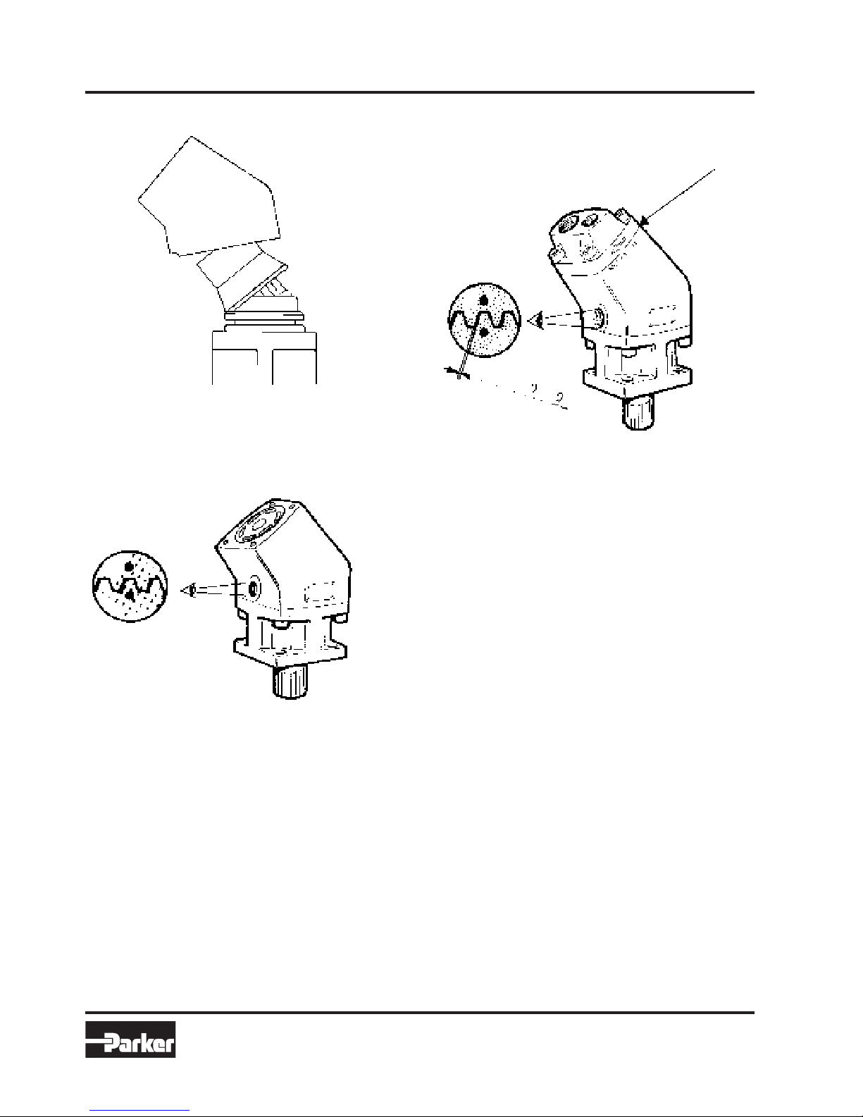
Indication hole
Note: A heavy leakage can be caused by a worn-out
pump, whereby high pressure oil will come out into the
housing in such large quantities that the sealring might
be damaged. If there is a steady stream of oil from the
indication hole, the pump is probably damaged and will
have to be replaced.
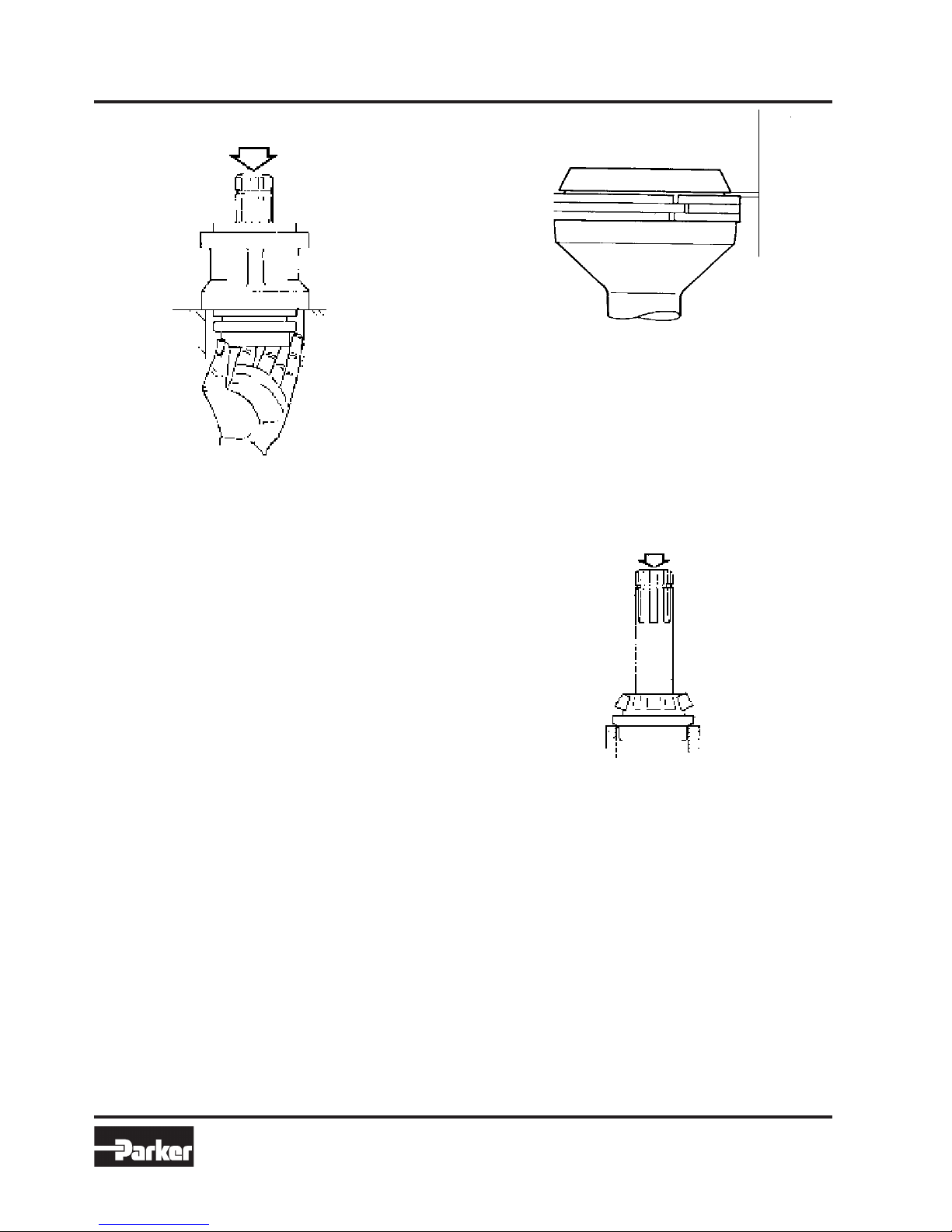
Check that no oil is dripping out of the indication hole,
when the pump is in operation. If there is a leakage from
the sealrings, they must be exchanged, See chapter ”Ex-
change of shaft seals”.
Checking the Flow from the Pump
The flow from the pump can be checked by means of a
test instrument comprising a flowmeter and a relief valve.
Connecton of test instrument
When the pump is running at about 800 - 1400 r.p.m. and
is loaded up to 150 - 200 bar, the flow must not decrease
by more than 10%.
Example:
An F1-40 running at 1225 r.p.m. gives - according to the
flowmeter. - a flow of 48 l/min.
If the pump is loaded, the flow must not decrease by
more than 0,1 x 48 = 4,8 l / min, i.e. the flowmeter should
indicated at least 48 - 4,8 = 43,2 l / min. If the flow drops
below this limit, the pump is worn out and will have to be


 Operator's manual")


