10 GB / IE / NI
Filling the oil mist unit
Ensure that the maintenance unit
has been separated from the
compressed air source before filling
or releasing the container 11.
Remove the oil container 11 by pressing
the release knob 10 and simultaneously
turning the oil container 11 (see Fig. E).
Fill the oil container 11 using suitable
compressor oil until the max. mark has
been reached (see Fig. B).
Subsequently tighten the container 11
only manually (without tools).
E
Starting up
Ensure that the connected com-
pressed air line is clean and oil-free
in order to properly use the
compressed air maintenance unit. Further
ensure that the pneumatic system is depres-
surised. To minimise pressure loss, it is
beneficial if the compressed air lines are
kept as short as possible.
Connect the pneumatic maintenance unit
to the compressed air source
First release the lock by mpulling the
pressure regular 3upwards. (see Fig. F)
Turn counter-clockwise to set the com-
pressed air controller 3to the lowest
possible level. The desired settings will
be assumed by pushing down the com-
pressed air controller 3.
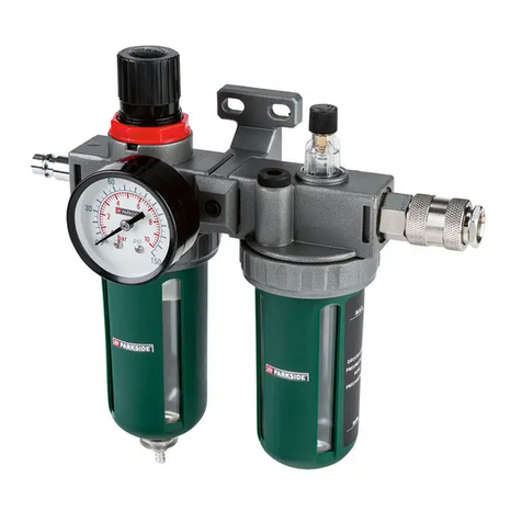
Connect the compressed air supply line
at the quick coupling 8of the tool to
be connected to the right side (output) of
the maintenance unit (see figure on the
right). A triangle "" on the surface of
the device indicates the flow direction of
the compressed air.
Connect the compressed air supply of
the compressed air source at the barbed
fitting 2on the left (input) of the main-
tenance unit (directly at the input, the
surface has a triangle "", that indicates
the flow direction of the compressed air).
F
Before commissioning of the mainte-
nance unit, check the compressed air
flow direction with the mark " " on the
surface. If the setting is not correct, the
pressure generated will not be correct.
Setting the working
pressure
After linking the maintenance unit to a
compressed air source (see above), you can
set the desired operating pressure with the
pressure controller 3.
First release the lock by pulling the
compressed air controller 3upwards.
(see Fig. F)
Turning counter-clockwise reduces the
pressure, and turning clockwise increas-
es the pressure.
Read the set pressure at the pressure
Installation / Starting up


