Installation instructions
INST REF:IN274-3
DATE: 09/07/19
Installation Instructions
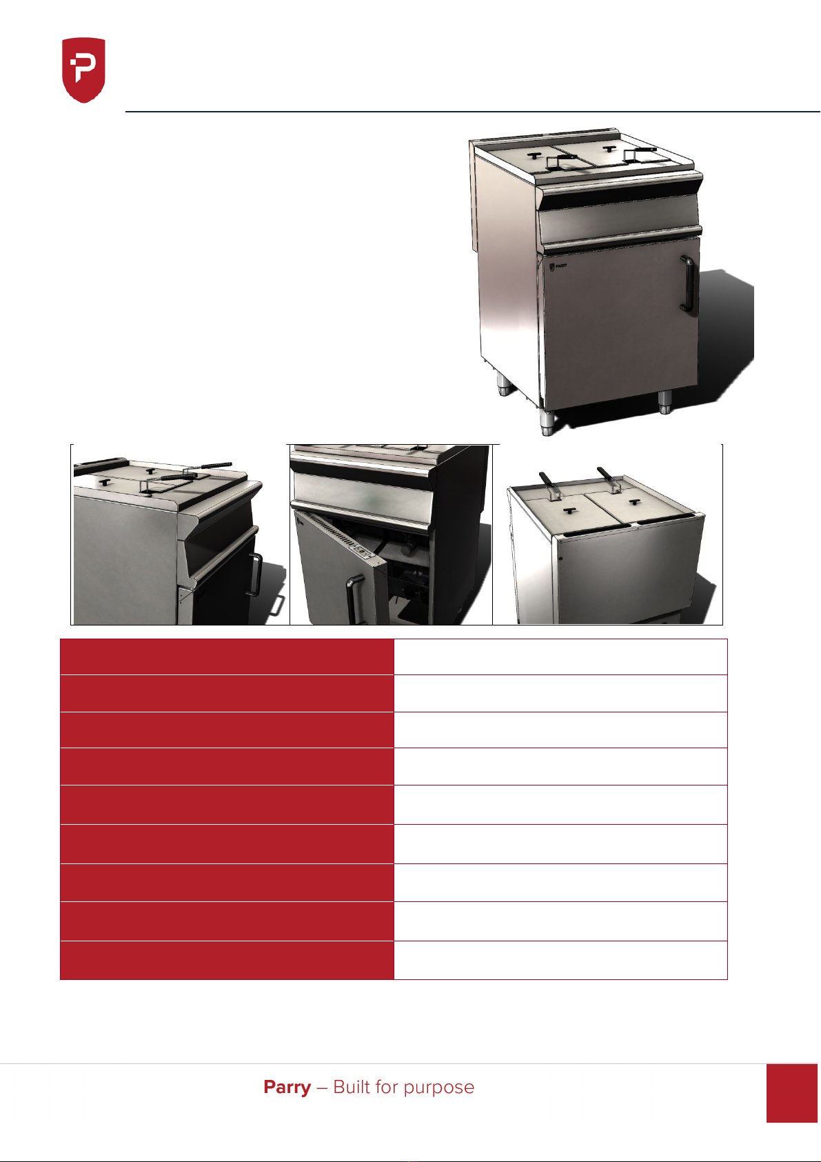
POSITIONING
The appliance must not be installed on or against combustible surfaces – minimum
clearances must be:
Rear 150mm (6”)
Sides 150mm (6”) FROM ANY ADJACENT WALL
It is recommended that the appliance be sited below a ventilating hood preferably of the
extractor type incorporating a grease filter.
The minimum distance between the top of the appliance and any over shelf or ceiling
constructed of combustible material must be 1525mm (60”). All local fire regulations
must be observed before the appliance is commissioned the gas safety regulations
require that all gas connections on the gas line are tested for gas soundness between
the gas meter and the appliance. All packing and protective film must be removed from
the panels etc. prior to commissioning the appliance.
GAS CONNECTION
The gas connection is ½” B.S.P.T. on the left hand side rear of the fryer. The supply
pipe must not be less than ½”, an easily accessible isolation cock should be fitted in the
pipework as close as possible to the fryer. An approved flex may be used in conjunction
with a straining cable.
Gas hoses used to connect the appliance to the gas supply must be of the correct
specification for the gas and pressure of the appliance. The gas hose must comply with
the national requirements in force, and be CE marked, of a metal braided construction
suitable for commercial catering equipment. The hoses should be periodically examined
and replaced as necessary
The tube or hose shall be fitted such that there are no sharp bends or torsional strain
which may cause damage or failure of the tube or hose, especially near the end fittings.
Torsional strain can be prevented by the use of internal unions, swivel joints, etc. The
bend radius should not exceed that stated by the Manufacturer. The hose should not
touch the ground and should be no longer than 1.5m long.
A manual valve should be positioned upstream of the tube or hose unless the
connection fitting incorporates a self-sealing quick release coupling.
Where a quick release coupling is used for horizontal travel such as in commercial
catering appliances it is advisable that the coupling is facing downwards to prevent the
ingress of debris and ensure the hose is formed in to a smooth curve.
All units should have a restraining cable fitted preventing the unit from being pulled
away from the wall and causing the gas hose to become disconnected accident.