ParTech ASLD2200 User manual

INSTRUCTION MANUAL
ASLD2200 Monitor
Sludge Blanket Level Monitor

** Thi page i intentionally left blank **

ASLD2200 - In truction Manual
Table of Contents
1 Introduction.................................................................................................................................................................. 5
1.1 General............................................................................................................................................................. 5
1.2 Output Signal.................................................................................................................................................... 5
1.3 Limit Relay........................................................................................................................................................ 5
1.4 Manual Convention ......................................................................................................................................... 5
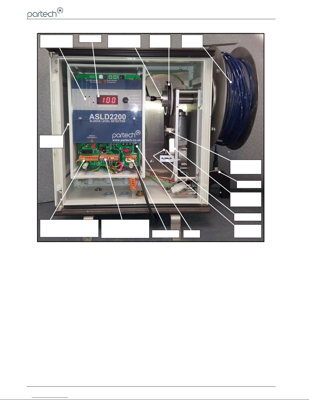
1.5 Mechanical Overview........................................................................................................................................ 6
2 Principle of Operation................................................................................................................................................... 7
3 ASLD2200 Selection.................................................................................................................................................... 8
3.1 Sen or Selection............................................................................................................................................... 8
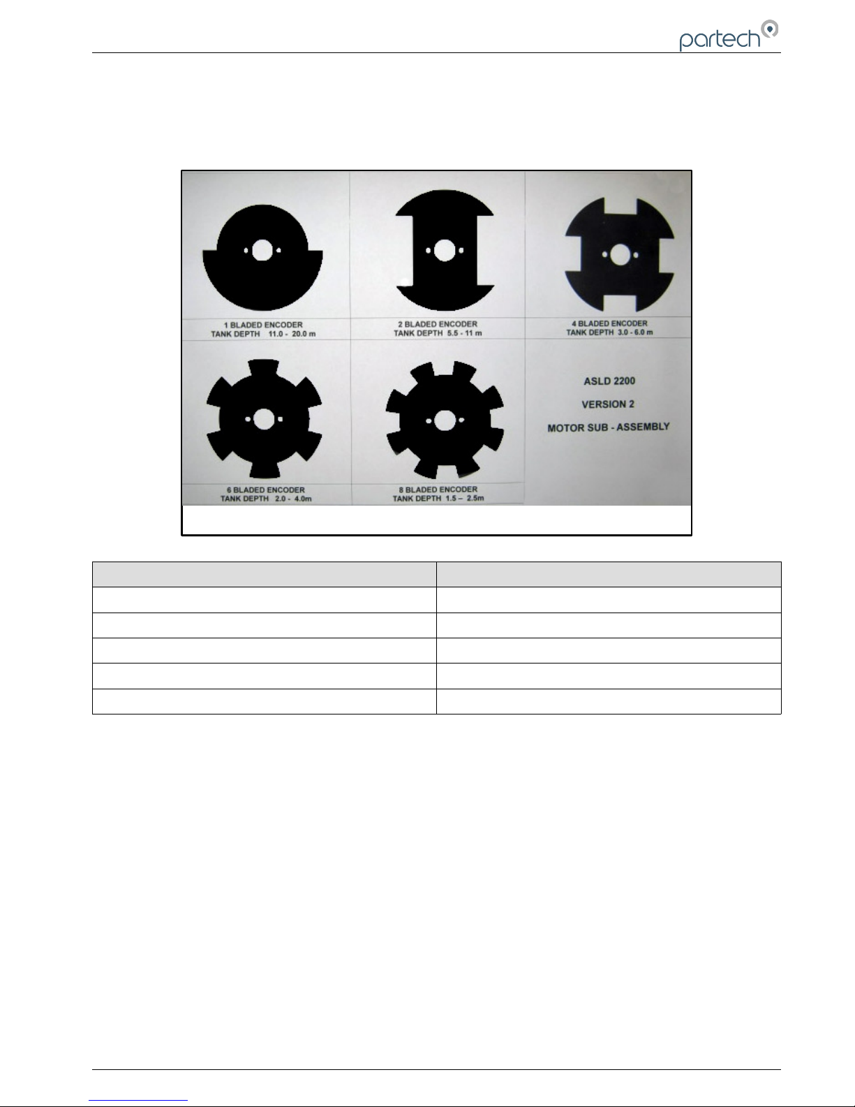
3.2 Encoder Di c Selection..................................................................................................................................... 9
3.2.1 Encoder Di c Range ................................................................................................................................. 9
4 Control Setting ......................................................................................................................................................... 10
4.1 Up and Down Button ..................................................................................................................................... 11
5 In tallation.................................................................................................................................................................. 12
5.1 Location.......................................................................................................................................................... 12
5.2 Electrical Connection .................................................................................................................................... 13
6 Configuration.............................................................................................................................................................. 14
6.1 Sen or Selection............................................................................................................................................. 14
6.2 Depth Range Selection................................................................................................................................... 14
6.3 Link ............................................................................................................................................................... 15
7 Calibration.................................................................................................................................................................. 16
7.1 Set Zero.......................................................................................................................................................... 16
7.2 Set Span......................................................................................................................................................... 16
8 Scraper Clearance..................................................................................................................................................... 17
8.1 Bridge Clearance Control................................................................................................................................ 17
9 Output ...................................................................................................................................................................... 18
9.1 Analogue Output............................................................................................................................................. 18
9.2 Limit Relay...................................................................................................................................................... 18
10 Maintenance............................................................................................................................................................ 19
10.1 General Precaution ..................................................................................................................................... 19
10.2 Routine Maintenance.................................................................................................................................... 19
10.3 Removal of the Printed Circuit Board A embly............................................................................................19
10.4 Sen or replacement...................................................................................................................................... 21
11 Fault Finding............................................................................................................................................................. 22
11.1 Symptom: Digital di play change but doe not relate correctly to the en or po ition.................................22
11.2 Symptom: The en or drive to the top limit................................................................................................. 23
11.2.1 Fault: Sen or i fouled............................................................................................................................. 23
11.2.2 Fault: Faulty External UP Switch............................................................................................................. 23
103370IM I ue 10 Date 19/03/2018 Page 3 of 30

ASLD2200 - In truction Manual
11.3 Symptom: Motor doe not re pond to change in the ludge blanket level; en or working correctly...........24
11.4 Symptom: Exce ive play on cable drum......................................................................................................24
11.5 Sen or operation check................................................................................................................................. 24
12 Spare Part .............................................................................................................................................................. 25
12.1 Sen or.......................................................................................................................................................... 25
12.2 General......................................................................................................................................................... 25
12.3 Repair........................................................................................................................................................... 25
13 Technical Specification ........................................................................................................................................... 26
13.1 General......................................................................................................................................................... 26
13.2 Alarm Output................................................................................................................................................. 26
13.3 Analogue Output........................................................................................................................................... 26
13.4 EMC.............................................................................................................................................................. 26
13.5 Phy ical Feature ......................................................................................................................................... 26
14 Technical Support..................................................................................................................................................... 27
14.1 Returning Equipment for Repair.................................................................................................................... 27
15 Declaration of Conformity......................................................................................................................................... 28
Page 4 of 30 103370IM I ue 10 Date 19/03/2018

ASLD2200 - In truction Manual
1 Introduction
1.1 General
The ASLD2200 i de igned to monitor the po ition of a ludge blanket in a ettlement tank. The y tem u e an
infrared gap type en or to earch for and then track, the interface between the ludge and the water.
Thi information i then provided via both an LED di play and a 4-20 mA output ignal.
1.2 Output Signal
The ASLD2200 provide a 4-20 mA output ignal that i proportional to the location of the top of the ludge blanket.
With a normal etup the 4mA value relate to the bottom of the tank and 20 mA to the water urface.
1.3 Limit Relay
The ASLD2200 provide a relay contact clo ure when the di play read 100% or 0% or both.
1. Manual Conventions
The manual ha been written on the ba i that the u er ha a ba ic knowledge of in trumentation and an
under tanding of the type of mea urement being made.
Training in the u e of the ASLD2200 Monitor can be provided by Partech, plea e contact ale for further information.
103370IM I ue 10 Date 19/03/2018 Page 5 of 30

ASLD2200 - In truction Manual
1.5 Mechanical Overview
The ASLD2200 i compo ed of three component a emblie : The external cable drum and en or, the motor drive
and encoder a embly, and the control electronic enclo ure.
Page 6 of 30 103370IM I ue 10 Date 19/03/2018
DISPLAY
LED
INDICATORS
MOTOR SUB
ASSEMBLY
CABLE
DRUM
DRIVE
BELT
BELT
TENSIONER
SENSOR
ENCODER
BRACKET
ENCODER
ENCODER
DISC
AC MAINS
MOTOR ENCODER
& SENSOR
CONNECTIONS
EXTERNAL SWITCHES,
4-20mA O/P & RELAY
CONNECTIONS
SERIAL
NUMBER
FUSE

ASLD2200 - In truction Manual
2 Principle of Operation
The ASLD2200 u e a Su pended Solid en or to detect the den ity of the ludge & hence the po ition at which the
den ity make a tep change (the interface): The in trument move the en or to a point that i ju t above the
interface, (low SS), then lower the en or below the interface, (high SS), to confirm the po ition of aid interface. The
control regime operating the motor i then ta ked with con tantly o cillating the en or between low & high SS
reading , keeping the en or at the point of interface. Hence detecting whether there i movement. The numeric
di play will how the current value of the interface po ition in term of percentage of liquid level in the tank. 0%
repre ent the bottom, and 100% i the urface the liquid.
The u er i provided with information about the en or reading by the panel of LED’ on the printed circuit board
a embly (PCBA).
The output of the en or i divided a hown in the graph below:
The ‘motor’ LED’ will come on once the related en or LED ha been on for 5 econd and the motor will activate.
The ‘limit ’ LED’ will be u ed when the y tem reache either 0 or 100%
The 3 digit LED di play will indicate the po ition of the ludge blanket a a percentage of the depth of the tank. For
example if the tank i 4 metre deep and the di play i howing 25%, the ludge blanket i 1 metre from the bottom of
the tank
103370IM I ue 10 Date 19/03/2018 Page 7 of 30
PCBA OF DISPLAY PANEL SHOWING LEGENDS
DISPLAY PANEL SHOWING LEGENDS
INTERFACE
SUPERNATENT
CLEAN
WATER
SUSPENDED SOLIDS
SENSOR
OUTPUT
SENSOR ‘LO’
LED ON
BOTH LEDS
OFF
SENSOR ‘HI’
LED ON

ASLD2200 - In truction Manual
3 ASLD2200 Selection
3.1 Sensor Selection
The ASLD2200 i upplied with a IR en or; the correct en or hould have been elected before purcha e. If you are
in any doubt about the en or that ha been upplied plea e contact Partech.
Sen or replacement in the field i ea y to carry out; the table below indicate the normal application of the each of the
four en or range .
IR100 range 0 to 200mg/l
Thi en or i normally u ed for Su pended Solid
mea urement and i not normally applied to Sludge
Blanket mea urement. The en or hould only be u ed if
the ludge i very ‘light’ with very clear upernatant.
IR 0 range 0 to 1,500mg/l
Thi i the mo t commonly u ed en or and i uitable for
u e on final ettlement tank in ewage treatment
application and clarifier in water treatment work .
IR15 range 0 to10,000mg/l
Thi en or i al o regularly u ed for ludge blanket
detection and i normally u ed for primary ettlement in
ewage treatment and ludge thickener in water treatme
IR8 range 0 to 30,000mg/l
Thi en or hould only be applied on ludge thickener in
ewage treatment plant .
Page 8 of 30 103370IM I ue 10 Date 19/03/2018

ASLD2200 - In truction Manual
3.2 Encoder Disc Selection
The ASLD2200 i upplied with a election of encoder di c . The di k choice i dependant on the depth of the
mea urement tank.
3.2.1 Encoder Disc Ranges
Number of Blade Tank Depth (m)
1 11-20
2 5.5-11
4 3-6
6 2-4
8 1.5-2.5
103370IM I ue 10 Date 19/03/2018 Page 9 of 30
ENCODER DISC SELECTION

ASLD2200 - In truction Manual
Control Settings
The principle control during operation i the rotary witch; thi allow the u er to elect the following operation
In ‘AUTOMATIC’ mode the in trument will continually monitor the u pended olid den ity and will move the en or
up and down to track the ludge blanket interface. The MOTOR UP/DOWN and STOP po ition are elf-explanatory
and are only u ed during the etup of the in trument.
On the circuit board there are a number of other control , the function of the e control i explained in later ection :
Circuit Board Identity Type of Control Use
Zero Pu h Button Calibration
Top Limit Potentiometer Calibration
Bridge Clearance Potentiometer Scraper Clearance
VR1 - Motor Speed Control Potentiometer Factory etup
VR5 - 20mA Adju tment Potentiometer Factory etup
VR6 - 4mA Adju tment Potentiometer Factory etup
VR8 - 100% Potentiometer Factory etup
VR9 - 0% Potentiometer Factory etup
SW2 - Up Pu h Button Calibration and
maintenance
SW1 - Down Pu h Button Calibration and
maintenance
J1 - Link A Jumper Setup
J2 - Link B Jumper Setup
Re et Mode Switch Setup
Page 10 of 30 103370IM I ue 10 Date 19/03/2018
PANEL – WITH DISPLAY & CONTROL

ASLD2200 - In truction Manual
.1 Up and Down Buttons
The ASLD 2200 ha 2 et of Up and Down button ; one et i on the out ide of the enclo ure the other et i on the
main printed circuit board (protruding above the front panel). Both et have the ame function. The e button are
normally u ed to aid cleaning of the en or by bringing the en or to the urface.
Up and Stop
Thi button will cau e the en or to ri e to the 100% point at the higher peed.
Down and Reset
Thi button will cau e the en or to return to automatic mea urement
103370IM I ue 10 Date 19/03/2018 Page 11 of 30
EXTERNAL & INTERNAL MOTOR CONTROL BUTTONS

ASLD2200 - In truction Manual
5 Installation
5.1 Location
The ASLD2200 i hou ed in an IP55 GRP outer enclo ure and i uitable for mounting on the bridge of ettlement
tank . The electronic for the monitor are hou ed within an inner IP65 enclo ure.
It i recommended that the monitor be mounted approximately half way between the centre and the out ide wall of the
tank, on the leading edge. Thi offer allow the y tem to monitor the true ettled interface whil t minimi ing the
effect of di turbance cau ed by incoming ludge and by the tank craper.
It i normal for the 4-20 mA output ignal to be tran mitted via lip ring to the ite control y tem, where thi i not
po ible Partech are happy to offer a radio telemetry y tem for tran mi ion directly to the de ired point.
Partech offer a mounting bracket hown below that allow ea y attachment to tank handrail .
The ASLD2200 weigh 15 kg and can be difficult to handle, it i advi able to have a i tance when
in talling thi in trument.
Do not lift the ASLD2200 by its cable drum.
Page 12 of 30 103370IM I ue 10 Date 19/03/2018
TYPICAL MOUNTING ARRANGEMENT & BRACKET DETAIL

ASLD2200 - In truction Manual
5.2 Electrical Connections
Number Function Colour of
Internal Wiring
1
Remote Up Switch
White/Black
2
Remote Down Switch
Orange/Black
3
Remote Switch Common
Yellow/Black
4
4-20 mA Hi (+)
5
4-20 mA Lo (-)
6
Regulated 12v DC Output
7
0v DC
8
Limit Relay, 0% and/or 100%
9
Limit Relay, 0% and/or 100%
10
0v DC
11
Sen or Lo
Blue
12
Sen or 12v
Brown
13
5v DC to Encoder
Red
14
Input 1 from Encoder
Blue
15
Input 2 from Encoder
Yellow
16
0v DC to Encoder
Black
17
Nominal 18v DC to Motor (+ve)
Green
18
Nominal 18v DC to Motor (-ve)
Red/Brown
19
Not U ed
20
Not U ed
21
To main i olator
Red/Brown
22
To main i olator
Red/Brown
23
Earth
24
No connection
25
Neutral
26
Live
The ASLD2200 require a main power upply to operate thi can be either 115 or 230v AC.
Unle pecifically advi ed to do o, do not make change to the internal wiring.
103370IM I ue 10 Date 19/03/2018 Page 13 of 30
PCBA SHOWING TERMINATION DETAILS

ASLD2200 - In truction Manual
6 Configuration
The ASLD2200 require very little configuration, the u er mu t check the following detail before u e. If you find that
the incorrect en or or encoder di c ha been purcha ed contact Partech to arrange a replacement.
6.1 Sensor Selection
The IR en or are available in four range ; which are hown below along with typical application .
Part
Number
Description Typical Application
102201 IR100, Range 0-200 mg/l Water Treatment Clarifier
101901 IR40, Range 0-1,500 mg/l Sewage Treatment Final Settlement Water Treatment Primary
101601 IR15, Range 0-10,000 mg/l Sewage Treatment Primary Water Treatment Thickener
148121 IR8, Range 0-30,000 mg/l Sewage Treatment Thickener
6.2 Depth Range Selection
The depth range depend on the encoder di c that ha been fitted to the in trument, thi can be found near the motor
a embly.
Motor Assembly Version 2
CURRENT VERSION
(Thick aluminium side plates)
Motor Assembly Version 1
OLD VERSION
(Thin stainless steel side plates)
No of Blades Minimum Range
(metres)
Maximum Range
(metres)
Minimum Range
(metres)
Maximum Range
(metres)
1 11.0 20.0 5.6 13.8
2 5.5 11.0 2.8 6.9
4 3.0 6.0 1.4 3.4
6 2.0 4.0 1.0 2.2
8 1.5 2.5 0.8 1.6
The in trument will have been fitted with one of the e encoder di c , and will have been elected prior to order
placement. The encoder di c can be changed in the field if required, ee the rear of the manual for part number .
Page 14 of 30 103370IM I ue 10 Date 19/03/2018

ASLD2200 - In truction Manual
6.3 Links
The circuit board ha two et of link (LINK_A & LINK_B), and a ‘Re et Mode’ witch that need to be et in the
correct po ition for the application.
Link A
When a jumper i placed the ‘ON’ po ition the limit relay will activate when the top limit LED i on – di play i reading
100%. The factory default i for thi jumper to be in the ‘ON’ po ition.
Link B
When a jumper i placed the ‘ON’ po ition the limit relay will activate when the bottom limit LED i on – di play i
reading 0%. The factory default i for thi jumper to be in the ‘ON’ po ition.
RESET MODE SWITCH
Switch to ‘RIGHT’ with white ident towards ‘BLANKET’ label
On power up, either during commi ioning or after a power failure the en or will immediately tart to earch for the
ludge blanket.
Switch to ‘LEFT’ with white ident towards ‘TOP’ Label
On power up, either during commi ioning or after a power failure the en or will lift to the top limit. It will then wait for
the down button to be pre ed.
Thi witch etting will only effect operation with the rotary witch on ‘automatic’. Other etting of the rotary witch will
override thi feature.
The factory etting for thi switch i to the right (with white ident
howing toward ‘BLANKET’)
Switche SW7 & SW9 (a illu trated in the diagram on the right) are
et in the po ition hown. Do not move these switches. They are
intended for future enhancement of ASLD operation.
103370IM I ue 10 Date 19/03/2018 Page 15 of 30
POSITION OF PCBA MOUNTED LINKS & RESET SWITCH
RESET
MODE
SWITCH
LINK A
LINK B
SWITCH in 'UP' POSITION
SWITCH TO THE RIGHT

ASLD2200 - In truction Manual
7 Calibration
Calibration i carried out in 2 tage ; fir tly et the zero point, then the 100% value. A the en or i going to be
lowered to the bottom of the tank it i important that attention i paid to any hazard uch a moving craper below
the urface of the tank.
NOTE: The Zero & 100% potentiometer mounted on the PCBA play no part in the calibration routine.
7.1 Set Zero
Set the rotary witch to ‘motor top’ and
take the en or down to the bottom of the
tank by taking loop of cable off the drum.
Once the cable i clo e to the bottom of
the tank gently rai e and lower the en or
and it will be po ible to ‘feel’ the bottom
of the tank. U e the ‘motor up’ po ition of
the rotary witch to move the en or uch
that it i approximately 25 mm from the
bottom of the tank. Pre the Red Zero
pu h button to et the zero point, it i
ometime nece ary to pre thi button
a few time to en ure a correct zero
etting.
It i important that the zero point i et
above the bottom of the tank, if the
en or i allowed to drag on the floor of
the tank damage can occur and there i a
danger that the en or can become
entangled in the craper mechani m.
7.2 Set Span
Now u e the ‘motor up’ po ition to bring
the en or to the water urface. It i
normally advi able to leave the bottom
part of the en or (approximately 50 mm)
under the urface.
Set the rotary witch to ‘motor top’ and
adju t the Top Limit potentiometer until
the TOP LIMIT LED come on (3 digit
LED di play hould approx be 100)
It i advi able to run the in trument back
down to 0 to confirm that the calibration
ha been performed ati factorily.
Page 16 of 30 103370IM I ue 10 Date 19/03/2018
ROTARY
SWITCH
STEP 1 – ZERO CALIBRATION
STEP 2 – SPAN CALIBRATION
DO NOT USE
THESE POTS
FOR SETTING
UP
CALIBRATION

ASLD2200 - In truction Manual
8 Scraper Clearance
In certain application uch a tho e where the ASLD2200 i in talled on a fixed bridge above a moving craper it i
nece ary to bring the en or above the water urface to prevent damage to the en or.
The ASLD2200 allow the u er to in truct the en or to ri e to 100% to allow the craper to pa and then return to
the tank to continue mea urement.
It i recommended that the in taller con ult Partech before tarting in tallation to en ure that the correct mea ure are
taken to prevent damage to either in trument or to the craper mechani m.
Under normal circum tance it i po ible to place a detector ahead of the bridge that will provide the ‘up’ command
and another en or after the bridge that will provide the ‘down’ command.
The e external en or can be wired in parallel to the up and down button on the out ide of the enclo ure u ing
terminal 1 to 3.
8.1 Bridge Clearance Control
A ociated with the craper clearance function i the Bridge Clearance adju tment, thi allow the en or to come
clear of the water to allow the craper to pa . To adju t u e the following tep :
Rai e the en or to the urface u ing the rotary witch.
Select ‘motor off’
Turn off power
Set RESET MODE SWITCH to the LEFT (White Ident to the right)
Turn on power
Select ‘motor up’ and turn the bridge clearance control clockwi e until the en or i rai ed far enough to allow the
craper to pa . Thi can be et to a maximum of 110%.
Return the unit to ‘automatic’ and pre down to return to mea urement.
If power i temporarily lo t the en or will ri e to the urface on power up and remain there until the craper pa e
after which it will return to automatic mea urement.
103370IM I ue 10 Date 19/03/2018 Page 17 of 30

ASLD2200 - In truction Manual
9 Outputs
9.1 Analogue Output
The ASLD2200 ha one analogue output that i directly proportional to the 0 to 100% digital di play. Under normal
circum tance thi relate to 4 mA with the en or at the bottom of the tank and 20 mA with the en or at the water
urface.
There i no need to make any field adju tment during commi ioning. If during maintenance it i felt that the 4-20 mA
ignal need calibration thi can be carried out u ing the 4 mA and 20 mA potentiometer adju tment .
To calibrate the analogue output connect a multimeter on the mA etting. Remove J13 and connect multimeter acro
Pin 4 & 5. The ‘motor up’ and ‘motor down’ control can then be u ed to force the output to 4 mA and 20 mA a
nece ary.
If the ‘Up’ button i pre ed at any time the 4-20 mA loop will go to 12 mA until the ‘Down’ button i pre ed and the
ludge blanket i detected.
9.2 Limit Relay
The ASLD2200 i equipped with a relay that i normally open; when either the top or bottom limit i reached thi
contact will clo e. Either or both top and bottom limit can cau e thi relay to activate, link A and B are u ed to
configure thi feature.
It hould be noted that the trip point i not adju table.
Page 18 of 30 103370IM I ue 10 Date 19/03/2018

ASLD2200 - In truction Manual
10 Maintenance
10.1 General Precautions
Do not lift the unit by the drum
Check that the unit i bolted firmly to the upport bracket
Warning: I olate the main upply before commencing any maintenance to the electronic enclo ure; the external
witch doe not i olate the electronic
10.2 Routine Maintenance
The en or will require routine cleaning; the frequency of cleaning i ite dependent and hould be determined by
ob ervation of the en or during the fir t few week of operation.
Typically the en or hould be cleaned once per fortnight, although on many ite once per month i ufficient.
The en or can be cleaned u ing a oft cloth; no pecial cleaning material are required.
Care mu t be taken to en ure that no loop of cable are di placed during cleaning and the en or hould be lowered
carefully into the tank after cleaning.
10.3 Removal of the Printed Circuit Board Assembly
1. Un crew thumb crew and remove Front panel
2. Un crew 3 pozi crew and remove terminal cover.
103370IM I ue 10 Date 19/03/2018 Page 19 of 30
FRONT PANEL SCREWS
1
2

ASLD2200 - In truction Manual
3. Remove 3x Orange connector
4. Remove 2X Nylon pillar
5. Un crew earth nut and remove earth wire
6. Remove 2x Po i head crew and remove printed circuit board a embly
Page 20 of 30 103370IM I ue 10 Date 19/03/2018
6
4
5
3
PCBA SCREWS
Table of contents
Other ParTech Accessories manuals
Popular Accessories manuals by other brands

Jung
Jung DS 4092 TS Product documentation

Lanaform
Lanaform Heating Overblanket Instructions for use

iTrainer
iTrainer iTrainer Mini quick start guide

Bennett Marine
Bennett Marine AutoTrimPro installation instructions

Propel Trampolines
Propel Trampolines PowerBank+ Bluetooth instruction manual

Sonoff
Sonoff SNZB-04 user manual