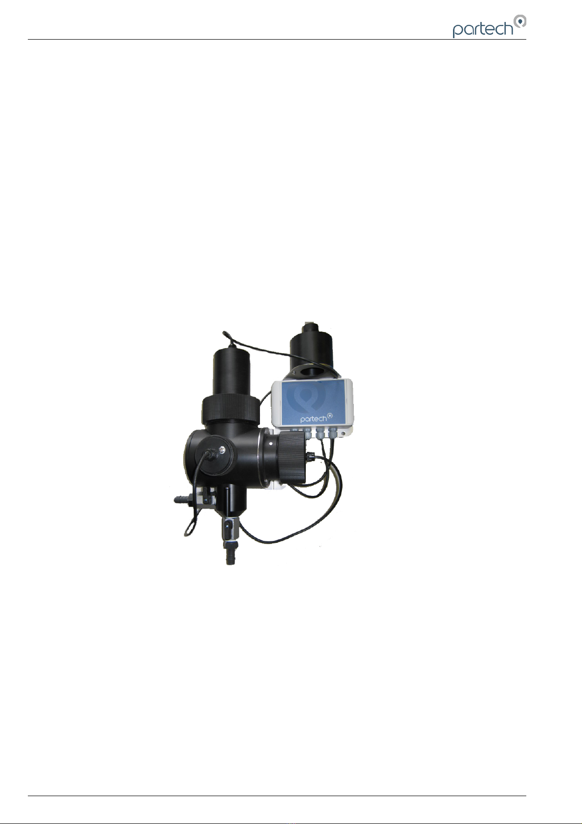
TurbiTechw² LR Instruction Manual
7.4.3 S:0x Remove............................................................................................................................... 17
7.4.4 S:0x Modbus Address.................................................................................................................. 17
7.4.5 S:0x Clean Con ig........................................................................................................................ 17
8 Measurement Con iguration......................................................................................................................... 19
8.1 Measurement Con ig............................................................................................................................ 19
8.1.1 Measurement Status.................................................................................................................... 19
8.1.2 Add Measurement.......................................................................................................................19
8.2 M:0x – Measurement Channel............................................................................................................. 20
8.2.1 M:0x In o...................................................................................................................................... 20
8.2.2 M:0x Title..................................................................................................................................... 20
8.2.3 M:0x Units................................................................................................................................... 20
8.2.4 M:0x Set Zero.............................................................................................................................. 20
8.2.5 M:0x Set Cal................................................................................................................................ 20
8.2.6 M:0x Averaging............................................................................................................................ 20
8.2.7 M:0x Remove............................................................................................................................... 20
8.2.8 M:0x Display Position..................................................................................................................20
9 Calibration.................................................................................................................................................... 21
9.1 Calibration Frequency..........................................................................................................................21
9.2 Equipment required or Formazine Calibrations...................................................................................21
9.3 Calibration Zero................................................................................................................................... 22
9.4 Calibration Span.................................................................................................................................. 23
9.5 Span Calibration using the Take Sample Routine...............................................................................23
9.5.1 Take Sample................................................................................................................................ 24
9.5.2 Sample Result.............................................................................................................................25
10 Maintenance............................................................................................................................................. 26
10.1 General cleaning................................................................................................................................ 26
10.2 Inspection.......................................................................................................................................... 26
10.3 Dismantling the Sensor......................................................................................................................26
10.3.1 Removing the Modules..............................................................................................................26
11 Spares....................................................................................................................................................... 27
11.1.1 Service Parts.............................................................................................................................27
12 Sensor Faults............................................................................................................................................. 28
12.1 Unstable reading on controller........................................................................................................... 28
12.2 Error Codes rom 7300w² Monitor...................................................................................................... 28
12.2.1 Input High Limit/Low Limit..........................................................................................................28
12.2.2 Over range/Under range............................................................................................................28
13 General Application Notes.........................................................................................................................29
13.1 Preparation o Formazin Turbidity Standard......................................................................................29
13.1.1 Health & Sa ety Precautions......................................................................................................29
13.1.2 Method o Preparation............................................................................................................... 29
13.1.3 Preparation o Dilution’s............................................................................................................. 29
13.1.4 Calibration.................................................................................................................................. 29
13.1.5 Storage Li e............................................................................................................................... 29
14 Technical Support...................................................................................................................................... 31
14.1 Returning Equipment or Repair........................................................................................................31
Page of 3 225769IM - Issue - 05 Issue Date 30/0 /2019