ParTech SoliTechw2 IR Series User manual

INSTRUCTION MANUAL
SoliTechw² IR Sensor
Suspended Solids Sensor
For use with 7300w² Monitor

This page is intentionally left blank

SoliTechw² IR Sensor
Table of Contents
1 Introduction.................................................................................................................................................................. 5
1.1 SoliTechw² IR Sensors..................................................................................................................................... 5
1.1.1 Light Absorption........................................................................................................................................... 5
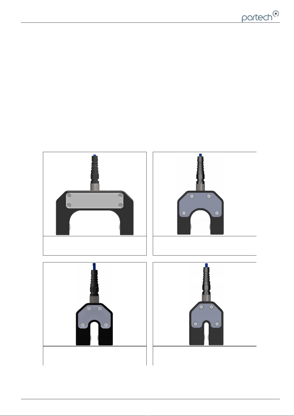
1.1.2 Mounting Options......................................................................................................................................... 6
2 Mechanical Installation................................................................................................................................................. 7
2.1 Location............................................................................................................................................................ 7
2.2 Partech Brackets............................................................................................................................................... 7
2.3 Customer Supplied Brackets............................................................................................................................. 7
3 Electrical Installation.................................................................................................................................................... 8
3.1 Cable Routing................................................................................................................................................... 8
3.2 Connection Details............................................................................................................................................ 8
1 SoliTechw² IR Sensor Configuration............................................................................................................................ 9
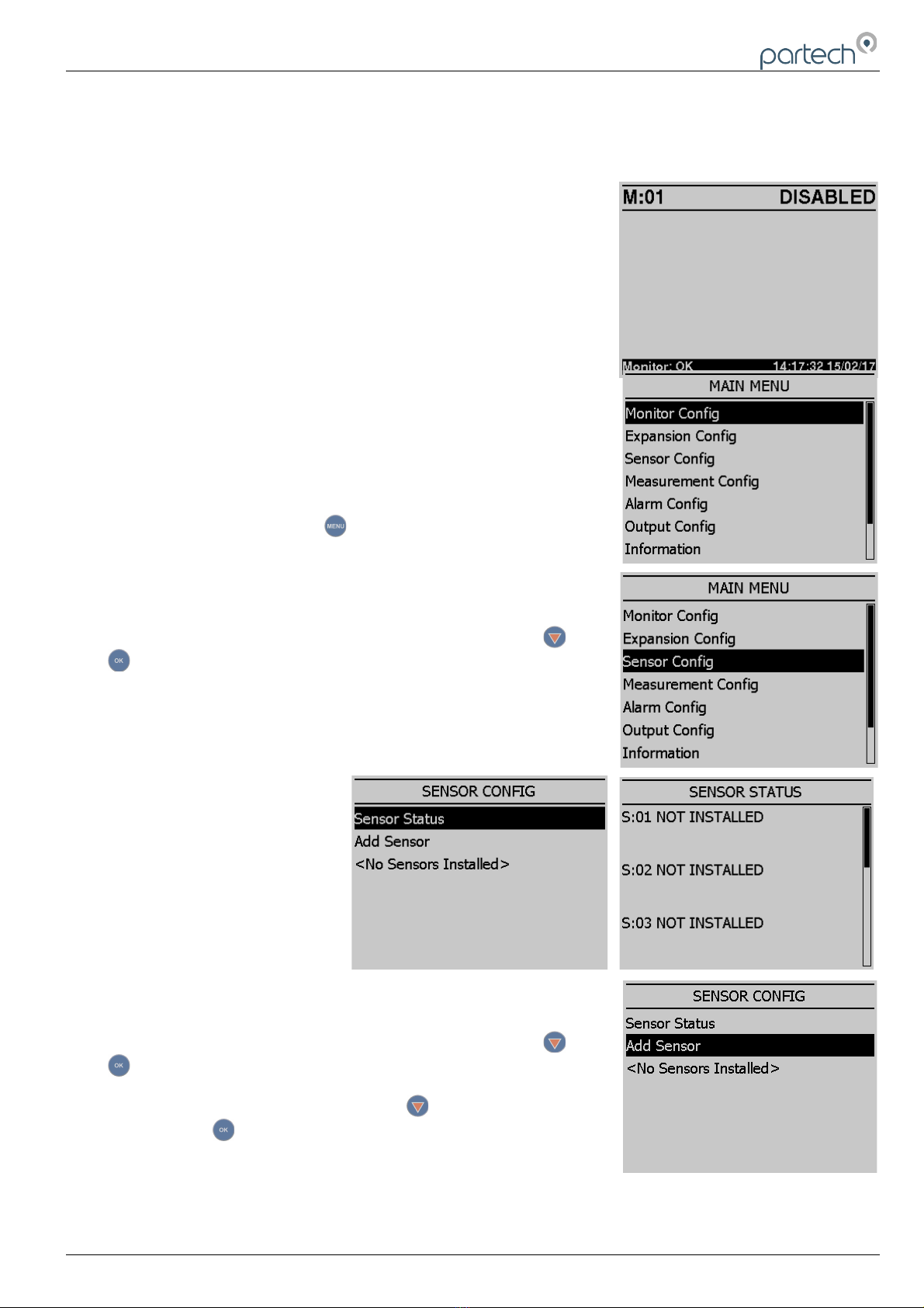
1.1 Sensor Config................................................................................................................................................... 9
1.2 Sensor Status................................................................................................................................................... 9
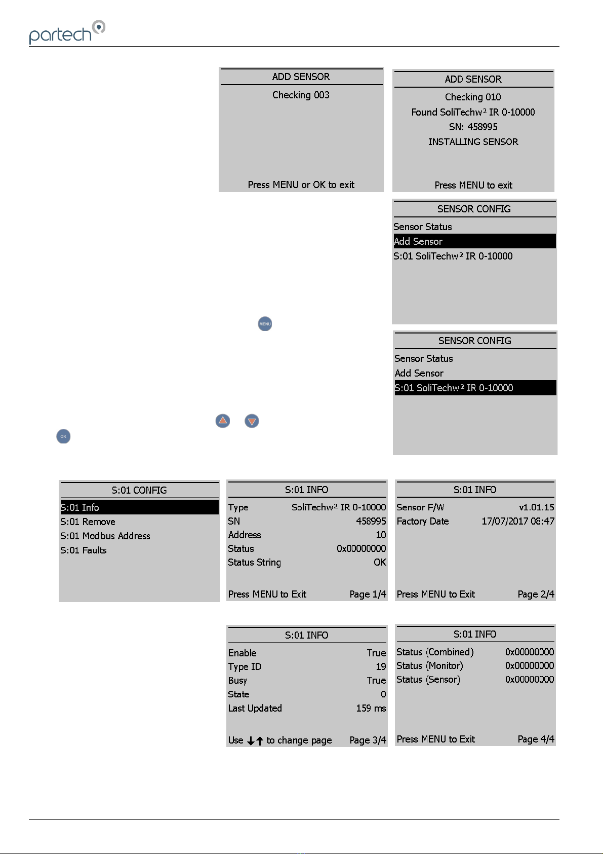
1.3 Add Sensor....................................................................................................................................................... 9
1.1 S:0x SoliTechw² IR 0-xxxxx............................................................................................................................ 10
1.1.1 S:0x Info...................................................................................................................................................... 10
1.1.2 S:0x Remove.............................................................................................................................................. 11
1.1.3 S:0x Modbus Address................................................................................................................................. 11
2 Measurement Configuration....................................................................................................................................... 12
2.1 Measurement Config....................................................................................................................................... 12
2.1.1 Measurement Status................................................................................................................................... 12
2.1.2 Add Measurement....................................................................................................................................... 12
2.2 M:0x – Measurement Channel........................................................................................................................ 13
2.2.1 M:0x Info..................................................................................................................................................... 13
2.2.2 M:0x Title.................................................................................................................................................... 14
2.2.3 M:0x Set Zero............................................................................................................................................. 14
2.2.4 M:0x Set Cal............................................................................................................................................... 14
2.2.5 M:0x Take Sample...................................................................................................................................... 14
2.2.6 M:0x Sample Result.................................................................................................................................... 14
2.2.7 M:0x Averaging........................................................................................................................................... 14
2.2.8 M:0x Remove.............................................................................................................................................. 15
2.2.9 M:0x Display Position.................................................................................................................................. 15
2.2.10 Restore Defaults....................................................................................................................................... 15
3 Calibration.................................................................................................................................................................. 16
3.1 Preparation for Calibration.............................................................................................................................. 16
3.2 Calibration Frequency..................................................................................................................................... 16
3.3 Calibration Solutions....................................................................................................................................... 16
3.4 Zero Calibration.............................................................................................................................................. 16
3.5 Span Calibration............................................................................................................................................. 17
3.6 Take Sample................................................................................................................................................... 18
3.7 Sample Result................................................................................................................................................. 18
228655IM-Iss05 Issue Date 25/08/2020 Page 3 of 26

SoliTechw² IR Sensor
4 Spare Parts List......................................................................................................................................................... 20
4.1 Sensors........................................................................................................................................................... 20
4.2 Monitor............................................................................................................................................................ 20
4.3 Mounting Accessories..................................................................................................................................... 20
4.4 Miscellaneous................................................................................................................................................. 20
5 Technical Support...................................................................................................................................................... 21
5.1 Returning Equipment for Repair...................................................................................................................... 21
6 Technical Specification.............................................................................................................................................. 22
6.1 General........................................................................................................................................................... 22
6.2 Environmental Data........................................................................................................................................ 22
6.3 Measurements................................................................................................................................................ 22
7 Appendix 1: Fuller's Earth.......................................................................................................................................... 23
Page 4 of 26 228655IM-Iss05 Issue Date 25/08/2020

SoliTechw² IR Sensor
1 Introduction
This manual covers the SoliTechw² IR range of sensors as used on the 7300w² monitor. For more extensive
explanation regarding menus etc. the manual covering the 7300w² monitor should be referred to. For IR sensors used
with 750w² hand-held monitor or either the ASLD2200, 7100, 7200, 8100 or 8200 monitors, please see appropriate
instruction manual. The SoliTechw² IR sensors (as listed within the illustrations below) are not compatible with any
platform other than the 7300w² monitor. Whilst every attempt has been made to ensure that the instructions are
correct, common sense and good engineering practice should always be used to adapt to specific site details. If you
are in any doubt, please contact Partech or your local distributor for further information.
1.1 SoliTechw² IR Sensors
All SoliTechw² IR sensors use an infrared light source, which offers long-term stability, low maintenance and high
reliability. The principle of operation is described below.
1.1.1 Light Absorption
The SoliTechw² IR sensor family is intended to monitor suspended solids in four predetermined nominal ranges. Each
sensor is available as a 10metre or 20metre option.
No internal adjustment is possible, but measurement outside these ranges is sometimes possible and maybe
determined by experimentation. All range statements are based on solids present on a typical sewage treatment
works, and although they are useful as guidance, the ranges will be affected by the nature of the solids being
monitored.
228655IM-Iss05 Issue Date 25/08/2020 Page 5 of 26
SoliTechw² IR Sensor (Range: 0-200 mg/l)
PN223893 10 metre cable
PN223894 20 metre cable
SoliTechw² IR Sensor (Range: 0-1,500 mg/l)
PN223895 10 metre cable
PN223896 20 metre cable
SoliTechw² IR Sensor (Range: 0-10,000 mg/l)
PN223897 10 metre cable
PN223898 20 metre cable
SoliTechw² IR Sensor (Range: 0-30,000 mg/l)
PN223899 10 metre cable
PN223900 20 metre cable
100mm Gap 40mm Gap
15mm Gap 8mm Gap

SoliTechw² IR Sensor
The sensor uses the light absorption principle, with the light source an infrared LED operating at 950nm. In simple
terms, the sensor detects solids by comparing the amount of light emitted by the LED with the amount received by the
photo-diode. The amount of solids present is inferred from the reduction in received light.
The sensor has been designed to monitor Suspended Solids throughout the treatment process.
1.1.2 Mounting ptions
A range of mounting options are available for the SoliTechw² IR sensors, which will allow the user to apply the sensor
in a wide variety of locations. This manual addresses Suspended Solids Detection applications. Please contact
Partech for other types of application. When assessing mounting options, attention should be paid to the accessibility
of the sensor for calibration and maintenance, stability of the sensor in the flow conditions present on site and to
ensuring the sensor is fully submerged at all times. It is recommended that the sensor is located in an area where
there is sufficient movement to keep the solids in suspension and where any turbulence provides minimum impact on
the sensors.
Page 6 of 26 228655IM-Iss05 Issue Date 25/08/2020

SoliTechw² IR Sensor
2 Mechanical Installation
2.1 Location
Reliable accurate measurement from any instrument can only be achieved by correct installation of the measuring
device; in the case of suspended solids, this is particularly important. If you are in any doubt, contact Partech or your
local distributor for advice.
Below are some points that should be considered before installing the SoliTechw² IR sensor, and if the sensor is failing
to obtain the results expected.
Avoid areas of extreme flow or turbulence; air bubbles will disturb the reading.
The sensor should be mounted in such a way as to allow easy access for calibration and maintenance. It
should be possible to remove the sensor from the process without the need to shut the process down.
To allow a single technician to calibrate and maintain the system the sensor should be placed within sight of
the monitor. Although cable runs of up to 100 metres are possible, operational problems can be caused.
2.2 Partech Brackets
Partech offer a mounting bracket, PN171290 for the installation of the SoliTechw² IR sensors which suits most
applications.
Fig 2 Handrail Bracket
2.3 Customer Supplied Brackets
When creating brackets to mount the SoliTechw² IR sensor, care should be taken to ensure that the following
guidelines are observed:
The bracket must be strong enough to support the sensor with minimum movement when installed into the
sample.
When attachments to the sensor are made, these should be done using the threaded area at the top of
the sensor housing or by clamping around the sensor body.
Consideration should be given to enable simple removal and replacement of the sensor for the inspection,
calibration and servicing to be carried out.
228655IM-Iss05 Issue Date 25/08/2020 Page 7 of 26

SoliTechw² IR Sensor
3 Electrical Installation
The SoliTechw² IR sensor connects to the 7300w² monitor. The information below provides the physical installation
instructions; please refer to the monitor instruction manual for complete setup details.
3.1 Cable Routing
Care should be taken to ensure that the cable routing does not cause problems with the sensor measurement; good
engineering practice should be followed with particular attention being paid to the following points;
The sensor cable should be kept to the minimum length possible.
Sufficient spare cable should be provided to allow complete and easy removal of the sensor from the process.
Any spare cable should be safely stored.
The sensor cable should be kept separate form mains cable.
3.2 Connection Details
All sensors within the w² family of instruments are connected to the 7300w² Monitor using the same 4 wire
configuration.
•RED and BLACK wires provide the 12VDC supply to the sensor and the communication ground.
•WHITE and GREEN provide data communication.
A maximum of two sensors can be directly connected to the standard 7300w² Monitor, however additional sensors can
be added using the optional Expansion Boxes available separately.
Remove the 4-way connector from the 7300w² Monitor by pulling downwards to disconnect for easy access to the
connections. Connect the sensor cores as follows:
(Terminals from left to right on the 4 way connector)
Term 1 (Left) - RED (+12V)
Term 2 - Black (0V) and Drain
Term 3 - White (Data A)
Term 4 (Right) - Green (Data B)
Always connect the screen drain wire with the Black (Term 2). Illustration Left shows drain wire and Black wire
connected together, and covered in Black Heat shrink.
Always use Bootlace ferrules when terminating the sensors to ensure a good connection to the terminals.
Page 8 of 26 228655IM-Iss05 Issue Date 25/08/2020

SoliTechw² IR Sensor
1 SoliTechw² IR Sensor Configuration
Before attempting to configure the SoliTechw² IR sensor, please read the user manual that came with your monitor.
The monitor manual will introduce you to the basic set-up of the monitor, and
will familiarise you with the monitor menu structure and buttons.
The monitor leaves the factory with no sensors pre-installed.
Assuming the monitor has been physically connected to a sensor, the next
step is to register and configure the sensor before any measurements can be
made. A single sensor may provide one or more measurements. We advise
only adding one sensor at a time. Once the first sensor has been registered,
connect the second and register again. Repeat for any additional sensors.
All sensors must be registered to the monitor in this way, even if they are
different types.
Please note that live measurements are not available until the sensor
Configuration stage has been completed.
1.1 Sensor Config
From the Measurement screen press to access the MAIN MENU.
From the MAIN MENU screen, select SENSOR CONFIG by pressing , and
press to accept.
1.2 Sensor Status
This option allows the user to review the
current status of the 8 sensor channels,
these will all be set to disabled until a
sensor is added.
Once a sensor has been installed the
display will be updated to indicate the
sensor type installed and it's status.
1.3 Add Sensor
From the MAIN MENU screen, select SENSOR CONFIG by pressing and
press .
The SENSOR MENU should be displayed. Press to highlight ADD
SENSOR, and press .
228655IM-Iss05 Issue Date 25/08/2020 Page 9 of 26

SoliTechw² IR Sensor
The Monitor will now search all
possible addresses (0 to 240) to find
any attached sensors. During the
search, any sensors found will be
displayed momentary before
continuing with the search.
Once the search is complete, the Monitor will display a list of sensors found.
Each sensor will be automatically allocated a new address from S:01 to S:08.
Repeat the above process to install a second, third or more sensors. A total of
8 sensors are possible (expansion box may be required to add additional
sensors).
Sensor addition is now complete.
If a single or multiple sensors have been found the can be pressed to
escape from continuing the search.
1.1 S:0x SoliTechw² IR 0-xxxxx
Once the sensor has been added and registered, the monitor will provide a list
of functions specific to the sensor. Press or to select the sensor and
press . The CONFIG MENU will display a list of sensor functions.
1.1.1 S:0x Info
This function provides a range of diagnostic information that may be requested by Partech for fault finding
As can be observed from screenshots above, Page 1 displays sensor type and sensor serial number. Page 2 displays
firmware version and date. The other pages display various statuses.
Page 10 of 26 228655IM-Iss05 Issue Date 25/08/2020

SoliTechw² IR Sensor
1.1.2 S:0x Remove
This allows the sensor to be removed for re-configuration of the monitor or if a sensor has been added on error. If a
sensor has been replaced with a new sensors, the old sensor must be removed, and the new sensor installed.
You will be prompted with 'Are you sure?' before the sensor is removed. Press to accept and remove.
1.1.3 S:0x Modbus Address
This option allows manual adjustment of the
ModTechw² address for the sensor, under
normal circumstances this should not be
changed. If there is same sensor type
duplication within one monitor, then the
modbus address will require changing to
avoid conflict.
228655IM-Iss05 Issue Date 25/08/2020 Page 11 of 26

SoliTechw² IR Sensor
2 Measurement Configuration
The monitor leaves the factory without any measurements configured.
Measurements can only be added after installing the relevant sensor(s).
Once the sensor(s) have been registered with the monitor and installed, the
measurements will now be available.
2.1 Measurement Config
From the MAIN MENU screen, select MEASUREMENT CONFIG by pressing
, press .
The screen shot to the left shows the default configuration after the installation
of the SoliTechw² IR sensor on a single sensor configuration:
2.1.1 Measurement Status
This option allows the user to review the current status of the 16 measurement
channels, these will all be set to disabled until a sensor is added. In the
example above the first channel will be
occupied.
From the MAIN MENU screen, select
MEASUREMENT CONFIG by pressing
, press . On MEASUREMENT CONFIG
screen the first option is MEASUREMENT
STATUS: Press to select.
Once a measurement has been configured
the display will be updated to indicate the
measurement and it's status.
2.1.2 Add Measurement
The ADD MEASUREMENT option is
required to include additional measurement
types (usually alternate units) derived from
the same sensor. The screenshots on the
right show with the SoliTechw² IR sensor
measurements removed. There is only one
measurement option included with the SoliTechw² IR range of sensors.
The MEASUREMENT CONFIG menu should be displayed. Press to
highlight ADD MEASUREMENT, and press .
All available measurements will be displayed in a list. Press or to select
the required measurement. If the desired measurement is not listed it may be
possible to add measurement anyway, which will result in a repetition of existing
parameter, which can then be edited regarding title as described later.
Press to select the measurement. Repeat the process if more measurements are required.
Each measurement will be allocated a measurement number from M:01 – M:16. A total of 16 measurements may be
displayed.
Press to return back to the display screen. Your first measurement configured should now be displayed. If two
measurements were configured, press to cycle through the display screens to show 2 measurements, 3
measurements etc.
Page 12 of 26 228655IM-Iss05 Issue Date 25/08/2020

SoliTechw² IR Sensor
The Measurement Menu will list all configured measurements in order M:01 to M:16 the list will also indicate the
sensor number that is delivering the signal for the measurement.
2.2 M:0x – Measurement Channel
Selecting a measurement channel will reveal a new sub-menu associated with
that measurement. In MEASUREMENT C NFIG press to highlight the
required measurement and press .
It is important to recognise that the first and primary measurement M:01 is the
only channel that is used for sensor calibration and displaying of diagnostics data.
The sub-menu is as follows:
2.2.1 M:0x Info
This option provides additional information on the measurement. This
information will usually be required if a problem exists with the sensor
performance. There are eight diagnostic screens under the 'INFO' menu which
display parameters such as faults, timing, statuses etc.
228655IM-Iss05 Issue Date 25/08/2020 Page 13 of 26

SoliTechw² IR Sensor
2.2.2 M:0x Title
This allows the title of the measurement to
be changed from it's default, the
measurement title is used in measurement
mode to identify the measured value. A
selection of standard terms are available
along with a 'User Defined' option that can
be adjusted to suit your requirements. For
example this could be changed to 'Solids
Line 1'. The maximum number of characters
is 20.
In MEASUREMENT C NFIG press to highlight the required title and press to select. A tick will appear along
side the accepted title.
2.2.3 M:0x Set Zero
The term relates to the calibration of the system and is covered in the Calibration section below.
2.2.4 M:0x Set Cal
The term relates to the calibration of the system and is covered in the Calibration section below.
2.2.5 M:0x Take Sample
The term relates to the calibration of the system and is covered in the Calibration section below.
2.2.6 M:0x Sample Result
The term relates to the calibration of the system and is covered in the Calibration section below.
2.2.7 M:0x Averaging
In MEASUREMENT C NFIG press to
highlight the required title and press to
select.
This allows the user to impose averaging on the
measured value, this is used to reduce the
speed of reaction to the process changes.
The following values are available for the user to select:
Damping Rate Response Time (Seconds) Typical Use
Instant 0.2s Instrument demonstration and test
Very Fast 1s Applications with dynamic solids changes
Fast 10s Normal expected operational use
Medium 30s
Slow 1m
Very Slow 2m Reduce spurious alarms from brief solids changes
Page 14 of 26 228655IM-Iss05 Issue Date 25/08/2020

SoliTechw² IR Sensor
2.2.8 M:0x Remove
In MEASUREMENT C NFIG press to
highlight the required title and press to
select.
This option allows the user to remove a
measurement that has been selected in error
or to allow re-configuration of the system.
Please use this option with care, all user
settings for that measurement will be lost if the
measurement is removed in error.
Press again to confirm operation.
2.2.9 M:0x Display Position
In MEASUREMENT C NFIG press to
highlight the required title and press to
select.
This option allows the position of the
measurement to be moved. For example the
suspended solids measurement can be changed from M:01 to M:02 so it will appear second on the list in
MEASUREMENT CONFIG menu. Any associated alarms and outputs will automatically move with the renumbered
measurements.
2.2.10 Restore Defaults
In MEASUREMENT C NFIG press to
highlight the required title and press to
select.
This option will restore the measurement fields
for that particular measurement to the default
values. For example; display position,
averaging value etc.
228655IM-Iss05 Issue Date 25/08/2020 Page 15 of 26

SoliTechw² IR Sensor
3 Calibration
This section covers the operation and calibration of the SoliTechw² IR sensor.
3.1 Preparation for Calibration
When a new system is installed, a period of ½ hour should be allowed for the SoliTechw² IR sensor to stabilise before
calibration commences. This is to enable the system to adjust to the “new” ambient conditions. This should not be
considered as system warm up time from power up, but to acclimatise to the environment if the sensor has come from
a warm store to a cold sample point.
The standard calibration procedure involves a two point calibration – zero and span, the process for calibration is
described below. The sensors have linear responses to most the solids found in most applications, if a particular
application has a non-linear response it is possible to adapt the response of the sensor to improve accuracy, this must
be carried out in consultation with Partech.
Any containers used to store calibration samples should be cleaned prior to use. To ensure accurate calibration the
sensor must be placed into the solution within the container for zero and span calibration.
3.2 Calibration Frequency
There is no absolute guide to the frequency of calibration. The user must make a judgement based on how critical the
measurement is to the process, variability in the sample and standard practice within their organisation.
We recommend that calibration is carried out at commissioning stage and is then repeated within 4 weeks to ensure
the instrument and process conditions are stable. After this a default calibration frequency is every 3 to 6 months.
3.3 Calibration Solutions
There is no absolute material that constitutes the ideal calibration solution. Although the sensor will have been factory
calibrated using clean tap water for the zero, and fullers earth for the span (see section 10). These calibrations will
have been carried out employing the following 'ZERO CALIBRATION' and the 'SPAN CALIBRATION' procedures. The
former 'ZERO CALIBRATION' is the primary (and only) methodology employed to zero the sensor. The primary
methodology for calibration of the measurement is the 'TAKE SAMPLE – SAMPLE RESULT' procedure. The 'SPAN
CALIBRATION' has been included here for completeness.
3.4 Zero Calibration
From the 7300w² Monitor, navigate to the
Calibration menu as follows-
Press to show the “MAIN MENU”.
Select “MEASUREMENT CONFIG” by
pressing and press to accept.
Select “Suspended Solids mg/l” by
pressing and press to accept.
(Ensure the measurement channel you have
chosen has the same engineering units as
the intended calibration solutions)
Select “SET ZERO” by pressing and
press to accept.
The SET ZERO information screen will be
displayed. Press to move on.
The ZERO Calibration screen will be displayed.
Page 16 of 26 228655IM-Iss05 Issue Date 25/08/2020

SoliTechw² IR Sensor
Wait for the value to stabilise, then press
to accept. The calibrating progress bar will be
displayed, followed by the CALIBRATION
SUCCESSFUL screen.
Press to return back to the
MEASUREMENT CONFIG screen.
Zero calibration is now complete.
3.5 Span Calibration
A representative sample from the application with a known value, or Fullers Earth can by used for the span calibration.
From the 7300w² Monitor, navigate to the Calibration menu as follows-
Press to show the “MAIN MENU”.
Select “MEASUREMENT CONFIG” by
pressing and press to accept.
Select “Suspended Solids mg/l” by
pressing and press to accept.
(Ensure the measurement channel you
have chosen has the same engineering
units as the intended calibration solutions)
Select “SET CAL” by pressing and press
to accept.
The SET CAL information screen will be
displayed. Press to move on.
Enter the value for the calibration standard
(Default is 50000mg/l). Press or to
move the cursor below the digit to be
changed. Press or to increase or
decrease the digit, and press the to
accept the value.
The SET CAL calibration screen will now be
displayed.
Wait for the value to stabilise, then press
to accept. Progress bar will be displayed
followed by CALIBRATION SUCCESSFUL
screen.
Press to return back to the
MEASUREMENT CONFIG screen.
228655IM-Iss05 Issue Date 25/08/2020 Page 17 of 26

SoliTechw² IR Sensor
3.6 Take Sample
'Take sample' along with 'Sample Result' work in tandem to calibrate the sensor within the process it is deployed. This
method should be viewed as the primary mode to validate readings from the sensor. The function will compensate for
variances in particle size and density between different processes, materials and even within the same process if
variable at different times of year.
In MEASUREMENT C NFIG press to
highlight 'TAKE SAMPLE' and press to
select.
Press to select the next screen, which
displays general sensor information: Serial
number etc.
Press to progress to screen showing details
of the previous 'TAKE SAMPLE' . If previously
not undertaken, this will display 'None'.
Otherwise the date and user title of that
procedure will be shown.
Press to select the next screen, which is
the reading stabilisation page.
Insert sensor into calibration sample and wait
for the measurement to stabilise.
Press to store sample.
A progress bar will be displayed followed by
the SAMPLE SUCCESSFUL screen.
Press to return back to the MEASUREMENT CONFIG screen.
The Take sample procedure is now complete.
The sample used for this procedure can now be laboratory analysed to
determine the exact weight of solids it contains. This result from analysis will be
carried forward to the SAMPLE RESULT operation.
3.7 Sample Result
In order to utilise this function, a ‘TAKE SAMPLE’ operation must have previously been carried out.
In MEASUREMENT C NFIG press to
highlight 'SAMPLE RESULT' and press to
select.
Press to select the next screen, which
displays general sensor information: Serial
number etc.
Page 18 of 26 228655IM-Iss05 Issue Date 25/08/2020

SoliTechw² IR Sensor
Press to progress to screen showing details
of the 'Last Take Sample Details'. This provides
the details of the latest sample capture.
Press again to progress to value entry screen.
Enter the value for the laboratory result (Default
is 40000mg/l). Press or to move the
cursor below the digit to be changed. Press
or to increase or decrease the digit, and
press the to accept the value.
The 'Applying Sample Result' progress bar will
display followed by a notification of success.
Press to return back to the
MEASUREMENT CONFIG screen.
Sample Result is now complete.
228655IM-Iss05 Issue Date 25/08/2020 Page 19 of 26

SoliTechw² IR Sensor
4 Spare Parts List
4.1 Sensors
223893............................................SoliTechw² IR Sensor (Range: 0 200 mg/l, Cable Length: 10 metres)
223895............................................SoliTechw² IR Sensor (Range: 0 1500 mg/l, Cable Length: 10 metres)
223897............................................SoliTechw² IR Sensor (Range: 0 10000 mg/l, Cable Length: 10 metres)
223899............................................SoliTechw² IR Sensor (Range: 0 30000 mg/l, Cable Length: 10 metres)
223894............................................SoliTechw² IR Sensor (Range: 0 200 mg/l, Cable Length: 20 metres)
223896............................................SoliTechw² IR Sensor (Range: 0 1500 mg/l, Cable Length: 20 metres)
223898............................................SoliTechw² IR Sensor (Range: 0 10000 mg/l, Cable Length: 20 metres)
223900............................................SoliTechw² IR Sensor (Range: 0 30000 mg/l, Cable Length: 20 metres)
Note: Other cable lengths for these four variants exist. Please refer to Partech’s website for part number details.
4.2 Monitor
223160............................................7300w² Monitor (85 to 264VAC, 2 x 0/4 20mA Output, 3 x Relay Outputs)
223161............................................7300w² Monitor (9 to 36VDC, 2 x 0/4 20mA Output, 3 x Relay Outputs)
226974............................................7300w² Monitor (85 to 264VAC, Modbus Slave, 1 Relay Output)
226975............................................7300w² Monitor (9 to 36VDC, Modbus Slave, 1 Relay Output)
4.3 Mounting Accessories
171290............................................Handrail Attachment
4.4 Miscellaneous
224081............................................7300w² Monitor Instruction Manual
228655............................................SoliTechw² IR Sensor Instruction Manual
Page 20 of 26 228655IM-Iss05 Issue Date 25/08/2020
Table of contents
Other ParTech Accessories manuals
Popular Accessories manuals by other brands

Panasonic
Panasonic AY-PB2002 installation manual

Pepperl+Fuchs
Pepperl+Fuchs RMS-D Brief instructions

LocknCharge
LocknCharge UV ONE manual

LEGRAND
LEGRAND 882 07 manual

Leviton
Leviton Decora ODS15-IDx installation instructions

Keating Of Chicago
Keating Of Chicago Instant Recovery Frye 7/05 Service instructions