ParTech OxyTechw2 GAL User manual

INSTRUCTION MANUAL
OxyTechw² GAL Dissolved Oxygen Sensor

** This age is intentionally left blank **

OxyTechw² GAL Instruction Manual
Table of Contents
1 Foreword........................................................................................................................................................ 5
2 Introduction.................................................................................................................................................... 6
2.1 Manual Conventions.............................................................................................................................. 6
2.2 WaterWatch² Trademark........................................................................................................................ 6
2.3 Sco e of Manual.................................................................................................................................... 6
2.4 External Sensors................................................................................................................................... 6
3 Safety Precautions......................................................................................................................................... 7
3.1 General.................................................................................................................................................. 7
3.2 Electrical installation.............................................................................................................................. 7
3.3 O erating............................................................................................................................................... 7
3.4 Service and Maintenance...................................................................................................................... 7
3.5 End of Life Dis osal............................................................................................................................... 8
4 OxyTechw² GAL Sensor............................................................................................................................... 9
4.1 Sensor Overview................................................................................................................................... 9
4.2 Storage.................................................................................................................................................. 9
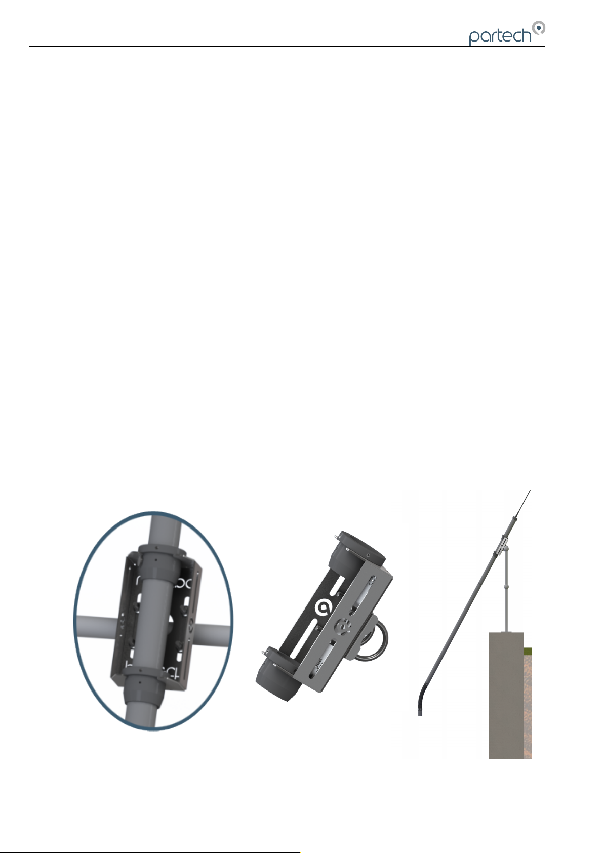
5 Mechanical Installation................................................................................................................................. 10
5.1 Mounting O tions................................................................................................................................. 10
5.2 Mounting Shaft..................................................................................................................................... 10
5.3 Handrail and Wall Brackets.................................................................................................................. 11
5.4 Customer Su lied Brackets............................................................................................................... 11
6 Electrical Installation.................................................................................................................................... 12
6.1 Electrical Installation............................................................................................................................ 12
6.2 Sensor Connections............................................................................................................................ 12
6.3 Extending Sensor Cables.................................................................................................................... 13
7 Sensor Configuration................................................................................................................................... 14
7.1 Sensor Config...................................................................................................................................... 14
7.2 Sensor Status...................................................................................................................................... 14
7.3 Add Sensor.......................................................................................................................................... 14
7.4 S:0x OxyTechw² GAL.......................................................................................................................... 14
7.4.1 S:0x Info....................................................................................................................................... 15
7.4.2 S:0x Remove............................................................................................................................... 15
7.4.3 S:0x Modbus Address.................................................................................................................. 15
8 Measurement Configuration......................................................................................................................... 16
8.1 Measurement Config............................................................................................................................16
8.2 Measurement Status............................................................................................................................ 16
8.3 Add Measurement............................................................................................................................... 16
8.4 M:0x – Measurement Channel............................................................................................................. 17
8.4.1 M:0x Info...................................................................................................................................... 17
8.4.2 M:0x Title..................................................................................................................................... 17
224083IM-Issue 04 20/03/2018 Page 3 of 28

OxyTechw² GAL Instruction Manual
8.4.3 M:0x Set Cal (100.0 %SAT) or M:0x Set Cal (25.0 ºC)................................................................17
8.4.4 M:0x Averaging............................................................................................................................ 17
8.4.5 M:0x Remove............................................................................................................................... 17
8.4.6 M:0x Dis lay Position..................................................................................................................17
8.4.7 M:0x Restore Defaults................................................................................................................. 17
8.4.8 M:0x Set Pressure....................................................................................................................... 18
8.4.9 M:0x Set Salinity.......................................................................................................................... 18
9 Calibration and Testing................................................................................................................................ 19
9.1 Tem erature........................................................................................................................................ 19
9.1.1 Overview...................................................................................................................................... 19
9.1.2 Calibrate Tem erature................................................................................................................. 19
9.2 OxyTechw² GAL.................................................................................................................................. 20
9.2.1 Zero Calibration (Service Mode Only)..........................................................................................20
9.2.2 Zero Checking.............................................................................................................................21
9.2.3 SPAN Calibration.........................................................................................................................21
10 Maintenance.............................................................................................................................................. 22
10.1 General cleaning................................................................................................................................ 22
10.2 Ins ection.......................................................................................................................................... 22
10.3 OxyTechw² GAL Refurbishment........................................................................................................ 22
11 S ares....................................................................................................................................................... 24
12 Technical Su ort...................................................................................................................................... 25
12.1 Returning Equi ment for Re air........................................................................................................ 25
13 Technical S ecification – OxyTechw² GAL................................................................................................26
13.1 Physical............................................................................................................................................. 26
13.2 Electrical............................................................................................................................................ 26
13.3 Measurement..................................................................................................................................... 26
13.4 Mounting O tions............................................................................................................................... 26
Page 4 of 28 224083IM-Issue 04 20/03/2018

OxyTechw² GAL Instruction Manual
1 Foreword
The OxyTechw² Sensor has been s ecifically designed for use with the 7300w² Monitor.
The OxyTechw² GAL Sensor has been designed to rovide highly reliable Dissolved Oxygen measurements
and em loys the traditional galvanic rinci le. The rugged 100 micron, HDPE membrane has been selected
to rovide exce tional resistance to damage. This, combined with Oxyguard's unique electrolyte and anode
material rovides long term stability of 3 years and longer without the need for sensor refurbishment or
membrane re lacement.
For installations in activated sludge lants (ASP's), we recommend that the sensor is installed using our
s ecially designed mounting system, with a flexible joint in the mounting shaft. The flexible joint moves the
sensor in the rocess, kee ing the membrane clean by reducing bio-fouling without the use of a com ressor
and with the added benefit of allowing rags to fall away from the assembly. This motion is similar to that
achieved by using a floating ball assembly, with the added advantage of lacing the sensor below the
surface of the liquor. This means that the sensor is below the level of the floating fats and greases that
accumulate at the surface and results in the Dissolved Oxygen reading being more re resentative of the
whole tank.
The OxyTechw² Sensor rovides the reliable, accurate measurement that is required to o erate activated
sludge lants at the o timum Dissolved Oxygen concentration, maintaining the balance between the running
costs of blowers and aerators and the need to roduce high quality effluent.
224083IM-Issue 04 20/03/2018 Page 5 of 28
OxyTechw² GAL Sensor

OxyTechw² GAL Instruction Manual
2 Introduction
2.1 Manual Conventions
All dimensions stated in this manual are in millimetres unless otherwise stated.
The manual has been written assuming the user has a basic knowledge of instrumentation and an
understanding of the ty e of measurement being made. Training in the use of the 7300w² Monitor and
sensors can be rovided, lease contact Partech for further information.
Icons have been used throughout this manual to draw your attention to recautions and useful notes.
They are categorised in the following way-
GENERAL NOTES – General notes of interest to the user.
GENERAL CAUTION – Used where caution is required to revent injury, damage, corru tion of
data, loss of calibration or invalidation of warranty etc.
INSTALLATION NOTES – General installation notes of interest to the installer.
ELECTRICAL CAUTION – Used where there is a danger of electric shock to the installer or end
user, or where caution is required to revent damage to the instrument.
MAINTENANCE NOTES – Used to highlight recommended maintenance rocedures and hel with
fault finding.
ENVIRONMENTAL NOTES – General notes on environmental issues, waste and dis osal.
2.2 WaterWatch² Trademark
WaterWatchw² is the family name for the w² range of Monitors and sensors. Sensors and instruments
designed for s ecific use with the 7300w² Monitor will be suffixed with the w² trademark.
2.3 cope of Manual
This manual describes the installation, configuration, testing and o eration of the OxyTechw² Sensor. Please
refer to 7300w² Monitor manual for standard functions of the 7300w² Monitor.
2.4 External ensors
External sensors refers to any sensors or instruments connected to the 7300w² Monitor.
Page 6 of 28 224083IM-Issue 04 20/03/2018

OxyTechw² GAL Instruction Manual
3 afety Precautions
3.1 General
Read the safety recautions carefully.
Check the delivery of your WaterWatch² sensor for damage. Any damage should be re orted to your su lier
as soon as ossible.
Use care when un acking the sensor. NEVER use shar instruments to o en the ackaging, as this can
cause damage to the sensor or cable.
Only use accessories s ecifically manufactured by Partech for use with this sensor.
Read the o erating instructions carefully before installing and o erating this sensor.
Kee the cable connections dry and free from contamination during installation.
Kee the sensor away from high voltage cables.
3.2 Electrical installation
Only suitably qualified ersonnel or com etent erson may install, o erate or re air this equi ment.
Please check the sensor has been terminated correctly. Incorrect termination may causes damage to the
sensor or monitor.
The WaterWatch² family of sensors are designed exclusively for use with the 7300w² Monitor. DO NOT
connect to other monitors.
Sensors need to be correctly addressed to the monitor before use. Please read the Quick Start and
Advanced Configuration sections of this manual for full details.
3.3 Operating
Because these sensors have a wide range of a lications, users must acquire the a ro riate knowledge to
use these sensors in their s ecific a lication.
Partech are always available to rovide advice and assistance in your a lication. Please contact Partech for
further information.
These sensors must be correctly calibrated before use. Please read the Advanced Configuration sections of
this manual for full details of calibration rocedures.
3.4 ervice and Maintenance
Before maintenance, this equi ment must be isolated or disconnected from HAZARDOUS LIVE voltages
before access.
Maintenance instructions for the OxyTechw² Sensor should be carried out as s ecified in this instruction
manual. Failure to carry out regular maintenance could invalidate the Warranty.
Services and re airs must be carried out by a Partech engineer. Partech can rovide a service contract for
your system. Please ask for details.
224083IM-Issue 04 20/03/2018 Page 7 of 28

OxyTechw² GAL Instruction Manual
3.5 End of Life Disposal
Equi ment should be recycled according to local regulations.
Any calibration solutions should be dis osed of as described in the Manufacture Safety Data Sheet
accom anied with the calibration solution.
Partech can rovide recycling and dis osal of your old Partech equi ment, and may also rovide the same
service for other manufactures equi ment when re laced with Partech equi ment.
Partech may rovide a trade-in o tion for new equi ment. Please contact Partech for further information.
Page 8 of 28 224083IM-Issue 04 20/03/2018

OxyTechw² GAL Instruction Manual
4 OxyTechw² GAL ensor
Whilst every attem t has been made to ensure that these instructions are correct, common sense and good
engineering ractice should always be used, as every installation can resent a new set of challenges and
difficulties. If you are in any doubt lease contact Partech or your local distributor for further information.
4.1 ensor Overview
The OxyTechw² GAL Sensors a galvanic oxygen sensor. It has an u er art with Cathode, Anode and
cable, and a lower art with membrane and and electrolyte. It roduces a tem erature com ensated millivolt
electrical out ut ro ortional to the oxygen artial ressure it senses. It also roduces a se arate
tem erature out ut for the 7300w² monitor to dis lay.
The OxyTechw² GAL Sensor is hermetically sealed, however, the bottom screw on membrane ca can be
o ened for electrolyte maintenance or to re lace the membrane should this be required. The to ca at the
cable entry end should not be o ened as it contains no user serviceable arts.
The measurement stability of the OxyTechw² GAL Sensor is very high. A robe measuring in air will maintain
accuracy even when subjected to a sudden 20º C tem erature change. The sensitivity of a robe measuring
in clean air at room tem erature will remain the same for at least 3 years, therefore it is not effected by
ageing as with other sensors, reducing the o erating cost and the need for intensive maintenance. A well
maintained sensor can have a life of 8 years without a membrane change.
4.2 torage
When not in use the sensor should be stored with its yellow rotective ca in lace over the sensor
membrane. For very long term storage, over twelve months, it is advisable to remove the electrolyte, rinse
and dry the sensor and store in this dry condition.
224083IM-Issue 04 20/03/2018 Page 9 of 28
Sensor
Identification
Serial
Number
Screw on
Membrane Ca
for refurbishment
ModTechw²
Cable

OxyTechw² GAL Instruction Manual
5 Mechanical Installation
Reliable accurate measurement from any instrument can only be achieved by correct installation of the
measuring device; in the case of the OxyTechw² Sensors, this is articularly im ortant. If you are in
any doubt contact Partech or your local distributor for advice.
Below are some oints that should be considered before starting to install the sensor, or in the event
an installed sensor gives unreliable measurements-
•Ensure that the sensor is immersed dee ly enough into the sam le.
•The sensor should be mounted in such a way as to allow easy access for calibration and
maintenance. It should be ossible to remove the sensor from the rocess without the need to shut
the rocess down.
•The sensor must be monitoring a sam le of the rocess that is re resentative of the whole rocess.
•To allow a single technician to calibrate and maintain the system the sensor should be laced within
sight of the 7300w² Monitor. Although cable runs of u to 100 metres are ossible o erational
roblems can be caused.
•The OxyTechw² GAL Sensor should NOT be mounted with the membrane facing u .
•Where ossible, angle the sensor so that it is ointing down stream, this will allow any “ragging” to
be removed by the flow ast the sensor.
•Do not install where there is a likelihood of freezing.
5.1 Mounting Options
Partech offer a range of mounting brackets for the installation of the OxyTechw² Sensor, which will allow the
user to a ly the sensor in a wide variety of locations. Drawings of the brackets are shown in the relevant
“O tional Accessories” sections of this manual. When assessing mounting o tions, attention should be aid
to the accessibility of the sensor for calibration and maintenance, stability of the sensor in the flow conditions
resent on site and to ensuring the sensor is fully submerged at all times.
5.2 Mounting haft
An o tional mounting shaft fitting can be used to allows the OxyTechw² Sensorsto be fitted to a number of
mounting accessories. Partech su ly mounting shafts manufactured from 2” nominal bore grey ABS i e in
Page 10 of 28 224083IM-Issue 04 20/03/2018

OxyTechw² GAL Instruction Manual
0.5, 1.0, 1.5, 2, 2.5 and 3.0 metre lengths. Whilst other lengths can be rovided as s ecial orders, generally
standard lengths will satisfy most requirements. It should be noted that sensors with long mounting shafts
are difficult to move safely and can resent roblems with calibration and maintenance, shaft lengths should
be ke t to a minimum where ossible.
5.3 Handrail and Wall Brackets
The mounting shafts described above need to be attached to the structure of the tank or flow channel where
measurement is required. The mounting shaft sits inside the mounting bracket and is located using locking
collars. To remove the mounting shaft, remove the locking thumb screw and lift the shaft from the bracket.
Care should be taken to ensure that the sensor can be reached from the walkway to allow removal for
calibration and maintenance.
5.4 Customer upplied Brackets
When creating brackets to mount the OxyTechw² Sensor, care should be taken to ensure that the
following guidelines are observed:
•The bracket must be strong enough to su ort the sensor with minimum movement when installed
into the sam le.
•The sensor should be fitted by clam ing around the sensor body or sus ended by the cable.
•Consideration should be given to enable sim le removal and re lacement of the sensor for
ins ection, calibration and servicing to be carried out.
224083IM-Issue 04 20/03/2018 Page 11 of 28

OxyTechw² GAL Instruction Manual
6 Electrical Installation
6.1 Electrical Installation
Unscrew the two cover screws on the lower anel of the 7300w² Monitor to reveal the Terminals. Each
terminal stri is labelled as illustrated below. (This equi ment must be isolated or disconnected from
HAZARDOUS LIVE voltages before access). Refer to the 7300w² Monitor user manual for full descri tion of
all the terminals within the monitor.
The maximum size wire that can be terminated is 2.5mm² CSA. All the connections are via removable
Plug/Socket terminals. To disengage the terminal stri , sim ly ull down to release.
6.2 ensor Connections
When routing the sensor cables, lease ensure the cable is se arated from any mains cables. Although the
Partech w² sensors have a high resistance to interference, se aration of mains and data cables is good
ractice and should always be followed where ractical.
All sensors in the w² range communicate with the monitor using the ModTechw² Protocol. This rotocol has
been s ecifically designed to take advantage of the advanced features and diagnostics designed into the w²
range of sensors.
Note- These sensors can NOT be used with other monitors that are not
included in the w² family.
All sensors within the w² family of instruments are connected to the
7300w² Monitor using the same 4 wire configuration.
•RED and BLACK wires rovide the 12VDC su ly to the sensor.
•WHITE and GREEN rovide data communication.
A maximum of two sensors can be directly connected to the standard
7300w² Monitor, additional sensors can be added using the o tional
ex ansion boxes available se arately.
Remove the 4-way connector from the 7300w² Monitor by ulling downwards to disconnect for easy access
to the connections. Connect the sensor wires as follows-
(Terminals from left to right on the 4 way connector)
Term 1 (Left) - RED (+12V)
Term 2 - Black (0V)
Term 3 - White (Data A)
Term 4 (Right) - Green (Data B)
Always connect the screen drain wire with the Black (Term 2).
Always use Bootlace ferrules when terminating the sensors to ensure a good connection
to the terminals.
Page 12 of 28 224083IM-Issue 04 20/03/2018

OxyTechw² GAL Instruction Manual
6.3 Extending ensor Cables
Sensors are usually su lied with 10M cables (longer cables can be rovided if requested). These cables
can be extended to a maximum length of 100M. To ensure o timum erformance, only use Partech
ModTechw² cable for extensions. Partech can su ly junction boxes to allow for cable extensions. These
should be used on all installations where the cable length from the sensor to the monitor exceeds 20M
(Partech Junction boxes include on-board filtering for long cable lengths). Junction boxes are also useful for
local connection of sensors close to the sam le oint. This allows for easy re lacement of sensors without
the need to ull back cables to the monitor. The junction box has an on-board terminator switch that can be
activated to terminate the network if the sensor is to be removed for long eriods.
When joining cables, ensure the connection is fully water roof. Any moisture ingress can effect the
communication between the sensor and monitor.
ModTechw² Cable s ecification-
•2 Twisted Pair - Red/Black (Power) and Green/White (Data) with Screen and Drain wire
•Cores 24AWG (0,22mm²) 7 x 0,20mm
•Outer Insulation – PUR Polyurethane Blue (RAL5003), Diameter - 5mmØ
224083IM-Issue 04 20/03/2018 Page 13 of 28

OxyTechw² GAL Instruction Manual
7 ensor Configuration
Before attem ting to configure the sensor, lease read the monitor user
manual that came with your monitor. The monitor manual will introduce
you to the basic set-u of the monitor, and will familiarise you with the
monitor menu structure and buttons.
The monitor leaves the factory with no sensors re-installed.
Assuming the monitor has been hysically connected to a sensor, the
next ste is to register and configure the sensor before any measurements can be made. A single sensor
may rovide one or more measurements. We advise only connecting one sensor at a time. Once the first
sensor has been registered, connect the second and register again. Re eat for any additional sensors.
All sensors must be registered to the monitor in this way, even if they are different ty es.
7.1 ensor Config
From the MAIN MENU screen, select SENSOR CONFIG using the
arrow button, and ress .
7.2 ensor tatus
This o tion allows the user to review the current status of the 8 sensor
channels, these will all be set to disabled until a sensor is added.
Once a sensor has been installed the dis lay will be u dated to indicate the sensor ty e installed and
it's status.
7.3 Add ensor
1. From the MAIN MENU screen, select SENSOR CONFIG by
ressing , and ress .
2. The SENSOR MENU should be dis layed. Press to
highlight ADD SENSOR, and ress .
3. The Monitor will now search all ossible addresses (0 to 240)
to find any attached sensors. During the search, any sensors
found will be dis layed momentary before continuing with the
search.
4. Once the search is com lete, the Monitor will dis lay a list of sensors found. Each sensor will be
automatically allocated a new address from S:01 to S:08.
5. Re eat the above rocess to install a second, third or more sensors. A total of 8 sensors are
ossible (ex ansion box may be required to add additional sensors).
6. Sensor addition is now com lete.
7. If a single or multi le sensors have been found the can be
ressed to esca e from continuing the search.
7.4 :0x OxyTechw² GAL
Once the sensor has been added and registered, the monitor will rovide a
list of functions s ecific to the sensor. Press or to select the sensor
and ress . The CONFIG MENU will dis lay a list of sensor functions.
Page 14 of 28 224083IM-Issue 04 20/03/2018
MAIN MENU
Monitor Config
Expansion Config
ensor Config
Measurement Config
Alarm Config
Output Config
Information
SENSOR CONFIG
ensor tatus
Add ensor
<No ensors Installed>
SENSOR CONFIG
ensor tatus
Add ensor
:01 OxyTechw2 GAL
M:01 %SAT
87.4
DISSOLVED OXYGEN
Monitor: OK 09:59:45 17/05/12

OxyTechw² GAL Instruction Manual
7.4.1 :0x Info
This function rovides a range of diagnostic information that may be
requested by Partech for fault finding.
7.4.2 :0x Remove
This allows the sensor to be removed for re-configuration of the monitor or
if a sensor has been added in error. If a sensor has been re laced with a
new sensors, the old sensor must be removed, and the new sensor
installed. If a sensor (in a multi le configuration) is no longer required, all traces from the menus can
be removed.
You will be rom ted with 'Are you sure?' before the sensor is removed. Press to acce t and
remove.
7.4.3 :0x Modbus Address
This o tion allows manual adjustment of the ModTechw² address for the sensor, under normal
circumstances this should not be changed
224083IM-Issue 04 20/03/2018 Page 15 of 28
CONFIG
:01 Info
:01 Remove
:01 Modbus Address

OxyTechw² GAL Instruction Manual
8 Measurement Configuration
The monitor leaves the factory without any measurements configured. Measurements will only be
available after installing the relevant sensor(s).
Once the sensor(s) have been registered with the monitor and installed, the measurements will now be
available.
8.1 Measurement Config
From the MAIN MENU screen, select MEASUREMENT CONFIG by
ressing , ress . The screen shot to the left shows the default
configuration after the installation of the OxyTechw² sensor on a single
sensor configuration:
M:01 = %SAT; M:02 = mg/l; M:03 = Tem erature.
8.2 Measurement tatus
This o tion allows the user to review the current status of the 16 measurement channels, these will all
be set to disabled until a sensor is added. In the exam le above the first three measurement channels
will be enabled.
Once a measurement has been configured the dis lay will be u dated to indicate the measurement
and it's status.
8.3 Add Measurement
This o tion allows the user to add extra measurements available from the current sensor installation.
i.e. One sensor may contain multi le measurements. In the screen shot above the default installation
for the OxyTechw² sensor shows: M:01 Dissolved Oxygen %SAT, M:02 Dissolved Oxygen mg/l, &
M:03 Tem erature. There is one extra measurement that could be added to this list for the OxyTechw²
sensor, and that is Dissolved Oxygen PPM. To add this measurement the following should be a lied.
1. The MEASUREMENT MENU should be dis layed. Press to
highlight ADD MEASUREMENT, and ress .
2. All available measurements will be dis layed in a list. Press or
to select the required measurement.
3. Press to select the measurement. Re eat the rocess if more
measurements are required.
4. Each measurement will be allocated a measurement number from
M:01 – M:16. A total of 16 measurements may be dis layed.
5. Press to return back to the dis lay screen. Your measurement
addition should now be dis layed. If more than one measurements
were configured, ress to cycle through the dis lay screen to
show the measurements, The screen shot on the left shows the
additional measurement M:04 which is Dissolved Oxygen PPM.
The Measurement Menu will list all configured measurements in order M:01 to M:16 the list will also
indicate the sensor number that is delivering the signal for the measurement. Any ermutation of
measurements can be configured. It is not necessary to have all four measurements enabled.
IMPORTANT: The rimary measurement for the OxyTechw² GAL sensor is %SAT. This is the
measurement that will be used for calibration ur oses. The other measurements are derived from this
reading lus the tem erature measurement.
Page 16 of 28 224083IM-Issue 04 20/03/2018
MEASUREMENT CONFIG
Measurement tatus
Add Measurement
M:01 Dissolved Oxygen ( :01)
M:02 Dissolved Oxygen ( :01)
M:03 Temperature ( :01)
MEASUREMENT CONFIG
Measurement tatus
Add Measurement
M:01 Dissolved Oxygen ( :01)
M:02 Dissolved Oxygen ( :01)
M:03 Temperature ( :01)
MEASUREMENT CONFIG
Measurement tatus
Add Measurement
M:01 Dissolved Oxygen ( :01)
M:02 Dissolved Oxygen ( :01)
M:03 Temperature ( :01)
M:04 Dissolved Oxygen ( :01)

OxyTechw² GAL Instruction Manual
8.4 M:0x – Measurement Channel
Selecting a measurement channel will reveal a new sub-menu associated
with that measurement. In MEA UREMENT CONFIG ress to highlight
the required measurement and ress .
The sub-menu is as follows:
In M:0x CONFIG ress to highlight the required function and ress .
8.4.1 M:0x Info
This o tion rovides multi le ages of additional information and
diagnostics on the measurement. This information will only be required if a
roblem exists with the instrument erformance.
8.4.2 M:0x Title
Important Note: This o tion is not available on the Temperature
measurement.
This allows the title of the measurement to be changed from it's default, the measurement title is used
in measurement mode to identify the measured value. A selection of standard terms are available
along with a 'User Defined' o tion that can be adjusted to suit your requirements. For exam le this
could be changed to 'DO – Lane 1'. The maximum number of characters is 20.
8.4.3 M:0x et Cal (100.0 % AT) or M:0x et Cal (25.0 ºC)
Important Note: This o tion is only available on the %SAT measurement and Temperature
measurement channels. %SAT is the rimary measurement associated with Dissolved Oxygen.
Therefore this is the only Dissolved Oxygen measurement ca able of direct calibration.
The calibration of the system is covered in a se arate section below.
8.4.4 M:0x Averaging
Important Note: This o tion is only available on the %SAT measurement.
This allows the user to im ose averaging on the measured value, this is used to reduce the s eed of
reaction to the rocess changes. The value can be adjusted between 0 and 6000, the higher the value
the slower the reaction time.
8.4.5 M:0x Remove
This allows the user to remove a measurement that has been selected in error or to allow re-
configuration of the system. Please use this o tion with care, all user settings will be lost if the
measurement is removed in error.
8.4.6 M:0x Display Position
This o tion allows the osition of the measurement to be moved. For exam le the Tem erature
measurement can be changed from M:03 to M:02 so it will a ear second on the list in
MEASUREMENT CONFIG menu.
8.4.7 M:0x Restore Defaults
This returns all the selected measurement settings back to the factory
defaults for that articular arameter. Caution should be exercised when
using this feature as all user defined settings and calibration associated with
that measurement will be lost and reset to their default values.
Important Note: This o tion is only available on the %SAT & Temperature
measurement.
224083IM-Issue 04 20/03/2018 Page 17 of 28
M:01 CONFIG
M:01 Info
M:01 Title
M:01 et Cal (100.0 % AT)
M:01 Averaging
M:01 Remove
M:01 Display Position
M:01 Restore Defaults
M:01 CONFIG
M:01 Info
M:01 Title
M:01 et Cal (100.0 % AT)
M:01 Averaging
M:01 Remove
M:01 Display Position
M:01 Restore Defaults
MEASUREMENT CONFIG
Measurement tatus
Add Measurement
M:01 Dissolved Oxygen ( :01)
M:02 Dissolved Oxygen ( :01)
M:03 Temperature ( :01)
M:04 Dissolved Oxygen ( :01)

OxyTechw² GAL Instruction Manual
8.4.8 M:0x et Pressure
Important Note: This o tion is only available on the mg/l or PPM
measurement.
This o tion allows the user to set a fixed ressure value in mbar within the
mg/l or PPM measurements to com ensate the Dissolved Oxygen reading
for changes in ressure in the environment of the sensor.
8.4.9 M:0x et alinity
Important Note: This o tion is only available on the mg/l or PPM measurement.
This o tion allows the user to set a fixed salinity value in t within the mg/l or PPM measurements to
com ensate the Dissolved Oxygen reading for changes in salinity in the environment of the sensor.
Page 18 of 28 224083IM-Issue 04 20/03/2018
M:01 CONFIG
M:01 Info
M:01 Title
M:01 Remove
M:01 Display Position
M:01 et Pressure
M:01 et alinity

OxyTechw² GAL Instruction Manual
9 Calibration and Testing
9.1 Temperature
9.1.1 Overview
As already mentioned the OxyTech2² GAL sensor has two integral tem erature measurements. The
first measurement is not dis layed and is used solely to com ensate for tem erature fluctuations in the
measurement solution across the membrane. It roduces a stabilised millivolt electrical out ut
ro ortional to the oxygen artial ressure it senses. The other tem erature measurement is
transmitted back to the 7300 monitor and is used to:
1) Dis lay tem erature.
2) Com ensate for changes in saturation reading due to tem erature, by referencing the reading to a fixed
tem erature value.
3) Calculating the solubility of the solution in mg/l.
Once the tem erature has been calibrated there should be no reason to re-calibrate as the
measurement is inherently stable and will not change over time. The accuracy of the reading de ends
on the sensor head equilibrating with tem erature. Thus the sensor element buried within the body of
the sensor becomes re resentative of the true tem erature in the surrounding environment.
The tem eratures integrity can be checked at any time by com aring it with a known tem erature
reference after a eriod of tem erature equilibration. If for any reason the tem erature is deemed to be
inaccurate or needs to be different from the settings as carried out in the factory, then the following
rocedure may be a lied.
9.1.2 Calibrate Temperature
From the 7300w² Monitor, navigate to the Calibration menu as follows:
1. Ensure that the sensor head, whether in or out of solution has been
in a constant tem erature environment for at least 20 minutes
before commencing this o eration. Ensure that the reference
measurement tool, e.g. thermometer is also suitably tem erature
equilibrated.
2. Press to show the “MAIN MENU”.
3. Select “MEASUREMENT CONFIG” by ressing and ress
.
4. Select “TEMPERATURE” by ressing and ress .
5. Select “SET CAL” by ressing ress .
6. The sensor information screen will be dis layed. Press to move
on.
224083IM-Issue 04 20/03/2018 Page 19 of 28
MEASUREMENT CONFIG
Measurement tatus
Add Measurement
M:01 Dissolved Oxygen ( :01)
M:02 Dissolved Oxygen ( :01)
M:03 Temperature ( :01)
M:04 Dissolved Oxygen ( :01)
M:03 CONFIG
M:03 Info
M:03 et Cal (25.0 ºC)
M:03 Remove
M:03 Display Position
M:03 Restore Defaults
M:03 SET CAL (25.0 ºC)
CALIBRATE MEA UREMENT
M:03 temperature
:01 OxyTechw2 GAL
N: 400001
Last Calibrated: 01/01/1970 00:00:00
By:
Press OK to contiue or MENU to Exit

OxyTechw² GAL Instruction Manual
7. The “SET CAL” screen will be dis layed. Using the arrow keys set
the tem erature value the same as is dis layed on your tem erature
reference tool. Press to acce t. The Calibration screen will now
be dis layed.
8. Wait for the value to stabilise (The digits should not be changing),
then ress to acce t.
The tem erature calibration is now com lete.
9.2 OxyTechw² GAL
The OxyTech2² GAL sensor is very stable and will maintain its calibration for extended eriods of time,
the rimary reason for a change in the calibration is the resence of a bio-film on the membrane. The
design of the sensor means that zero oint testing is not required. We recommend that calibration is
carried out during commissioning and is then checked after one weeks o eration. Following this
calibration should be carried out after 3 months. At this time ongoing calibration frequency can be
determined. This would normally be every 6 months.
9.2.1 Zero Calibration ( ervice Mode Only)
NOT : This is the only advanced S RVIC Mode function shown in this manual.
This o tion will not be available unless 'Service Mode' is set on the 7300 monitor. Therefore, a zero
calibration is NOT generally required for the OxyTech2² GAL sensor as this has been done in the
factory.
The zero value used is a true electrical zero and is achieved without any electrolyte resent in the
sensor. If during sensor refurbishment it is connected to the 7300 monitor without the electrolyte filling
solution resent, the reading dis layed will check the integrity of the sensor and whether there has
been water ingress into the electrode or cable assembly. If there is a ositive reading of 1% or more,
then the sensor should be discarded and re laced as water ingress has occurred.
If an electrical zero calibration is required then the following should be ado ted.
The sensor will be dismantled with no electrolyte resent. The internal anode
should be clean and dry. (See sensor refurbishment below for details)
Enable 'Service Mode' . (See 7300w² instruction Manual)
From the 7300w² Monitor, navigate to the Calibration menu as follows-
1. Press to show the “MAIN MENU”.
2. Select “MEASUREMENT CONFIG” by ressing and ress .
3. Select “DISSOLVED OXYGEN” by ressing and ress .
NOTE: This will be the first DISSOLCED OXYGEN o tion as the
second relates to mg/l solubility, and there is no calibration o tion for
this measurement.
Page 20 of 28 224083IM-Issue 04 20/03/2018
M:03 SET CAL (25.0 ºC)
25.0 ºC
Use to set value
Press OK to accept
Press MENU to cancel
M:03 SET CAL (25.0 ºC)
Insert sensor into calibration
solution and wait for measurement
to stabilise
Press OK to contiue or MENU to Exit
24.9 ºC
SM M:01 CONFIG
M:01 Info
M:01 Title
M:01 et Cal (0.0 % AT)
M:01 Averaging
M:01 Remove
M:01 Display Position
M:01 et Cal (100.0 % AT)
SM MEASUREMENT CONFIG
Measurement tatus
Add Measurement
M:01 Dissolved Oxygen ( :01)
M:02 Dissolved Oxygen ( :01)
M:03 Temperature ( :01)
M:04 Dissolved Oxygen ( :01)
Trend Download
Table of contents
Other ParTech Accessories manuals
Popular Accessories manuals by other brands

DOUXE
DOUXE S3 Active Stylus Pen instruction manual

FirstHealth
FirstHealth FH7020 instruction manual

Seav
Seav WiWeather S/F 433 manual

Honeywell Home
Honeywell Home DC311 Series manual

ROSE DISPLAYS
ROSE DISPLAYS SNAIL ADHESIVE-GENERIC installation instructions

Focusrite
Focusrite Clarett 2Pre USB user guide