PASCOR ATLANTIC DR7 User manual

IB-DR7-A
May, 2012

1 | Page
Contents
Subject Page
Receiving and Handling . . . . . . . . . . . . . . . . . . . . . . . . . . . . . . . . . . . . . . . . . . . . . . . . 2
Installation and Adjustment
Step 1. Check Bases . . . . . . . . . . . . . . . . . . . . . . . . . . . . . . . . . . . . . . . . 2
Step 2. Assemble Insulators . . . . . . . . . . . . . . . . . . . . . . . . . . . . . . . . . . 3
Step 3. Insulator Stack Alignment . . . . . . . . . . . . . . . . . . . . . . . . . . . . . 3
Step 4. Mount Current Carrying Parts . . . . . . . . . . . . . . . . . . . . . . . . . 4
Step 5. Switch Blade Adjustment . . . . . . . . . . . . . . . . . . . . . . . . . . . . 4
Step 6. Mount Switches . . . . . . . . . . . . . . . . . . . . . . . . . . . . . . . . . . . . 4
Step 7. Mount Offset Bearing . . . . . . . . . . . . . . . . . . . . . . . . . . . . . . . . 4
Step 8. Adjust Multi-Angle Crank . . . . . . . . . . . . . . . . . . . . . . . . . . . . . 5
Step 9. Install Interphase Rods and Offset Crank Rod . . . . . . . . . . . . . . 5
Step 10. Install Vertical Operating Pipe . . . . . . . . . . . . . . . . . . . . . . . . . 6
Step 11 Install Pipe Splice and Guide Plate . . . . . . . . .. . . . . . . . . . . . . . . 6
Step 12. Install Operating Mechanism . . . . . . . . . . . . . . . . . . . . . . . . . . . 6
Step 13. Arcing Horn Instillation . . . . . . . . . . . . . . . . . . . . . . . . . . . . . . . . 7
Step 14. Installation of Corona Rings and Balls . . . . . . . . . . . . . . . . . . . . . 8
Step 15. Final Checks . . . . . . . . . . . . . . . . . . . . . . . . . . . . . . . . . . . . . . . . . 8
Terminal Connections . . . . . . . . . . . . . . . . . . . . . . . . . . . . . . . . . . . . . . . . . . . . . . . . . . . . 8
Maintenance . . . . . . . . . . . . . . . . . . . . . . . . . . . . . . . . . . . . . . . . . . . . . . . . . . . . . . . . . . . 8
Bearings . . . . . . . . . . . . . . . . . . . . . . . . . . . . . . . . . . . . . . . . . . . . . . . . . . . . . . . 9
Renewal Parts . . . . . . . . . . . . . . . . . . . . . . . . . . . . . . . . . . . . . . . . . . . . . . . . . . . . 10
Lubrication . . . . . . . . . . . . . . . . . . . . . . . . . . . . . . . . . . . . . . . . . . . . . . . . . . . . . . . 10
Suggested Tools
•15/16” Open-End Wrench
•15/16” Socket
•3/4” Open-End Wrench (2)
•3/4” Socket
•1 1/2” Open-End Wrench or Adjustable
•Lineman Pliers
•Tape Measure
•Angle Finder
•Metal Cutting Saw
•Level

2 | Page
Leveling Screws
Shims Used for Leveling Switches
Shims (As Reqired)
Base Channel Flange
Rotor or Spacer Base
Leveling Screw
Rotor or Spacer Base
Base Channel Flange
Fig. 1 Types of Leveling Devices
Leveling Bolts
Rotor or Spacer Base
Base Channel Flange
Adjusting Nuts
Taper Washer
(When Used)
Taper Washer
(When Used)
Taper Washer
(When Used)
IMPORTANT: Read manual before installing or maintaining equipment! Make absolutely sure that
equipment is de-energized and properly grounded.
This manual should be used in conjunction with the factory drawings. The drawings contain critical
information, which if not followed could affect the operation of the switch.
Instructions can not cover all possible variations in equipment nor provide for every possible contingency
to be met in connection with installation, operation or maintenance. Should further information be
required or should particular problems arise which are not covered sufficiently for the purchaser’s
purposes, the concern should be referred to the factory.
For Technical Assistance Call 276-688-3328
RECEIVING INSPECTION
Check the shipment for completeness against the
bill of material and installation drawings. If
damage is found, file a claim immediately with
the transportation company and notify your
Pascor Atlantic representative.
HANDLING
Handling of disconnect switches should be done
with care. Porcelain is fragile and may be
damaged due to improper handling.
Factory drawings should be followed during
installation. It is recommended that switches be
fully assembled and adjusted at ground level
before being placed into position. This should
minimize final adjustments.
Lifting of switches by insulators, contacts, or
live parts should be avoided, because of possible
damage to these parts. Attachments for hoisting
should be made to the switch bases unless
otherwise instructed.
CAUTION: When uncrating switches having
blade counterbalances open the switch blade
to relieve the pressure of the counter balance
before removing the live parts from the base.
INSTALLATION AND ADJUSTMENT
If the switches have already been assembled
with insulators at the factory, proceed to step 5.
However, it is recommended that each switch
pole be checked for alignment and proper
adjustment after being mounted on the structure.
Step 1—Check Bases
Check bases to make sure that the spacers and
rotor bearing tops are square and level. The tops
of the two supports on the hinge end must be
exactly the same height. If necessary, make
adjustments or shim. Shims, leveling screws,
and adjusting nuts are shown in Fig. 1 and are
explained in step 3.

3 | Page
Step 2—Assemble Insulators
In some cases, involving higher voltage
switches, the installer may choose to mount the
switch bases on the structure before assembling
the insulators. In such cases the switch bases
should be mounted on the supporting structure in
the positions shown on the installation drawing.
Verify that the base for the drive phase is in the
correct location and operating cranks are at their
proper angles. Working on one end of the switch
base at a time remove the bolts holding the
switch cranks to the head of the rotor bearing.
Using these same bolts mount the insulators on
the top of the cranks, being careful not to change
the angular position of these cranks. These
cranks were mounted in the proper position at
the factory and should not be changed.
(Fig 3) shows a typical switch base with the
crank orientation for the switch in the closed
position. The base on the driven phase will
usually contain an additional crank.
Step 3—Insulator Stack Alignment
Lower voltage switches 8.25 thru 72.5kV
generally do not require insulator stack
alignment. Where required, the insulator stacks
of switches thru 242kV can be aligned using
open-end shims or leveling screws and/or
adjusting nuts (Fig. 1) if supplied (optional).
•If using shims, place the shims under the
insulator supports (rotor bearing or spacer
mounting flange) where the bolts secure the
rotor bearing or spacer mounting flange to
the switch bases.
•If optional leveling screws and/or adjusting
nuts have been supplied, as shown in Fig. 1,
adjust the leveling screw and/or adjusting
nut to align the insulator stacks. Loosen all
hardware before jacking to prevent binding.
Step 4—Mount Current Carrying Parts
Refer to fig 3 and with cranks in the switch
closed position, assemble the current-carrying
parts on the insulator stacks with the bolts
provided. Normally, the blade end of the switch
is mounted at the end of the switch, where the
interphase rods are installed. However, the
switch may be operated from the jaw end
Fig. 4 Jaw Contacts
Fig. 3 Typical Set of Base Parts

4 | Page
without any noticeable difference. Refer to
installation drawing for intended of preferred
positioning of jaw and blade end.
Note: The counterbalances are assembled at the
factory for the mounting positions as required
for each installation. If it is necessary to change
the mounting position of the switch in the field,
the counterbalance must be changed as well.
Step 5—Switch Blade Adjustment
In the switch closed position, the moving contact
of the blade should come to rest nearly midway
on the contact portion of the jaw contacts, Fig. 4.
Use the shims or leveling screws (which ever are
furnished) between the base of the rotor bearings
and the switch base, to achieve the proper blade
penetration into the jaw. After this adjustment
the insulator stacks may be slightly out of plumb
when the switches open but well within the
tolerances with the switch closed.
With the switch contacts closed as described
above, the connecting rod should be adjusted so
that there is neither tension nor compression in
the rod. Adjustment may be made by removing
the pin at the attachment point of crack and
clevis, loosening the locknut, screwing the clevis
in or out to adjust the length until the proper
length is obtained. The locknut is then tightened
and final assembly of the pin is made to attach
clevis and crank.
After this has been accomplished, the closed
position stop bolt (A) Fig. 5 is set so that it
engages the mating projection (B) on the crank.
Then, move the switch to the fully open position
and adjust the one position stop bolt (C) in the
same manner.
This procedure applies to each single pole.
Step 6—Mount Switches
Assemble the switches on the supporting
structure in accordance with the positions shown
on the installation drawing. The switches
should be mounted level and parallel with each
other. In case of a warped structure, shimming
under the switch bases may be required.
Step 7—Mount Offset Bearing
For those installations requiring an offset
bearing, mount the offset bearing and its
supporting base on the structure in the position
shown on the installation drawing.Check
operating crank for proper length radius and
Fig. 6 Operating Pole Multi-angle Crank

5 | Page
angle, and stop crank for correct position.
If the offset bearing has an adjustable crank, it is
sometime necessary to add ¼” to ½” to the trial
radius given on the control drawing to get
required travel to switch blades. This additional
length allows for lost motion and clearances in
pin holes and will also provide a definite audible
sound accompanied by a reasonable amount of
deflection in the structural members when the
crank crosses the dead canter position. This
serves as a signal to the operator that the switch
is either fully open or closed.
Step 8—Adjust the Multi-Angle Crank
The crank is identified in Fig. 6. This crank is
supplied in the operation pole unit connected to
the offset bearing. It permits 330˚ angular
adjustments with crank location every 10˚ which
allows adjustments to within 5˚ of desired
position. In some adjustments, the adjustable
crank may be in such a position to interfere with
the stop projection on the switch crank. If this is
the case, remove this projection. The other two
poles will regulate the blade travel on this unit.
The multi-angle crank should be set so that it
forms an angle of approximately 45 degrees with
an offset link in either switch position, closed or
open. On 5” base circle switches the multi-angle
crank is installed on the top of the switch crank,
on 3” base circle switches it is installed on the
bottom.
Step 9—Install Interphase Rods
With all blades in the closed position, install the
interphase rods and offset crank rod as follows:
a. Lengthen the interphase rods that are in
compression during opening, as much as
possible, yet allowing for the pins to be
inserted.
b. On the rods that are in tension during
opening, shorten them as much as possible,
yet allowing for the pins to be inserted.
c. The offset crank rod between the outboard
bearing and the driven switch should be
handled the same way
d. For lubrication of pins and bearing areas, see
Table 2.
Adjustable Clevis
C onnecting Link
Offset BearingRod
R otor Bearing
C oupling
Operating
Pipe
F l e x i b l e G round
S t r ap
Manual
W o r m - Gear
Operator
Pipe Splice
and Pipe
Guide Plate
Supplied Only
When R equired
V e r t i cal
Operating Pipe
H andle C lamp
T e l e s c opic
H andle
Length 3
to 5 Feet
K i r k Key
Interlocking
Interlocking Plate
( O p t i o nal) P r o v i sion
for
Padlocking
Adjustable Lock
Plate w ith Position
Indication
Fig. 8 Standard Offset-Torsional Mechanism on Standard
Support Structure
Fig. 7 Manual Worm Gear Operating Mechanism

6 | Page
Step 10—Install Vertical Operating Pipe
For directly connected switch operating
mechanism, attach vertical operating pipe to switch
rotor bearing shaft. Or, In the case of offset-
torsional operating mechanism, attach vertical
operating pipe to offset rotor bearing shaft, with
coupling and pins supplied. For reference, see Figs.
7 and 8. At this point, check drawings for accessory
equipment (auxiliary switches, mechanical
interlocks, position indicators, ground straps, etc.)
which mounts on vertical operating pipe and install
before continuing installation. The vertical pipe is
predrilled at one end for a 5/8” diameter pin, two of
which are shipped, together with a coupling in a
bag, for connection to the offset bearing shaft (or
on the pole unit rotor bearing in the case of direct
connection switches)
Step 11—Install Pipe Splice and Guide Plate
When the length of the vertical operating
pipe exceeds 23 feet, a pipe splice and a
guide plate are furnished and should be
installed as shown in Fig. 8. The pipe spice
and both pieces of pipe are pre-drilled to
receive the 5/8” diameter pins. The guide
plate should not be solidly mounted until
after the vertical pipe has been completely
installed; then bolts holding the guide plate
on the structure should be tightened in order
that the holes In the guide plate line up with
the normal position of pipe. This assures that
there is no binding.
Step 12—Install Operating Mechanism
Two types of manual operating mechanisms
•Swing-handle operator
•Worm gear mechanism
Fig. 10 Geared Mechanism
Fig. 11 MO-10 Motor Operator
Fig 9. Operating Handle Lock Plate

7 | Page
Swing Handle Operator
To install the swing handle operator:
1. With ground strap in place on vertical
operating pipe, slide handle and handle lock
plate over the end of the vertical operating
pipe
2. Fasten the lock plate at the proper location.
Recommended height for the lock plate is 3
ft. 6 in. above ground.
Note: The lower end of the vertical operating
pipe should extend through the lock plate at
least 3 inches. It may extend as much as 3 feet
or more, just so it doesn’t touch the ground or
column footing.
3. The lock plate assembly (Fig. 9) consists of
two castings, mounted on the pipe guide
plate, which can be easily adjusted in an arc
to provide the required rotation. These act
as locks for the manual operating handle
when it is dropped from the operating
position. The handle must be raised to a
horizontal position for operation.
4. With the switch in the fully closed position,
set the handle clamp so its set screws are 4
inches above the lock plate and its vertical
centerline is at or near as possible to the
closed position, see Fig. 8.
5. Temporarily fasten the handle to the pipe
with the set screws.
Worm Gear Mechanism
1. With ground strap in place on vertical
operating pipe, slide worm gear mechanism
over the vertical operating pipe and attach it
to the structure.
2. Remove the small position indicators, which
are attached to the worm gear coupling with
allen set screws.
3. Tighten hex head set screws in the coupling
until the vertical operating pipe is pierced.
4. If all stops at switch elevation have been set,
including the offset bearing, then it is safe to
reinstall the position indicators on the worm
gear mechanism. These indicators should
not quite touch the raised boss on the worm
gear housing in either the open or closed
position. There is a possibility of damage to
the indicators or the coupling if this is not
observed
Motor Operator
For remote operation, a motor operator is
supplied and it should be installed per the
instructions supplied with it.
Step 13—Arcing Horn Installation
Arcing horns are furnished only when horn
gap switches are ordered. When arcing
horns are used, they should be installed and

8 | Page
adjusted after the switches are mounted and
adjusted.
Refer to arcing horn assembly drawing
supplied with the order for detailed
information.
Step 14—Installation of Corona Rings and
Balls
If corona rings and balls have been supplied,
install these components as shown on the single
pole drawings.
Important: Prepare areas where ring supports
contact switch parts as per instructions for
aluminum-to-aluminum connections on this
page.
Step15—Final Checks
The completed 3-pole installation should be
checked for the following:
1. In the open position, the blades should be
between 90° to 93°.
2. In closing, blades should make central entry
into their jaws at approximately the same
time.
3. In the closed position, all blades must be in
full contact with jaws.
4. All bolts are tight and all cotter pins are bent
adequately.
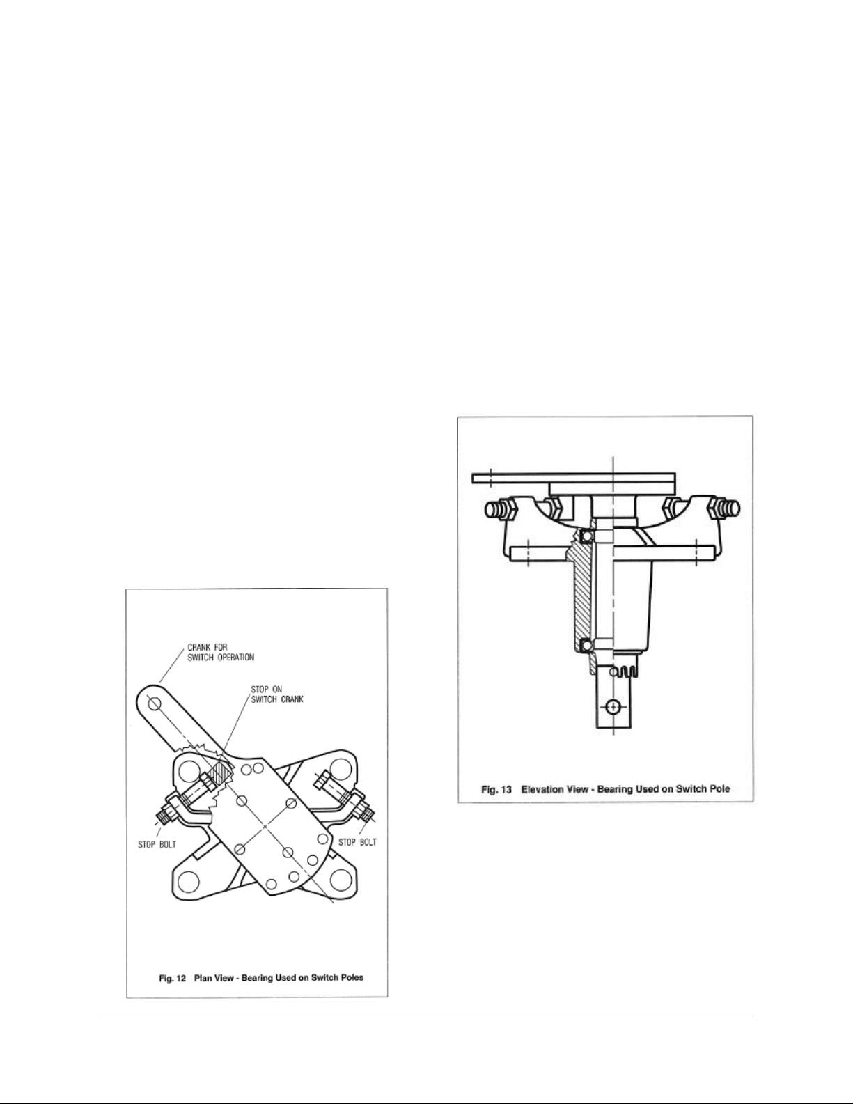
5. The single poles are held against or nearly
against their individual rotor bearing stops in
both the open and closed positions and also
the stops on the offset bearing.
6. Operating effort required to operate the
switch is not excessive.
Terminal Connections
The aluminum surface of the terminal
connection provides for easy current transfer.
Notice: In cases where a copper conductor is
used, bolt a tinned terminal clamp (if available)
to the aluminum switch terminal pad.
If a non-tinned terminal clamp is used, apply a
liberal amount of electrical joint grease at the
joint and all over the pad of the fitting.
To connect aluminum – to - aluminum
terminals:
1. Clean all contact surfaces of conductors and
fittings using a stiff wire brush to remove
heavy oxide coatings until the aluminum
finish is visible and restored.
2. Coat these now clean contact areas with a
liberal amount of corrosion inhibitor such as
NO-OX-ID”A Special” or No. 2 EJC.
3. Abrade the contact surface through the
corrosion inhibitor again using the stiff wire
brush.
Notice: Do not remove the compound.
4. Connect the terminals and tighten bolts
To connect copper-to-aluminum terminals:
1. Except for plated surfaces, clean all contact
surfaces of conductors and fittings using a
stiff wire brush to remove heavy oxide
coatings until the aluminum finish is visible
and restored.
2. Prepare any bare copper surfaces in the
usual manner.
3. Coat these now clean contact areas with a
liberal amount of corrosion inhibitor such as
NO-OX-ID “A Special” or no. 2 EJC.
4. Abrade the contact surface through the
corrosion inhibitor using a stiff wire brush.
Notice: Do not remove the electrical joint
grease.
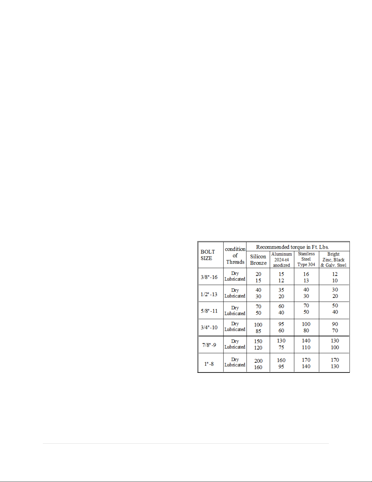
5. Connect the terminals and torque the bolts
as per Table 1.
MAINTENANCE
WARNING
Before servicing the switch, be sure it is
disconnected from all electric power
sources and properly grounded.

9 | Page
A certain amount of care and inspection is
recommended. The frequency of inspection
depends upon atmospheric conditions and
frequency of operation. The service interval is
largely determined by the user. Recommended
maintenance is similar to that listed in the latest
industry standards.1First, it is important that the
insulators are always clean. It is also important
that the contacts be examined to see that they are
aligned, clean, and have a firm uniform pressure.
If the contacts are pitted, or burned to some
extent, they should be removed and replaced.
Under normal service conditions, the jaw
contacts should be examined and maintained at
least once a year, depending upon the type of
atmosphere to which they are exposed.
Periodic maintenance should consist of cleaning
the contact surfaces thoroughly by carefully
scraping off any contamination or deposit and
sanding the surface entirely clean, a coating of
lubricant should be applied. Suggested
lubricants are MOBIL 28 grease or NO-OX-ID
“A Special”. MOBIL 28 is an Exxon Mobil
Company product. NO-OX-ID is made by
SANDCHEM INC.
1ANSI C37.35 (American National Standard Guide
for the Application, Installation, Operation and
Maintenance of High-Voltage Air Disconnecting and
Interrupter Switches)
In general, operating linkages require virtually
no maintenance. However, in contaminated
atmospheres of where operation under sleet
conditions is common some lubrication at pivot
points may be desirable. The grease used should
be durable even when exposed to the elements,
and should retain its viscosity over a wide
temperature range.
BEARINGS
The bearing of each switch and offset bearing is
a grease-less type. Figs. 12 and 13 show the
location of stop bolts and switch cranks on all
switch bearings. Figs. 14 and 15 show the
required location of stop blots and stop cranks
with a typical location of the adjustable radius
crank on the offset bearing.
Field Lubrication of Outdoor Switches
*None required at installation unless switches
were exposed to abnormal conditions during
storage for a considerable length of time.
During regular cleaning, give them a light coat
of grease.

10 | Page
RENEWAL PARTS
Refer to the switch nameplate when ordering
renewal parts. The nameplate is attached to
the base assembly of each switch pole. The
same data is shown on the record
engineering drawings. The master file at the
factory is linked to the serial number on the
nameplate.
Renewal Parts Ordering Information
Serial Number
Switch Type
Part Name
Quantity Required
Max. kV
B.I.L. kV
Cont. Amps
Mom. Amps
Refer your requests for renewal parts to the
Factory.
Table 2
Lubrication Guide for Outdoor Switch Components
Part Name Type Lubricants
Recommended
Amount
Applied
Qty. Req’d. for
(6) Three-pole
Switches
Jaw Fingers
NO-OX-ID Grade “A”
Special or Mobil 28
Grease
Medium
Coat
Blade Ends
NO-OX-ID Grade “A”
Special or Mobil 28
Grease
Medium
Coat (1) Quart
Pins On current
carrying parts
Mobil 28 Grease or DC-4 *
Pins On control
parts
Mobil 28 Grease or DC-4 Light Coat (1) Quart
Bearing Areas
On control parts
Mobil 28 Grease or DC-4
Medium
Coat
Terminal
Connections
NO-OX-ID Grade “A”
Special or NO 2 EJC
Heavy
Coat
(1) Quart
Table of contents
Other PASCOR ATLANTIC Industrial Equipment manuals
Popular Industrial Equipment manuals by other brands

Siemens
Siemens SINUMERIK ONE NCU 1760 Equipment manual

MiTEC
MiTEC WTX-14014539-70-ES Series Operation and maintenance manual

Tekelec
Tekelec EAGLE 5 Commands Error Recovery Manual

Siemens
Siemens Sivacon S8 operating instructions

Graphic Whizard
Graphic Whizard PT Air Jogger Operator's manual

KLR
KLR 5050-16 manual