manuals.online logo
Brands
  1. Home
  2. •
  3. Brands
  4. •
  5. PASCOR ATLANTIC
  6. •
  7. Industrial Equipment
  8. •
  9. PASCOR ATLANTIC TTT7 User manual

PASCOR ATLANTIC TTT7 User manual

IB-TTT7
May 2012
1 | Page
Contents
Subject Page
Receiving and Handling . . . . . . . . . . . . . . . . . . . . . . . . . . . . . . . . . . . . . . . . . . . . . . . . 2
Installation and Adjustment
Step 1. Check Bases . . . . . . . . . . . . . . . . . . . . . . . . . . . . . . . . . . . . . . . . 2
Step 2. Mounting Switch Bases . . . . . . . . . . . . . . . . . . . . . . . . . . . . . . . 2
Step 3. Mounting Operating Bearing . . . . . . . . . . . . . . . . . . . . . . . . . . . 3
Step 4. Mounting Insulators . . . . . . . . . . . . . . . . . . . . . . . . . . . . . . . . . 3
Step 5. Mounting Current Carrying Parts . . . . . . . . . . . . . . . . . . . . . . . 3
Step 6. Switch Adjustment . . . . . . . . . . . . . . . . . . . . . . . . . . . . . . . . . . 3
Step 7. Installing Interphase and Operating Connecting Rods . . . . . . . 4
Step 8. Installing Vertical Operating Pipe . . . . . . . . . . . . . . . . . . . . . 4
Step 9. Installing Vertical Operating Pipe and Operation Mechanism . . 5
Step 10. Arcing Horns or Arc Restrictors . . . . . . . . . . . . . . . . . . . . . . . . 7
Step 11. Installation of Sleet/Corona Shields . . . . . . . . . . . . . . . . . . . . . . 7
Step 12 Final Checks . . . . . . . . . . . . . . . . . . . . . . . . .. . . . . . . . . . . . . . . 7
Maintenance . . . . . . . . . . . . . . . . . . . . . . . . . . . . . . . . . . . . . . . . . . . . . . . . . . . . . . . . . . . 7
Terminal Connections . . . . . . . . . . . . . . . . . . . . . . . . . . . . . . . . . . . . . . . . . . . . . . . . . . . . 7
Renewal Parts . . . . . . . . . . . . . . . . . . . . . . . . . . . . . . . . . . . . . . . . . . . . . . . . . . . . . . . . . . . 9
Suggested Tools
•15/16” Open-End Wrench
•15/16” Socket
•3/4” Open-End Wrench (2)
•3/4” Socket
•1 1/2” Open-End Wrench or Adjustable
•Lineman Pliers
•Tape Measure
•Angle Finder
•Metal Cutting Saw
•Level
2 | Page
Leveling Screws
Shims Used for Leveling Switches
Shims (As Reqired)
Base Channel Flange
Rotor or Spacer Base
Leveling Screw
Rotor or Spacer Base
Base Channel Flange
Fig. 1 Types of Leveling Devices
Leveling Bolts
Rotor or Spacer Base
Base Channel Flange
Adjusting Nuts
Taper Washer
(When Used)
Taper Washer
(When Used)
Taper Washer
(When Used)
IMPORTANT: Read manual before installing or maintaining equipment! Make absolutely sure that
equipment is de-energized and properly grounded.
This manual should be used in conjunction with the factory drawings. The drawings contain critical
information, which if not followed could affect the operation of the switch.
Instructions can not cover all possible variations in equipment nor provide for every possible contingency
to be met in connection with installation, operation or maintenance. Should further information be
required or should particular problems arise which are not covered sufficiently for the purchaser’s
purposes, the concern should be referred to the factory.
For Technical Assistance Call 276-688-3328
RECEIVING INSPECTION
Check the shipment for completeness against the
bill of material and installation drawings. If
damage is found, file a claim immediately with the
transportation company and notify your Pascor
Atlantic representative.
HANDLING
Handling of disconnect switches should be done
with care. Porcelain is fragile and may be
damaged due to improper handling.
Factory drawings should be followed during
installation. It is recommended that switches be
fully assembled and adjusted at ground level
before being placed into position. This should
minimize final adjustments.
Lifting of switches by insulators, contacts, or live
parts should be avoided, because of possible
damage to these parts. Attachments for hoisting
should be made to the switch bases unless
otherwise instructed.
INSTALLATION AND ADJUSTMENT
If the switches have already been assembled with
insulators at the factory, proceed to step 5.
However, it is recommended that each switch pole
be checked for alignment and proper adjustment
after being mounted on the structure.
Step 1—Check Bases
Check bases to make sure that the spacers and
rotor bearing tops are square and level. If
necessary, make adjustments or shim. Shims are
normally used through 230kV and leveling screws
for 345 kV and above, see Fig. 1.
Step 2 —Mounting Switch Bases
Mount the switch bases on the supporting structure.
They should be level and parallel to each other, in
the position shown on the control drawing. One
switch base usually has additional cranks for
attaching either the main switch or the ground
switch to the operating bearing at the top of the
vertical-operating pipe. Make sure that this base is
placed in a position as called for on the control
drawing.
3 | Page
Step 3 —Mounting Operating Bearing
Mount the operating bearing and its supporting
base on the supporting structure as shown on the
control drawing. Check the operating crank for the
proper radius and angle. Also, make sure the stop
crank is mounted correctly and that the stops are
positioned correctly.
If the operating bearing has an adjustable crank, it
is sometimes necessary to add 1/4" to 1/2” to the
trial radius given on the control drawing to get
required travel to switch blades. This additional
length allows for lost motion and clearances in pin
holes and will also provide a definite audible
sound accompanied by a reasonable amount of
deflection in the structural members when the
crank crosses the dead canter position. This serves
as a signal to the operator that the switch is either
fully open or closed.
Step 4 -–Mounting Insulators
Using the bolts provided, assemble the insulators
to their supports on switch bases. Make sure that
operating cranks under the rotating column are
positioned properly (refer to the control and
single-pole switch drawings). If necessary to
adjust the insulator columns for variation in
heights or proper angle, use the shims, leveling
bolts or leveling screws as provided, see Fig. 1.
Step 5 — Mounting Current Carrying Parts
Rotate the center insulator column to the open
position as shown on the drawings. The stop at the
bottom of the column limits the travel. At this time,
the crank at the bottom of the insulator column will
be at an angle of 60° to the switch base. (On 345
and 500 kV switches, first mount corona rings on
top of insulators and under the current carrying
parts).
Mount the blade assembly on the center insulator
column at an angle of 70 degrees to the centerline
of the switch base which is 10 degrees further in a
clockwise direction than the switch crank, see Fig.
3. Mount the switch jaw assembly on the end
insulators leaving the mounting bolts finger tight in
order to allow for any adjustments later for proper
alignment.
Step 6 —Switch Adjustment (One Pole at a Time)
On an upright mounted switch, the direction of
rotation of the center insulator column (looking at
the switch form above) is clockwise to open and
counter clockwise to close.
6—1 Blade Entry
Using a piece of pipe over the crank at the bottom
of the rotating insulator stack, move the switch
blade slowly toward the closed position. The
4 | Page
contacts on the ends of the blade should approach
the jaw fingers at the same time and the blade
should hit both stops at about the same time. Also
the blade contacts, as they enter the jaw contacts,
should not rub the jaw fingers. If the blade rubs
the top fingers on one jaw and the bottom fingers
on the other, then a little adjustment at the bottom
of the center insulator stack with the shims of
leveling screws provided will usually result in
proper entry. If the blade rubs the top fingers on
both jaws or the bottom fingers on both jaws, then
a change in elevation is required and can be
achieved at the center stack of jaw stacks by using
the same shims of leveling screws. At this point,
recheck the blade penetration to see that the blade
hits both stops at the same time. If it doesn’t, the
shims and leveling screws will provide for
necessary adjustment.
When blade entry is satisfactorily achieved then
check to see if all jaw fingers are contacting the
blade end contact. If necessary, adjust with either
shim or leveling screws at the base of the jaw
insulator stacks. If it is expected that the
conductors to be attached to the terminal pads will
impose an appreciable force, it is recommended
that the jaw insulator columns be adjusted so that
the jaw fingers end up slightly off center on the
blade contact in a direction opposite to the
expected force. The jaw mounting bolts may now
be tightened.
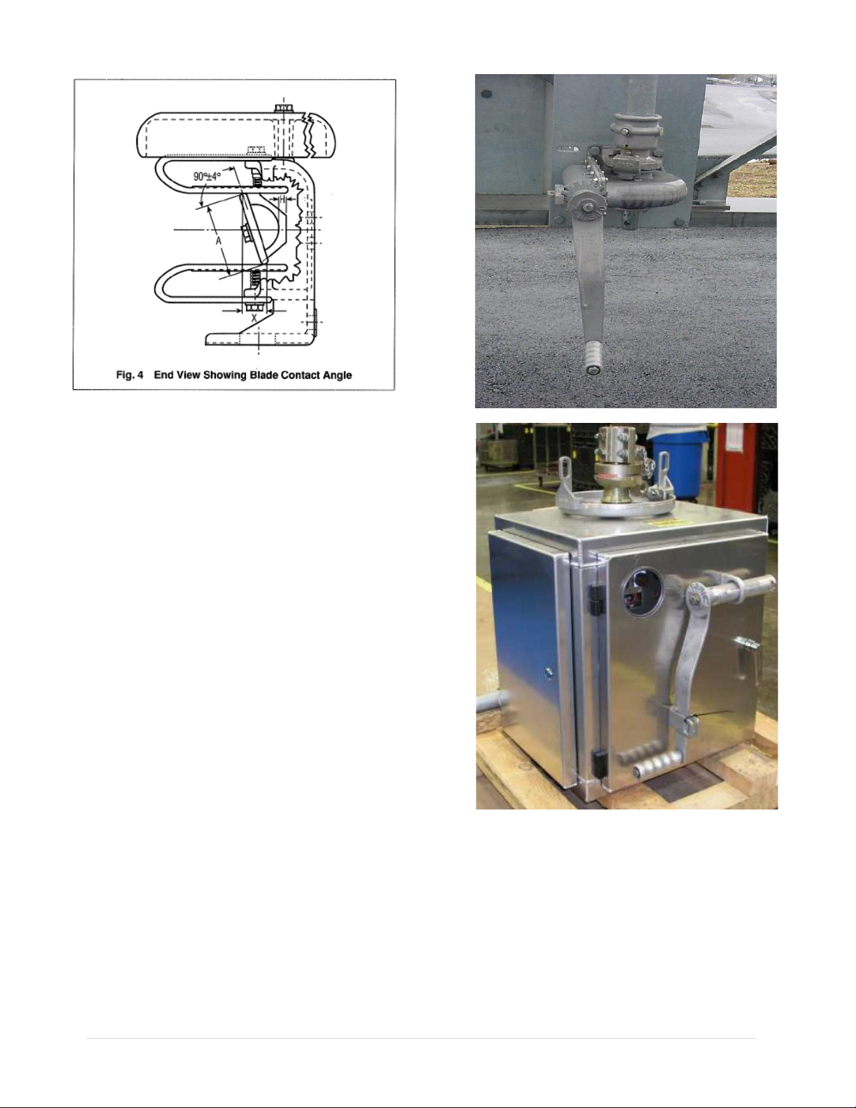
6—2 Blade Contact Angle
The blade contacts can be at a slight angle in the
closed position, (Fig. 4). An allowable contact
angle of 4 degrees permits an (dimension X) is
1/16” for each 1” of contact width. Example: If
contact width (A) is 4 1/2”, then dimension (X)
can be as much as 9/32” and still be within the
plus or minus 4 degree tolerance. Fig. 4 shows the
top of the blade contact leaning to the left. It is
also permissible for the top of the blade contact to
lean to the right as long as the 4 degree angle is
not exceeded. It is common to have both
situations on one three-pole switch. In fact, after
all three poles have been adjusted in the open
position, and then closed, you may find that one
pole will be high on the right, one fairly level and
one high on the left. This is due to many variables
and tolerances plus the free play or clearance in
pin connections of all the switches and control
parts.
6—3 Blade Engagement When Switch is Closed
Due to varying friction and deflection, the distance
between the blade and its stop (dimension H in Fig.
4), with the switch fully closed, may vary from 0”
to 1”. Insulator stacks can be adjusted to achieve
this. It is not usually possible to get this dimension
to be equal on all poles of a three-pole switch.
6—4 Stops on Current Carrying Parts
The stops on the blade mechanisms are set at the
factory and seldom require any adjustment.
However, if these stops prevent the blades from
turning to an acceptable closed of open position,
they should be re-adjusted.
After each pole has been adjusted, the open and
close stop bolts at the base of the rotating insulator
column should be set.
Step 7—Install Interphase and Offset Crank Rods
With all blades in the closed position, install the
interphase rods and offset crank rod as follows:
a. Lengthen the interphase rods that are in
compression during opening, as much as
possible, yet allowing for the pins to be
inserted.
b. On the rods that are in tension during opening,
shorten them as much as possible, yet allowing
for the pins to be inserted.
c. The offset crank rod between the outboard
bearing and the driven switch should be
handled the same way
Step 8—Install Vertical Operating Pipe
Attach vertical operating pipe to rotor bearing shaft, of
to offset rotor bearing shaft, with coupling pins
supplied. At this point, check drawings for accessory
equipment (auxiliary switches, mechanical interlocks,
position indicators, ground straps, etc.) which mounts
on vertical operating pipe and install before continuing
installation. The vertical pipe is predrilled at one end
for a 5/8” diameter pin, two of which are shipped,
together with a coupling, in a bad, for connection to
the offset bearing shaft (or on the pole unit rotor
bearing in the case of direct connection switches)
5 | Page
Step 9—Installing Operating Mechanism
Either a swing handle or a worm gear
mechanism is (normally) supplied for manual
switch operation.
Swing Handle Operator
To install the swing handle operator:
With ground strap in place on vertical operating
pipe, slide handle and handle lock plate over the
end of the vertical operating pipe. Fasten the lock
plate at the proper location. Recommended height
for the lock plate is 3 ft. 6 in. above ground.
Note: The lower end of the vertical operating pipe
should extend through the lock plate at least 3
inches. It may extend as much as 3 feet or more,
just so it doesn’t touch the ground or column
footing.
The lock plate assembly (Fig. 8) consists of two
castings, mounted on the pipe guide plate, which
can be easily adjusted in an arc to provide the
required rotation. These act as locks for the
manual operating handle when it is dropped from
the operating position. The handle must be raised
to a horizontal position for operation. With the
switch in the fully closed position, set the handle
clamp so its set screws are 4 inches above the lock
plate and its vertical centerline is at or near as
possible to the closed position, see Fig. 8.
Temporarily fasten the handle to the pipe with the
set screws. Operate the switch and move the
adjustable lock castings until they exert pressure
against the handle in both the open and closed
positions of the switch. This provides a slight
torsional wind-up in the operating pipe. Tighten the
two piercing set screws on the handle clamp until
holes are punched into the pipe and continue until
the screws are firmly seated.
Fig. 6 MO-10 Motor Operator
Fig. 5 Worm Gear Operator
6 | Page
7 | Page
Worm Gear Mechanism
With ground strap in place on vertical operating
pipe, slide worm gear mechanism (Fig. 5) over the
vertical operating pipe and attach it to the
structure. Remove the small position indicators,
which are attached to the worm gear coupling with
Allen set screws. Tighten hex head set screws in
the coupling until the vertical operating pipe is
pierced. The three-pole switch should now be
operated manually to check for proper adjustment.
If all stops at switch elevation have been set,
including the offset bearing, then it is safe to
reinstall the position indicators on the worm gear
mechanism. These indicators should not quite
touch the raised boss on the worm gear housing in
either the open or closed position. There is a
possibility of damage to the indicators or the
coupling if this is not observed
Motor Operator
For remote operation, a motor operator is supplied
and it should be installed per the instructions
supplied with it.
Step 10—Arcing Horns or Arc Restrictors
When arcing horns of Arc Restrictors are supplied,
they should now be installed and adjusted in
accordance with the drawings. The stationary horn
is attached to the jaw and should be adjusted, or
even bent slightly, to give a light contact pressure
between the horn and the switch blade.
Step 11—Installation of Sleet/Corona Shields
The combination sleet/corona shields should now
be installed over the blade mechanism at the top of
the center insulator stack and on top of the two
jaws as shown on single pole drawings.
Step12—Final Checks
The completed 3-pole installation should be
checked for the following:
1. In the open position, the blades should be at an
angle of 70° to the centerline of the switch
base, and stop at each base and the stop for the
operating bearing should be touching, or
nearly so. The indicator at the worm gear
operating mechanism should indicate the
switch is open.
2. In closing, blades should make central entry
into their jaws at approximately the same time.
3. In the closed position, all blades must be in
full contact with jaw contacts and also vertical
within the tolerances described previously. The
stop at each switch base and the stop for the
operating bearing should be touching, or nearly
so. The indicator to the worm gear operating
mechanism should indicate the switch is closed.
MAINTENANCE
A certain amount of care and inspection is
recommended. The frequency of inspection depends
upon atmospheric conditions and frequency of
operation. The service interval is largely
determined by the user. Recommended
maintenance is similar to that listed in the latest
industry standards.1First, it is important that the
insulators are always clean. It is also important that
the contacts be examined to see that they are
aligned, clean, and have a firm uniform pressure. If
the contacts are pitted, or burned to some extent,
they should be removed and replaced.
Under normal service conditions, the jaw contacts
should be examined and maintained at least once a
year, depending upon the type of atmosphere to
which they are exposed.
Periodic maintenance should consist of cleaning the
contact surfaces thoroughly by carefully scraping
off any contamination or deposit and sanding the
surface entirely clean, a coating of lubricant should
be applied. Suggested lubricants are MOBIL 28
grease of NO-OX-ID “A Special”. MOBIL 28 is an
Exxon Mobil Company product. NO-OX-ID is
made by SANDCHEM INC.
In general, operating linkages require virtually no
maintenance. However, in contaminated
atmospheres of where operation under sleet
conditions is common some lubrication at pivot
points may be desirable. The grease used should be
durable even when exposed to the elements, and
should retain its viscosity over a wide temperature
range.
Terminal Connections
The aluminum surface of the terminal connection
provides for easy current transfer.
1ANSI C37.35 (American National Standard Guide for
the Application, Installation, Operation and Maintenance
of High-Voltage Air Disconnecting and Interrupter
Switches)
8 | Page
Notice: In cases where a copper conductor is
used, bolt a tinned terminal clamp (if available) to
the aluminum switch terminal pad. If a non-tinned
terminal clamp is used, apply a liberal amount of
electrical joint grease at the joint and all over the
pad of the fitting.
To connect aluminum-to-aluminum terminals:
1. Clean all contact surfaces of conductors and
fittings using a stiff wire brush to remove
heavy oxide coatings until the aluminum
finish is visible and restored.
2. Coat these now clean contact areas with a
liberal amount of corrosion inhibitor such as
NO-OX-ID”A Special” or No. 2 EJC.
3. Abrade the contact surface through the
corrosion inhibitor again using the stiff wire
brush.
Notice: Do not remove the compound.
4. Connect the terminals and torque the bolts as
per Table 1.
To connect copper-to-aluminum terminals:
1. Except for plated surfaces, clean all contact
surfaces of conductors and fittings using a stiff
wire brush to remove heavy oxide coatings
until the aluminum finish is visible and
restored.
2. Prepare any bare copper surfaces in the usual
manner.
3. Coat these now clean contact areas with a
liberal amount of corrosion inhibitor such as
NO-OX-ID “A Special” or no. 2 EJC.
4. Abrade the contact surface through the
corrosion inhibitor using a stiff wire brush.
Notice: Do not remove the electrical joint grease.
5. Connect the terminals and torque the bolts as
per Table 1.
Table 1
Lubrication Guide for Outdoor Switch Components
Part Name Type Lubricants
Recommended
Amount
Applied
Qty. Req’d. for
(6) Three-pole
Switches
Jaw Fingers
NO-OX-ID Grade “A”
Special or Mobil 28
Grease
Medium
Coat
Blade Ends
NO-OX-ID Grade “A”
Special or Mobil 28
Grease
Medium
Coat (1) Quart
Pins On current
carrying parts
Mobil 28 Grease or DC-4 *
Pins On control
parts
Mobil 28 Grease or DC-4 Light Coat (1) Quart
Bearing Areas
On control parts
Mobil 28 Grease or DC-4
Medium
Coat
Terminal
Connections
NO-OX-ID Grade “A”
Special or NO 2 EJC
Heavy
Coat
(1) Quart
Page 9
RENEWAL PARTS
Refer to the switch nameplate when ordering
renewal parts. The nameplate is attached to
the base assembly of each switch pole. The
same data is shown on the record
engineering drawings. The master file at the
factory is linked to the serial number on the
nameplate.
Renewal Parts Ordering Information
Serial Number
Switch Type
Part Name
Quantity Required
Max. kV
B.I.L. kV
Cont. Amps
Mom. Amps
Refer your requests for renewal parts to the
Factory.

Other PASCOR ATLANTIC Industrial Equipment manuals

PASCOR ATLANTIC FAS2-V User manual

PASCOR ATLANTIC

PASCOR ATLANTIC FAS2-V User manual

PASCOR ATLANTIC MO-10 Instruction Manual

PASCOR ATLANTIC

PASCOR ATLANTIC MO-10 Instruction Manual

PASCOR ATLANTIC DR7 User manual

PASCOR ATLANTIC

PASCOR ATLANTIC DR7 User manual

Popular Industrial Equipment manuals by other brands

steute Ex AZM 415 Mounting and wiring instructions

steute

steute Ex AZM 415 Mounting and wiring instructions

Festo CTEU-VN operating instructions

Festo

Festo CTEU-VN operating instructions

enz 10.028 operating manual

enz

enz 10.028 operating manual

Trooper ADVANTAGE TR-100 instruction manual

Trooper

Trooper ADVANTAGE TR-100 instruction manual

Heinzmann StG 40.90-09 PD instruction manual

Heinzmann

Heinzmann StG 40.90-09 PD instruction manual

nord Power Genius 3000 installation guide

nord

nord Power Genius 3000 installation guide

Kässbohrer CONTAINER CHASSIS Series user manual

Kässbohrer

Kässbohrer CONTAINER CHASSIS Series user manual

DX Engineering DXE-RBS-1P manual

DX Engineering

DX Engineering DXE-RBS-1P manual

Uvitron Intelliray 600 instruction manual

Uvitron

Uvitron Intelliray 600 instruction manual

Rayzist 2034vx manual

Rayzist

Rayzist 2034vx manual

Siemens 3TK2810-1 manual

Siemens

Siemens 3TK2810-1 manual

Graco InvisiPac GS35 Plug-Free Instructions-parts list

Graco

Graco InvisiPac GS35 Plug-Free Instructions-parts list

Neis NECA 169 Installing and maintaining

Neis

Neis NECA 169 Installing and maintaining

Techniks 00450 Operation manual

Techniks

Techniks 00450 Operation manual

Vega VEGABAR 12 operating instructions

Vega

Vega VEGABAR 12 operating instructions

Siemens 3RK3111 operating instructions

Siemens

Siemens 3RK3111 operating instructions

Graco XM 255684 instructions

Graco

Graco XM 255684 instructions

SCHUNK ROTA-M flex 2+2 Series Assembly and operating manual

SCHUNK

SCHUNK ROTA-M flex 2+2 Series Assembly and operating manual

manuals.online logo
manuals.online logoBrands
  • About & Mission
  • Contact us
  • Privacy Policy
  • Terms and Conditions

Copyright 2025 Manuals.Online. All Rights Reserved.