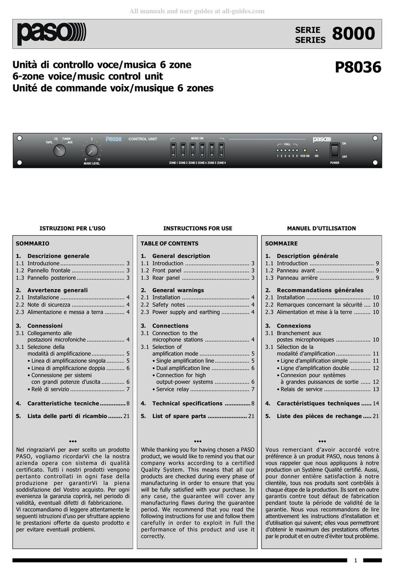
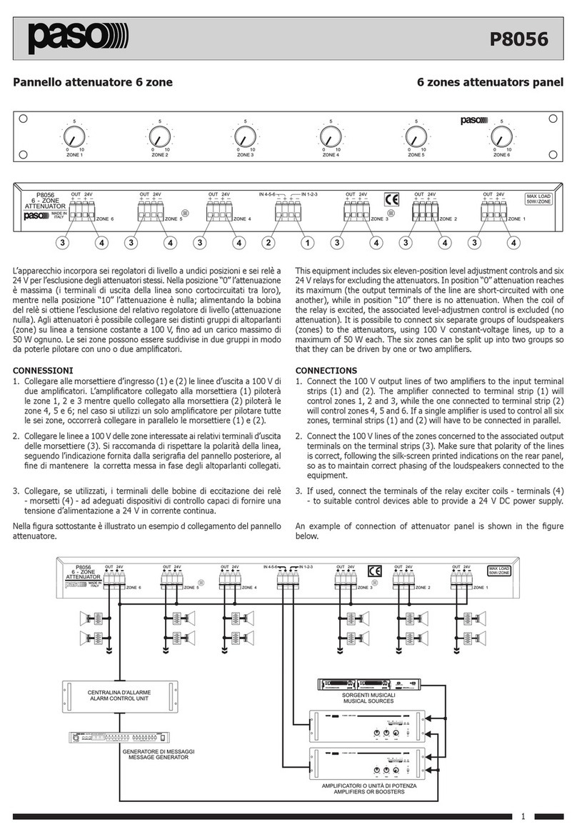
Paso PM2044-B User manual

1-PMS2000 System -
INTRODUZIONE
Nel ringraziarVi per aver scelto un prodotto
PASO, vogliamo ricordarVi che la nostra azienda
opera con sistema di qualità certificato.
Tutti i nostri prodotti vengono pertanto
controllati in ogni fase della produzione per
garantirVi la piena soddisfazione del Vostro
acquisto. Per ogni evenienza la garanzia coprirà,
nell’anno di validità, eventuali difetti di
fabbricazione. Vi raccomandiamo di leggere
attentamente le seguenti istruzioni d’uso per
sfruttare appieno le prestazioni offerte da
questo prodotto e per evitare eventuali
problemi.
INTRODUCTION
While thanking you for having chosen a PASO
product, we would like to remind you that our
company works according to a certified Quality
System. This means that all our products are
checked during every phase of manufacturing
in order to guarantee that you will be fully
satisfied with your purchase. At all events, the
guarantee will cover any manufacturing flaws
for the whole year for which it is valid. We
recommend that you read the following
instructions for use carefully in order to exploit
in full the performance of this product and to
avoid any problems.
NOTA
Nel continuo intento di migliorare i propri prodotti,
la PASO S.p.A. si riserva il diritto di apportare
modifiche ai disegni e alle caratteristiche tecniche
in qualsiasi momento e senza alcun preavviso.
NOTE
PASO S.p.A. strive to improve their products
continuously, and therefore reserve the right to
make changes to the drawings and technical
specifications at any time and without notice.
SISTEMA MODULARE PROFESSIONALE PMS2000
PMS2000 PROFESSIONAL MODULAR SYSTEM
Istruzioni per l’uso
Instructions for use
Manuel d'utilisation
Gebrauchsanleitung
Gebruiksaanwijzing
Instrucciones de empleo
Modulo selezione zone digitale
Digital-zones Selection module PM2044-B
Module numérique de sélection de zones
Digitales Zonenwahlmodul
Módulo numérico selección zonas
Digitale zoneselectiemodule
SWITCH
-PMS2000 System -
Ref. 11/547 PM2044-B
48
Via Mecenate, 90 - 20138 MILANO - ITALIA
TEL. +39-02-580 77 1 (15 linee r.a.)
FAX +39-02-580 77 277
http://www.paso.it
Printed in Italy - 09/06 - 0.05K - 11/547
S.p.A
NOTA
La PASO declina ogni responsabilità per danni a cose e/o persone derivanti dall'uso non corretto
dell'apparecchio o da procedure non rispondenti a quanto riportato sul presente libretto.
NOTE
PASO will not accept any liability for damage to property and/or persons arising out of incorrect
use of the equipment or of procedures that do not comply with the instructions provided in this
booklet. NOTE
PASO décline toute responsabilité en cas de dommages matériels et/ou physiques provoqués
par l'utilisation impropre de l'appareil ou encore par des opérations ou des interventions ne
respectant pas les instructions figurant dans la présente notice.
MERKE
PASO lehnt jede Haftung für Schäden an Personen und / oder Gegenständen ab, die durch
unzweckmäßige Verwendung oder Vorgehen entstehen, die nicht den Anweisungen dieses
Handbuches entsprechen. OPMERKING
PASO kan niet aansprakelijk worden gesteld voor schade aan voorwerpen en/of persoonlijk
letsel die het gevolg zijn van een onjuist gebruik van het apparaat of van procedures die niet
overeenkomen met de voorschriften uit deze handleiding.
NOTA
La PASO rehusa cualquier responsabilidad ante daños a cosas y/o personas causados por una
utilización no correcta del aparato o por operaciones no conformes a cuanto indicado en este
folleto.

-PMS2000 System -
Ref. 11/547 PM2044-B
2
1. DESCRIZIONE GENERALE 1. GENERAL DESCRIPTION
1.1 Descrizione pannello posteriore
[1] Terminali per linea ‘Musica’.
[2] Terminali per linea ‘Annunci’.
[3] Terminali linea 1.
[4] Terminali linea 2.
[5] Terminali linea 3.
[6] Terminali linea 4.
[7] Terminali linea 5.
[8] Terminali linea 6.
[9] Ingresso/uscita digitale.
[10] Connessione per allarme.
[11] Interruttori ‘Isolamento musica’.
1.1 Rear panel description
[1] Terminals for ‘Music’ line.
[2] Terminals for ‘Announcements’ line.
[3] Line 1 terminals.
[4] Line 2 terminals.
[5] Line 3 terminals.
[6] Line 4 terminals.
[7] Line 5 terminals.
[8] Line 6 terminals.
[9] Digital input/output.
[10] Connection for alarm.
[11] ‘Music disconnection’ switches.
GENERALITÀ
Il modulo selezione zone permette di indirizzare
una o due linee di amplificazione (generalmente
intese come
linea musica
e
linea annunci
)supiù
zone di ascolto (fino a sei). Per la selezione delle
zone è necessario utilizzare le postazioni
microfoniche PMB131 ePMB136.
La selezione delle zone è effettuata per mezzo
di appositi relais a doppio scambio. Uno scambio
di questi relè è utilizzato per la funzione di
OVERRIDE (annullamento delle attenuazioni
locali degli altoparlanti).
2. GENERAL INFORMATION
The zone-selection module can be used to direct
one or two amplification lines (usually
understood to mean the
music line
and the
announcement line
) to several listening zones
(up to six). It is necessary to use the PMB131
and PMB136 microphone stations to select the
zones. The zones are selected by means of
special relays with double change-over contacts.
One change-over contact of these relays is used
for the OVERRIDE function (cancellation of the
local attenuators of the loudspeakers).
-PMS2000 System -
Ref. 11/547 PM2044-B
○○○○○○○○○○○○○○○○○○○○○○○○○○○○○○○○○○○○○○○○○○○○
○○○○○○○○○○○○○○○○○○○○○○○○○○○○○○○○○○○○○○○○○○○○
○○○○○○○○○○○○○○○○○○○○○○○○○○○○○○○○○○○○○○○○○○○○
○○○○○○○○○○○○○○○○○○○○○○○○○○○○○○○○○○○○○○○○○○○○
○○○○○○○○○○○○○○○○○○○○○○○○○○○○○○○○○○○○○○○○○○○○
○○○○○○○○○○○○○○○○○○○○○○○○○○○○○○○○○○○○○○○○○○○○
○○○○○○○○○○○○○○○○○○○○○○○○○○○○○○○○○○○○○○○○○○○○
○○○○○○○○○○○○○○○○○○○○○○○○○○○○○○○○○○○○○○○○○○○○
○○○○○○○○○○○○○○○○○○○○○○○○○○○○○○○○○○○○○○○○○○○○
○○○○○○○○○○○○○○○○○○○○○○○○○○○○○○○○○○○○○○○○○○○○
○○○○○○○○○○○○○○○○○○○○○○○○○○○○○○○○○○○○○○○○○○○○
○○○○○○○○○○○○○○○○○○○○○○○○○○○○○○○○○○○○○○○○○○○○
○○○○○○○○○○○○○○○○○○○○○○○○○○○○○○○○○○○○○○○○○○○○
○○○○○○○○○○○○○○○○○○○○○○○○○○○○○○○○○○○○○○○○○○○○
○○○○○○○○○○○○○○○○○○○○○○○○○○○○○○○○○○○○○○○○○○○○
○○○○○○○○○○○○○○○○○○○○○○○○○○○○○○○○○○○○○○○○○○○○
○○○○○○○○○○○○○○○○○○○○○○○○○○○○○○○○○○○○○○○○○○○○
○○○○○○○○○○○○○○○○○○○○○○○○○○○○○○○○○○○○○○○○○○○○
○○○○○○○○○○○○○○○○○○○○○○○○○○○○○○○○○○○○○○○○○○○○
○○○○○○○○○○○○○○○○○○○○○○○○○○○○○○○○○○○○○○○○○○○○
○○○○○○○○○○○○○○○○○○○○○○○○○○○○○○○○○○○○○○○○○○○○
○○○○○○○○○○○○○○○○○○○○○○○○○○○○○○○○○○○○○○○○○○○○
○○○○○○○○○○○○○○○○○○○○○○○○○○○○○○○○○○○○○○○○○○○○
○○○○○○○○○○○○○○○○○○○○○○○○○○○○○○○○○○○○○○○○○○○○
○○○○○○○○○○○○○○○○○○○○○○○○○○○○○○○○○○○○○○○○○○○○
○○○○○○○○○○○○○○○○○○○○○○○○○○○○○○○○○○○○○○○○○○○○
○○○○○○○○○○○○○○○○○○○○○○○○○○○○○○○○○○○○○○○○○○○○
○○○○○○○○○○○○○○○○○○○○○○○○○○○○○○○○○○○○○○○○○○○○
○○○○○○○○○○○○○○○○○○○○○○○○○○○○○○○○○○○○○○○○○○○○
○○○○○○○○○○○○○○○○○○○○○○○○○○○○○○○○○○○○○○○○○○○○
○○○○○○○○○○○○○○○○○○○○○○○○○○○○○○○○○○○○○○○○○○○○
○○○○○○○○○○○○○○○○○○○○○○○○○○○○○○○○○○○○○○○○○○○○
○○○○○○○○○○○○○○○○○○○○○○○○○○○○○○○○○○○○○○○○○○○○
○○○○○○○○○○○○○○○○○○○○○○○○○○○○○○○○○○○○○○○○○○○○
○○○○○○○○○○○○○○○○○○○○○○○○○○○○○○○○○○○○○○○○○○○○
○○○○○○○○○○○○○○○○○○○○○○○○○○○○○○○○○○○○○○○○○○○○
○○○○○○○○○○○○○○○○○○○○○○○○○○○○○○○○○○○○○○○○○○○○
○○○○○○○○○○○○○○○○○○○○○○○○○○○○○○○○○○○○○○○○○○○○
○○○○○○○○○○○○○○○○○○○○○○○○○○○○○○○○○○○○○○○○○○○○
○○○○○○○○○○○○○○○○○○○○○○○○○○○○○○○○○○○○○○○○○○○○
○○○○○○○○○○○○○○○○○○○○○○○○○○○○○○○○○○○○○○○○○○○○
○○○○○○○○○○○○○○○○○○○○○○○○○○○○○○○○○○○○○○○○○○○○
○○○○○○○○○○○○○○○○○○○○○○○○○○○○○○○○○○○○○○○○○○○○
○○○○○○○○○○○○○○○○○○○○○○○○○○○○○○○○○○○○○○○○○○○○
○○○○○○○○○○○○○○○○○○○○○○○○○○○○○○○○○○○○○○○○○○○○
○○○○○○○○○○○○○○○○○○○○○○○○○○○○○○○○○○○○○○○○○○○○
○○○○○○○○○○○○○○○○○○○○○○○○○○○○○○○○○○○○○○○○○○○○
○○○○○○○○○○○○○○○○○○○○○○○○○○○○○○○○○○○○○○○○○○○○
47

-PMS2000 System -
Ref. 11/547 PM2044-B
3
3. INSTALLAZIONE
Anche se i moduli selezione zone possono essere
inseriti in una posizione qualsiasi all'interno
del cestello PMS2002-B, se ne raccomanda
l'installazione, dato l'assorbimento di corrente
più alto degli altri moduli del sistema, nelle
posizioni più prossime a quella del modulo
alimentatore. In un sistema nel quale devono
essere utilizzati più moduli selezione zone si
dovrà provvedere ad installare questi ultimi
cestello. Gli altri moduli del sistema andranno
installati, proseguendo verso sinistra, dopo quelli
di selezione zone (vedi figura 3.1).
3. INSTALLATION
Although the zone-selection modules can be
inserted in any position inside the PMS2002-B
card cage, their installation in the positions closest
to that of the power-supply module is
recommended due to the fact that they absorb
more current than the other modules making up
the system. In a system in which several zone-
selection modules are to be used, these will have
to be installed in the positions at the extreme
right-hand end of the card cage. The other
modules will then have to be installed after the
zone-selection modules, proceeding towards the
left (see Figure 3.1).
A = Moduli selezione zone
Zone-selection modules
Fig. 3.1
NOTA
Il modulo selezione zone non ha alcuna influenza
sulle linee di segnale e di controllo del cestello,
pertanto, la sua posizione non determina alcuna
variazione nella funzionalità dei vari busses.
Prima d'installare il modulo è necessario
provvedere alla configurazione di alcuni settaggi
presenti sulla scheda secondo quanto descritto
nei paragrafi seguenti.
Seguire, per l’installazione, le istruzioni di
montaggio allegate al cestello dei moduli
PMS2002-B.
IMPORTANTE
I terminali marcati con il simbolo
sono attivi e pericolosi.
Il cablaggio esterno collegato a questi terminali,
DEVE essere eseguito esclusivamente da
personale specializzato.
NOTE
The zone-selection module does not affect the
signal and control lines of the card-cage in any
way, and therefore its position does not cause
any changes in the functional characteristics of
the various busses. Before installing the module,
it is necessary to configure some settings on
the card, on the basis of the descriptions
contained in the following paragraphs. Carry out
the installation following the mounting
instructions supplied with the card cages of the
PMS2002-B modules.
IMPORTANT
The terminals marked with the symbol
are active and dangerous.
The external connections toward these
terminals MUST be carried out by specialized
personnel only.
-PMS2000 System -
Ref. 11/547 PM2044-B
46
○○○○○○○○○○○○○○○○○○○○○○○○○○○○○○○○○○○○○○○○○○○○
○○○○○○○○○○○○○○○○○○○○○○○○○○○○○○○○○○○○○○○○○○○○
○○○○○○○○○○○○○○○○○○○○○○○○○○○○○○○○○○○○○○○○○○○○
○○○○○○○○○○○○○○○○○○○○○○○○○○○○○○○○○○○○○○○○○○○○
○○○○○○○○○○○○○○○○○○○○○○○○○○○○○○○○○○○○○○○○○○○○
○○○○○○○○○○○○○○○○○○○○○○○○○○○○○○○○○○○○○○○○○○○○
○○○○○○○○○○○○○○○○○○○○○○○○○○○○○○○○○○○○○○○○○○○○
○○○○○○○○○○○○○○○○○○○○○○○○○○○○○○○○○○○○○○○○○○○○
○○○○○○○○○○○○○○○○○○○○○○○○○○○○○○○○○○○○○○○○○○○○
○○○○○○○○○○○○○○○○○○○○○○○○○○○○○○○○○○○○○○○○○○○○
○○○○○○○○○○○○○○○○○○○○○○○○○○○○○○○○○○○○○○○○○○○○
○○○○○○○○○○○○○○○○○○○○○○○○○○○○○○○○○○○○○○○○○○○○
○○○○○○○○○○○○○○○○○○○○○○○○○○○○○○○○○○○○○○○○○○○○
○○○○○○○○○○○○○○○○○○○○○○○○○○○○○○○○○○○○○○○○○○○○
○○○○○○○○○○○○○○○○○○○○○○○○○○○○○○○○○○○○○○○○○○○○
○○○○○○○○○○○○○○○○○○○○○○○○○○○○○○○○○○○○○○○○○○○○
○○○○○○○○○○○○○○○○○○○○○○○○○○○○○○○○○○○○○○○○○○○○
○○○○○○○○○○○○○○○○○○○○○○○○○○○○○○○○○○○○○○○○○○○○
○○○○○○○○○○○○○○○○○○○○○○○○○○○○○○○○○○○○○○○○○○○○
○○○○○○○○○○○○○○○○○○○○○○○○○○○○○○○○○○○○○○○○○○○○
○○○○○○○○○○○○○○○○○○○○○○○○○○○○○○○○○○○○○○○○○○○○
○○○○○○○○○○○○○○○○○○○○○○○○○○○○○○○○○○○○○○○○○○○○
○○○○○○○○○○○○○○○○○○○○○○○○○○○○○○○○○○○○○○○○○○○○
○○○○○○○○○○○○○○○○○○○○○○○○○○○○○○○○○○○○○○○○○○○○
○○○○○○○○○○○○○○○○○○○○○○○○○○○○○○○○○○○○○○○○○○○○
○○○○○○○○○○○○○○○○○○○○○○○○○○○○○○○○○○○○○○○○○○○○
○○○○○○○○○○○○○○○○○○○○○○○○○○○○○○○○○○○○○○○○○○○○
○○○○○○○○○○○○○○○○○○○○○○○○○○○○○○○○○○○○○○○○○○○○
○○○○○○○○○○○○○○○○○○○○○○○○○○○○○○○○○○○○○○○○○○○○
○○○○○○○○○○○○○○○○○○○○○○○○○○○○○○○○○○○○○○○○○○○○
○○○○○○○○○○○○○○○○○○○○○○○○○○○○○○○○○○○○○○○○○○○○
○○○○○○○○○○○○○○○○○○○○○○○○○○○○○○○○○○○○○○○○○○○○
○○○○○○○○○○○○○○○○○○○○○○○○○○○○○○○○○○○○○○○○○○○○
○○○○○○○○○○○○○○○○○○○○○○○○○○○○○○○○○○○○○○○○○○○○
○○○○○○○○○○○○○○○○○○○○○○○○○○○○○○○○○○○○○○○○○○○○
○○○○○○○○○○○○○○○○○○○○○○○○○○○○○○○○○○○○○○○○○○○○
○○○○○○○○○○○○○○○○○○○○○○○○○○○○○○○○○○○○○○○○○○○○
○○○○○○○○○○○○○○○○○○○○○○○○○○○○○○○○○○○○○○○○○○○○
○○○○○○○○○○○○○○○○○○○○○○○○○○○○○○○○○○○○○○○○○○○○
○○○○○○○○○○○○○○○○○○○○○○○○○○○○○○○○○○○○○○○○○○○○
○○○○○○○○○○○○○○○○○○○○○○○○○○○○○○○○○○○○○○○○○○○○
○○○○○○○○○○○○○○○○○○○○○○○○○○○○○○○○○○○○○○○○○○○○
○○○○○○○○○○○○○○○○○○○○○○○○○○○○○○○○○○○○○○○○○○○○
○○○○○○○○○○○○○○○○○○○○○○○○○○○○○○○○○○○○○○○○○○○○
○○○○○○○○○○○○○○○○○○○○○○○○○○○○○○○○○○○○○○○○○○○○
○○○○○○○○○○○○○○○○○○○○○○○○○○○○○○○○○○○○○○○○○○○○
○○○○○○○○○○○○○○○○○○○○○○○○○○○○○○○○○○○○○○○○○○○○
○○○○○○○○○○○○○○○○○○○○○○○○○○○○○○○○○○○○○○○○○○○○

-PMS2000 System -
Ref. 11/547 PM2044-B
4
3.1 Isolamento linea ‘MUSICA’
In condizione di riposo (nessuna zona
selezionata) la linea di ogni singola zona è
collegata alla linea di amplificazione ‘MUSICA’,
cioè, alla linea di amplificazione collegata ai
terminali ‘0V M’e‘LM’[1] (impostazione di
default). È possibile isolare ogni singola zona dalla
linea ‘Musica’ azionando il relativo interruttore sul
frontale.
3.1 Insulation of the ‘MUSIC’ line
In idle conditions (no zones selected), the line
of each single zone is connected to the ‘MUSIC’
amplification line, that is to say to the
amplification line connected to the ‘0V M’ and
‘LM’ terminals [1] (default setting).
It is possible to cut off each single zone from the
‘Music’ line by means of the appropriate switch
on the front panel.
Fig. 3.1.1
Isolando una zona dalla linea ‘Musica’
s'impedisce che, in condizione di riposo (zona
non selezionata), venga distribuito alcun
segnale.
Insulating a zone from the ‘Music’ line prevents
any signals from being distributed to it in the
idle condition (zone not selected).
3.2 Selezione del modo di funzionamento
3.2.1 Funzionamento con
linea di amplificazione singola
Il modulo è pre-impostato per l'impiego in sistemi
dotati di una singola linea di amplificazione per
entrambi i programmi sonori: musica di
sottofondo e annunci (vedi par. 4.1).
Con questa impostazione la selezione di una o
più zone determina il silenziamento delle zone
non selezionate.
3.2 Selection of the operating mode
3.2.1 Operation with
a single amplification line
The module is pre-set for use in systems that
have a single amplification line for both sound
programmes, i.e. background music and
announcements (see point 4.1).
With this setting, selecting one or more zones
causes muting of those zones that have not been
selected.
-PMS2000 System -
Ref. 11/547 PM2044-B
-PMS2000 System -
Ref. 11/547 PM2044-B
45
○○○○○○○○○○○○○○○○○○○○○○○○○○○○○○○○○○○○○○○○○○○○
○○○○○○○○○○○○○○○○○○○○○○○○○○○○○○○○○○○○○○○○○○○○
○○○○○○○○○○○○○○○○○○○○○○○○○○○○○○○○○○○○○○○○○○○○
○○○○○○○○○○○○○○○○○○○○○○○○○○○○○○○○○○○○○○○○○○○○
○○○○○○○○○○○○○○○○○○○○○○○○○○○○○○○○○○○○○○○○○○○○
○○○○○○○○○○○○○○○○○○○○○○○○○○○○○○○○○○○○○○○○○○○○
○○○○○○○○○○○○○○○○○○○○○○○○○○○○○○○○○○○○○○○○○○○○
○○○○○○○○○○○○○○○○○○○○○○○○○○○○○○○○○○○○○○○○○○○○
○○○○○○○○○○○○○○○○○○○○○○○○○○○○○○○○○○○○○○○○○○○○
○○○○○○○○○○○○○○○○○○○○○○○○○○○○○○○○○○○○○○○○○○○○
○○○○○○○○○○○○○○○○○○○○○○○○○○○○○○○○○○○○○○○○○○○○
○○○○○○○○○○○○○○○○○○○○○○○○○○○○○○○○○○○○○○○○○○○○
○○○○○○○○○○○○○○○○○○○○○○○○○○○○○○○○○○○○○○○○○○○○
○○○○○○○○○○○○○○○○○○○○○○○○○○○○○○○○○○○○○○○○○○○○
○○○○○○○○○○○○○○○○○○○○○○○○○○○○○○○○○○○○○○○○○○○○
○○○○○○○○○○○○○○○○○○○○○○○○○○○○○○○○○○○○○○○○○○○○
○○○○○○○○○○○○○○○○○○○○○○○○○○○○○○○○○○○○○○○○○○○○
○○○○○○○○○○○○○○○○○○○○○○○○○○○○○○○○○○○○○○○○○○○○
○○○○○○○○○○○○○○○○○○○○○○○○○○○○○○○○○○○○○○○○○○○○
○○○○○○○○○○○○○○○○○○○○○○○○○○○○○○○○○○○○○○○○○○○○
○○○○○○○○○○○○○○○○○○○○○○○○○○○○○○○○○○○○○○○○○○○○
○○○○○○○○○○○○○○○○○○○○○○○○○○○○○○○○○○○○○○○○○○○○
○○○○○○○○○○○○○○○○○○○○○○○○○○○○○○○○○○○○○○○○○○○○
○○○○○○○○○○○○○○○○○○○○○○○○○○○○○○○○○○○○○○○○○○○○
○○○○○○○○○○○○○○○○○○○○○○○○○○○○○○○○○○○○○○○○○○○○
○○○○○○○○○○○○○○○○○○○○○○○○○○○○○○○○○○○○○○○○○○○○
○○○○○○○○○○○○○○○○○○○○○○○○○○○○○○○○○○○○○○○○○○○○
○○○○○○○○○○○○○○○○○○○○○○○○○○○○○○○○○○○○○○○○○○○○
○○○○○○○○○○○○○○○○○○○○○○○○○○○○○○○○○○○○○○○○○○○○
○○○○○○○○○○○○○○○○○○○○○○○○○○○○○○○○○○○○○○○○○○○○
○○○○○○○○○○○○○○○○○○○○○○○○○○○○○○○○○○○○○○○○○○○○
○○○○○○○○○○○○○○○○○○○○○○○○○○○○○○○○○○○○○○○○○○○○
○○○○○○○○○○○○○○○○○○○○○○○○○○○○○○○○○○○○○○○○○○○○
○○○○○○○○○○○○○○○○○○○○○○○○○○○○○○○○○○○○○○○○○○○○
○○○○○○○○○○○○○○○○○○○○○○○○○○○○○○○○○○○○○○○○○○○○
○○○○○○○○○○○○○○○○○○○○○○○○○○○○○○○○○○○○○○○○○○○○
○○○○○○○○○○○○○○○○○○○○○○○○○○○○○○○○○○○○○○○○○○○○
○○○○○○○○○○○○○○○○○○○○○○○○○○○○○○○○○○○○○○○○○○○○
○○○○○○○○○○○○○○○○○○○○○○○○○○○○○○○○○○○○○○○○○○○○
○○○○○○○○○○○○○○○○○○○○○○○○○○○○○○○○○○○○○○○○○○○○
○○○○○○○○○○○○○○○○○○○○○○○○○○○○○○○○○○○○○○○○○○○○
○○○○○○○○○○○○○○○○○○○○○○○○○○○○○○○○○○○○○○○○○○○○
○○○○○○○○○○○○○○○○○○○○○○○○○○○○○○○○○○○○○○○○○○○○
○○○○○○○○○○○○○○○○○○○○○○○○○○○○○○○○○○○○○○○○○○○○
○○○○○○○○○○○○○○○○○○○○○○○○○○○○○○○○○○○○○○○○○○○○
○○○○○○○○○○○○○○○○○○○○○○○○○○○○○○○○○○○○○○○○○○○○
○○○○○○○○○○○○○○○○○○○○○○○○○○○○○○○○○○○○○○○○○○○○
○○○○○○○○○○○○○○○○○○○○○○○○○○○○○○○○○○○○○○○○○○○○

-PMS2000 System -
Ref. 11/547 PM2044-B
5
3.2.2 Funzionamento con
linea di amplificazione doppia
Il modulo può funzionare anche in impianti dotati
di due linee di amplificazione separate: una per
la diffusione di musica di sottofondo ed una per
la diffusione degli annunci (vedi par. 4.2).
Per impostare il modulo per il funzionamento
con la doppia linea di amplificazione è necessario
rimuovere il ponticello dai terminali del
connettore CN107 (particolare [D] di fig. 3.1.1).
3.2.2 Operation with
a double amplification line
The module can also operate in systems
equipped with two separate amplification lines:
one for broadcasting background music and one
for broadcasting the announcements (see point
4.2). To set the module for operation with the
double amplification line it is necessary to
remove the jumper from the terminals of
connector CN107 (detail [D] in Figure 3.1.1).
3.3. Alimentazione
Questo modulo viene alimentato dalla linea a
24V del cestello nel quale risulta installato.
Al morsetto ‘+24V’ è disponibile un'alimentazione
per attivare, tramite interruttore esterno,
l'allarme che inserisce tutte e sei le zone del
modulo.
3.3. Power supply
This module is powered from the 24 V line of
the card-cage in which it is installed. On the
‘+24V’ there is a power supply for activating
the alarm that includes all six zones covered
by the module. This power supply is activated
by means of an external switch.
-PMS2000 System -
Ref. 11/547 PM2044-B
44
○○○○○○○○○○○○○○○○○○○○○○○○○○○○○○○○○○○○○○○○○○○○
○○○○○○○○○○○○○○○○○○○○○○○○○○○○○○○○○○○○○○○○○○○○
○○○○○○○○○○○○○○○○○○○○○○○○○○○○○○○○○○○○○○○○○○○○
○○○○○○○○○○○○○○○○○○○○○○○○○○○○○○○○○○○○○○○○○○○○
○○○○○○○○○○○○○○○○○○○○○○○○○○○○○○○○○○○○○○○○○○○○
○○○○○○○○○○○○○○○○○○○○○○○○○○○○○○○○○○○○○○○○○○○○
○○○○○○○○○○○○○○○○○○○○○○○○○○○○○○○○○○○○○○○○○○○○
○○○○○○○○○○○○○○○○○○○○○○○○○○○○○○○○○○○○○○○○○○○○
○○○○○○○○○○○○○○○○○○○○○○○○○○○○○○○○○○○○○○○○○○○○
○○○○○○○○○○○○○○○○○○○○○○○○○○○○○○○○○○○○○○○○○○○○
○○○○○○○○○○○○○○○○○○○○○○○○○○○○○○○○○○○○○○○○○○○○
○○○○○○○○○○○○○○○○○○○○○○○○○○○○○○○○○○○○○○○○○○○○
○○○○○○○○○○○○○○○○○○○○○○○○○○○○○○○○○○○○○○○○○○○○
○○○○○○○○○○○○○○○○○○○○○○○○○○○○○○○○○○○○○○○○○○○○
○○○○○○○○○○○○○○○○○○○○○○○○○○○○○○○○○○○○○○○○○○○○
○○○○○○○○○○○○○○○○○○○○○○○○○○○○○○○○○○○○○○○○○○○○
○○○○○○○○○○○○○○○○○○○○○○○○○○○○○○○○○○○○○○○○○○○○
○○○○○○○○○○○○○○○○○○○○○○○○○○○○○○○○○○○○○○○○○○○○
○○○○○○○○○○○○○○○○○○○○○○○○○○○○○○○○○○○○○○○○○○○○
○○○○○○○○○○○○○○○○○○○○○○○○○○○○○○○○○○○○○○○○○○○○
○○○○○○○○○○○○○○○○○○○○○○○○○○○○○○○○○○○○○○○○○○○○
○○○○○○○○○○○○○○○○○○○○○○○○○○○○○○○○○○○○○○○○○○○○
○○○○○○○○○○○○○○○○○○○○○○○○○○○○○○○○○○○○○○○○○○○○
○○○○○○○○○○○○○○○○○○○○○○○○○○○○○○○○○○○○○○○○○○○○
○○○○○○○○○○○○○○○○○○○○○○○○○○○○○○○○○○○○○○○○○○○○
○○○○○○○○○○○○○○○○○○○○○○○○○○○○○○○○○○○○○○○○○○○○
○○○○○○○○○○○○○○○○○○○○○○○○○○○○○○○○○○○○○○○○○○○○
○○○○○○○○○○○○○○○○○○○○○○○○○○○○○○○○○○○○○○○○○○○○
○○○○○○○○○○○○○○○○○○○○○○○○○○○○○○○○○○○○○○○○○○○○
○○○○○○○○○○○○○○○○○○○○○○○○○○○○○○○○○○○○○○○○○○○○
○○○○○○○○○○○○○○○○○○○○○○○○○○○○○○○○○○○○○○○○○○○○
○○○○○○○○○○○○○○○○○○○○○○○○○○○○○○○○○○○○○○○○○○○○
○○○○○○○○○○○○○○○○○○○○○○○○○○○○○○○○○○○○○○○○○○○○
○○○○○○○○○○○○○○○○○○○○○○○○○○○○○○○○○○○○○○○○○○○○
○○○○○○○○○○○○○○○○○○○○○○○○○○○○○○○○○○○○○○○○○○○○
○○○○○○○○○○○○○○○○○○○○○○○○○○○○○○○○○○○○○○○○○○○○
○○○○○○○○○○○○○○○○○○○○○○○○○○○○○○○○○○○○○○○○○○○○
○○○○○○○○○○○○○○○○○○○○○○○○○○○○○○○○○○○○○○○○○○○○
○○○○○○○○○○○○○○○○○○○○○○○○○○○○○○○○○○○○○○○○○○○○
○○○○○○○○○○○○○○○○○○○○○○○○○○○○○○○○○○○○○○○○○○○○
○○○○○○○○○○○○○○○○○○○○○○○○○○○○○○○○○○○○○○○○○○○○
○○○○○○○○○○○○○○○○○○○○○○○○○○○○○○○○○○○○○○○○○○○○
○○○○○○○○○○○○○○○○○○○○○○○○○○○○○○○○○○○○○○○○○○○○
○○○○○○○○○○○○○○○○○○○○○○○○○○○○○○○○○○○○○○○○○○○○
○○○○○○○○○○○○○○○○○○○○○○○○○○○○○○○○○○○○○○○○○○○○
○○○○○○○○○○○○○○○○○○○○○○○○○○○○○○○○○○○○○○○○○○○○
○○○○○○○○○○○○○○○○○○○○○○○○○○○○○○○○○○○○○○○○○○○○
○○○○○○○○○○○○○○○○○○○○○○○○○○○○○○○○○○○○○○○○○○○○

-PMS2000 System -
Ref. 11/547 PM2044-B
6
4. CONNESSIONI ED USO
Il modulo dispone di morsettiere a vite di tipo
estraibile per le varie connessioni ai dispositivi
di comando dei relais, alle linee degli altoparlanti
e agli amplificatori.
Si raccomanda di utilizzare, per i collegamenti,
cavi di buona qualità e di prestare particolare
cura, durante la realizzazione degli stessi,
affinchè i conduttori non presentino sfilacciature
o contatti incerti.
I morsetti accettano cavi con sezione
massima di 2,5 mm2.
Ogni relè del modulo è in grado di sopportare
una potenza massima della linea di cinquecento
watt. Questi moduli possono essere pilotati
esclusivamente dalle postazioni microfoniche
digitali PASO PMB131 e/o PMB136, in grado
di gestire fino a trentasei zone. Quindi,
all'interno del Sistema Modulare PMS2000, è
possibile montare il numero massimo di sei
moduli zone.
4. CONNECTIONS AND USE
The module has terminal strips with binding
screws of the removable type for the various
connections to the relay control devices, to the
loudspeaker lines and to the amplifiers.
It is strongly recommended that the connections
be made using good-quality cables and that
particular care should be taken while making
the connections to avoid using frayed cables or
uncertain contacts.
The terminals will take cables with a maximum
cross-section of 2,5 mm2.
Each relay of the module is able to take a max.
potential of the line of five hundred watt.
These modules can only be driven by PASO
PMB131 and/or PMB136 digital microphone
stations, which are capable of managing up to
thirty-six zones. It is therefore possible to
mount a maximum of six zone modules inside
the PMS2000 Modular System.
Seguendo le indicazioni della tabella sottostante,
impostare l'indirizzo di riconoscimento per
ciascuno dei moduli tramite i ponticelli CN108,
CN109 eCN110 (vedi figura).
The jumpers CN108,CN109 and CN110
(see figure) can be used to set the address of
each module. For this purpose, follow the
indications shown in the below table.
Indirizzo CN110 CN109 CN108
1–––
2–•–
3•––
4••–
5––•
6–••
•= ponticello inserito
–= ponticello non inserito
Address CN110 CN109 CN108
1–––
2–•–
3•––
4••–
5––•
6–••
•= jumper inserted
–= jumper not inserted
-PMS2000 System -
Ref. 11/547 PM2044-B
43
Aan het einde van zijn levensduur mag het
product niet samen met het gewone
huishoudelijke afval worden verwerkt. Het
moet naar het daartoe bestemde gemeentelijke
verzamelpunt voor gescheiden afval worden
gebracht, of naar een verkooppunt dat deze
service verleent. Het apart verwerken van
afgedankte elektrische en elektronische
apparatuur (AEEA) voorkomt mogelijk
negatieve gevolgen voor het milieu en
de gezondheid die door een ongeschikte
verwerking ontstaan en zorgt ervoor dat
de materialen waaruit het apparaat is
samengesteld teruggewonnen kunnen
worden om een aanmerkelijke besparing
van energie en grondstoffen te
verkrijgen. Om op de verplichting tot gescheiden
verwerking van elektrische apparatuur te wijzen,
is op het product het symbool van een
doorgekruiste vuilnisbak aangebracht.
Am Ende seiner Nutzzeit darf das Produkt nicht
zusammen mit dem Siedlungsabfall beseitigt
werden, sondern es muss bei den zu diesem
Zweck von den städtischen Behörden
eingerichteten Sammelstellen oder zu den
Fachhändlern, die einen Rücknahmeservice
anbieten, gebracht werden. Die getrennte
Entsorgung von Elektro- und Elektronik-
Altgeräten (WEEE - Waste Electric and
Electronic Equipment) vermeidet mögliche
negative Auswirkungen auf die Umwelt
und die Gesundheit infolge einer nicht
vorschriftsmäßigen Entsorgung. Zudem
wird die Wiederverwertung der
Materialen, aus denen das Gerät besteht,
ermöglicht, so dass eine bedeutende
Einsparung an Energie und Ressourcen erzielt
wird. Aus diesem Grund ist das Produkt mit dem
Symbol einer durchgestrichenen Mülltonne
gekennzeichnet.
!
Correcte verwerking van het
product in overeenstemming met
de Europese Richtlijn 2002/96/EC
!
Wichtiger Hinweis für die Entsorgung
des Produkts in Ubereinstimmung
mit der EG-Richtlinie 2002/96/EC
Dit product is conform de Richtlijnen
van de Europese Gemeenschap
waaronder het valt.
Dieses Produkt entspricht den
diesbezüglichen EU-Richtlinien.
•GARANTIE •
Dit product is gegarandeerd vrij van materiaal-
en constructiefouten; de garantieduur wordt
geregeld door de geldende wettelijke
voorschriften. Paso voert de reparatie van de
hier gegarandeerde defecte producten kosteloos
uit, indien blijkt dat het defect tijdens normaal
gebruik is opgetreden. De garantie heeft dus
geen betrekking op verkeerd gebruikte of
geïnstalleerde producten, producten die
mechanisch beschadigd zijn of beschadigingen
hebben opgelopen door vloeistoffen of de invloed
van weersomstandigheden. Producten waarbij
een defect is geconstateerd dienen franco
verzend- en retourkosten aan Paso opgestuurd
te worden. Deze garantie omvat geen enkele
andere expliciete of impliciete garantie en dekt
geen schade aan personen of zaken.
Voor verdere informatie over de garantie dient
contact opgenomen te worden met de
dichtstbijzijnde PASO distributeur.
•GARANTIE •
Für dieses Produkt wird eine Garantie für
Rohmaterialfehler und Montagefehler gewährt;
die Garantiezeit unterliegt den gültigen
gesetzlichen Bestimmungen. Paso repariert das
garantierte Produkt kostenlos, wenn sich
herausstellt, dass der Defekt während des
normalen Gebrauchs aufgetreten ist; die
Garantie erstreckt sich demnach nicht auf
Produkte, die falsch gebraucht und installiert
oder mechanisch, durch Flüssigkeiten oder
Umwelteinflüsse beschädigt wurden. Das
defekte Produkt muss franco Versandkosten für
den Hin- und Rücktransport zu und von Paso
gesendet werden. Diese Garantie schließt keine
weiteren, expliziten oder impliziten Leistungen
und Folgeschäden an Personen, Gegenständen
oder Unfälle ein.
Bitte wenden Sie sich an PASO-Fachhandel in
Ihrer Gegend, wenn Sie weitere Informationen
zu dieser Garantie wünschen.

-PMS2000 System -
Ref. 11/547 PM2044-B
7
4.1 Commutazione parola/musica
con singola linea di amplificazione
Lo schema di collegamento riportato in fig. 4.1.1
si riferisce ad un impianto dotato di una sola linea
di amplificazione per la diffusione sia della musica
di sottofondo che degli annunci (l'uscita
dell'amplificatore è applicata ai terminali [1] della
morsettiera del modulo).
In questo tipo d'impianto, quando vengono
emessi gli annunci nelle zone selezionate, viene
interrotto il collegamento tra le linee delle zone
non selezionate e la linea di amplificazione; la
diffusione di segnale su tali zone, pertanto,
risulterà interrotta per tutto il tempo in cui rimane
attiva la selezione (vedi par. 3.2).
4.1 Speech/music switching
with a single amplification line
The connection diagram shown in Figure 4.1.1
refers to a system equipped with a single
amplification line for broadcasting both
background music and the announcements
(the output of amplifier is applied to terminals
[1] of the terminal strip of the module). In this
type of system, when announcements are sent
to the selected zones, the connections between
the lines of the zones that have not been
selected and the amplification line are cut off.
No signals will therefore be sent to these zones
for the whole period during which the selection
remains active (see point 3.2).
Fig. 4.1.1
Musica - Music
Annunci - Announcements
Amplificatore
Amplifier
-PMS2000 System -
Ref. 11/547 PM2044-B
42
Au terme de son utilisation, le produit ne doit
pas être éliminé avec les déchets urbains.
L'appareil doit être remis à l'un des centres de tri
sélectif agréés par l'administration communale
ou à un revendeur assurant ce service.
L'élimination différenciée des appareils
électroniques (WEEE) permet non seulement
d'éviter les retombées négatives pour
l'environnement et la santé dues à une
élimination incorrecte, mais aussi de
récupérer les matériaux qui le composent
et permet ainsi d'effectuer d'importantes
économies en termes d'énergie et de
ressources. Pour rappeler l'obligation
d'éliminer séparément les appareils
électroniques, le produit porte le
symbole d'un caisson à ordures barré.
Al final de su vida útil, el producto no debe
eliminarse junto a los residuos urbanos. Debe
entregarse a centros específicos de recogida
selectiva establecidos por las administra-
ciones municipales, o a los revendedores que
facilitan este servicio. Eliminar por separado
un aparato eléctrico o electrónico (WEEE)
significa evitar posibles consecuencias
negativas para el medio ambiente y la
salud derivadas de una eliminación
inadecuada y permite reciclar los
materiales que lo componen, obteniendo
así un ahorro importante de energía y
recursos. Para subrayar la obligación
de eliminar por separado el aparato,
en el producto aparece un contenedor
de basura móvil listado.
!
Elimination différenciée du produit
conformement à la Directive
Europeenne 2002/96/EC
!
Eliminación del producto segun
establece la Directiva Europea
2002/96/EC
Ce produit est conforme aux
Directives Européennes aux quelles
il est soumis.
Este producto cumple con sus
correspondientes Directivas de la
Comunidad Europea.
•GARANTIE •
Ce produit est garanti comme étant exempt de
défauts de matières premières et de fabrication.
La durée de la garantie est conforme aux
normes en vigueur. Paso réparera gratuitement
tout produit défectueux en garantie dès lors
que l'anomalie se vérifiera dans le cadre d'une
utilisation normale du produit. La garantie ne
couvre donc pas les produits utilisés et installés
de façon erronée, endommagés mécaniquement
ou encore souillés par des liquides ou des agents
atmosphériques. Le produit défectueux devra
être envoyé à Paso franco de frais d'expédition
et de réexpédition. La présente garantie n'en
inclut aucune autre, explicite ou implicite, et ne
couvre pas les lésions ou dommages causés aux
personnes ou aux choses.
Pour plus d'informations sur la garantie, veuillez
contacter le distributeur PASO de votre zone.
•GARANTÍA •
Este producto está garantizado libre de defectos
en sus materias primas y en su montaje; el
periodo de garantía se rige por las normas
vigentes. La Paso reparará gratuitamente el
producto defectuoso aquí garantizado si el
defecto resultará haberse presentado durante
el uso normal; la garantía no ampara pues los
productos utilizados e instalados de manera
errónea, dañados mecánicamente, dañados por
líquidos o por agentes atmosféricos. El producto,
que haya resultado defectuoso, deberá ser
enviado a la Paso con portes pagados de envío
y de vuelta. Esta garantía no incluye otras,
explícitas o implícitas, y no incluye daños o
accidentes consiguientes a personas o cosas.
Contactar con los distribuidores PASO de la zona
para más información acerca de la garantía.

-PMS2000 System -
Ref. 11/547 PM2044-B
8
Qualora si rendesse necessario aver più potenza
installata su ogni linea, è possibile sfruttare le
tipologie di collegamento illustrate nelle figure
(4.1.2) e (4.1.3).
If it should be necessary to have more power
installed on each line, it is possible to exploit
the connection typologies illustrated in Figures
(4.1.2) and (4.1.3).
Fig. 4.1.2
Amplificatore
Amplifier
-PMS2000 System -
Ref. 11/547 PM2044-B
41
Alla fine della sua vita utile il prodotto non deve
essere smaltito insieme ai rifiuti urbani, ma deve
essere consegnato presso gli appositi centri di
raccolta differenziata predisposti dalla Vostra
amministrazione comunale, oppure presso i
rivenditori che forniscono questo servizio.
Smaltire separatamente un rifiuto elettrico e/o
elettronico (RAEE) consente di evitare possibili
conseguenze negative per l’ambiente e per
la salute derivanti da un suo smaltimento
inadeguato e permette di recuperare i
materiali di cui è composto al fine di
ottenere un importante risparmio di
energia e di risorse. Su ciascun prodotto
è riportato a questo scopo il marchio del
contenitore di spazzatura barrato.
This product must not be disposed of as urban
waste at the end of its working life. It must
be taken to a special waste collection centre
licensed by the local authorities or to a dealer
providing this service. Separate disposal of
electric and/or electronic equipment (WEEE)
will avoid possible negative consequences for
the environment and for health resulting from
inappropriate disposal, and will enable
the constituent materials to be
recovered, with significant savings in
energy and resources. As a reminder
of the need to dispose of this
equipment separately, the product is
marked with a crossed-out wheeled
dustbin.
!
Avvertenze per lo smaltimento di
questo prodotto ai sensi della
Direttiva Europea 2002/96/EC
!
Important information for disposal
of the product in accordance with
EC Directive 2002/96/EC
Questo prodotto è conforme alle
Direttive della Comunità Europea
sotto le quali lo stesso ricade.
This product is in keeping with the
relevant European Community
Directives.
•GARANZIA •
Questo prodotto è garantito esente da difetti
nelle sue materie prime e nel suo montaggio; il
periodo di garanzia è regolamentato dalle norme
vigenti. La Paso riparerà gratuitamente il
prodotto difettoso qui garantito se il difetto
risulterà essersi verificato durante l’uso normale;
la garanzia non si estende quindi a prodotti usati
ed installati in modo errato, danneggiati
meccanicamente, danneggiati da liquidi o da
agenti atmosferici. Il prodotto, risultato difettoso,
dovrà essere inviato alla Paso franco di spese di
spedizione e ritorno. Questa garanzia non ne
comprende altre, esplicite od implicite, e non
comprende danni o incidenti conseguenti a
persone o cose.
Contattare i distributori PASO della zona per
maggiori informazioni sulla garanzia.
•WARRANTY •
This product is warranted to be free from
defects in raw materials and assembly. The
warranty period is governed by the applicable
provisions of law. Paso will repair the product
covered by this warranty free of charge if it is
faulty, provided the defect has occurred during
normal use. The warranty does not cover
products that are improperly used or installed,
mechanically damaged or damaged by liquids or
the weather. If the product is found to be faulty,
it must be sent to Paso free of charges for
shipment and return. This warranty does not
include any others, either explicit or implicit, and
does not cover consequential damage to
property or personal injury.
For further information concerning the
warranty contact your local PASO distributor.

-PMS2000 System -
Ref. 11/547 PM2044-B
9
ATTENZIONE!
Nel caso si volesse configurare l'impianto
seguendo quanto illustrato nella figura 4.1.3, e
cioè utilizzando la potenza massima, è
INDISPENSABILE tagliare i ponticelli X101,
X102 eX103 (particolari [A], fig. 3.1.1). La
mancata osservanza di tale operazione può
portare al malfunzionamento permanente degli
amplificatori.
ATTENTION!
If it should be wished to configure the system
as illustrated in Figure 4.1.3, that is to say using
the maximum power, it is ESSENTIAL to cut
jumpers X101,X102 and X103 (details [A],
Figure 3.1.1). Failure to comply with this
condition may lead to permanent malfunctioning
of the amplifiers.
Fig. 4.1.3
X101
X102
X103
-PMS2000 System -
Ref. 11/547 PM2044-B
40
NOTA
Eventuales altavoces no regulables, es decir no
provistos del antedicho atenuador, se deberán
conectar con los terminales ‘0V’y‘L’ de la línea
de conexión con tres hilos.
4.4 Activación de la alarma
Si se desea activar una señal de alarma (que
será enviada a todas las zonas), basta colocar
un interruptor entre los terminales ‘+24V’y‘ALL’
(ver det. [D], en la fig. 4.3.1).
5. LISTA DE PIEZAS DE REPUESTO
Panel frontal serigrafiado .......... 36/2398-S2
Interruptor........................................ 19/124
Relé 2 cambios 24V 5A........................ 21/26
OPMERKING
Eventuele niet regelbare luidsprekers, dat wil
zeggen luidsprekers die niet voorzien zijn van
een verzwakker, moeten worden aangesloten op
de klemmen ‘0V’en‘L’ van de uit drie draden
bestaande aansluitlijn.
4.4 Activering van het alarm
In het geval men een alarmsignaal zou willen
activering (dat naar alle zones wordt gezonden),
hoeft er slechts een schakelaar tussen de
aansluitklemmen ‘+24V’en‘ALL’teworden
geplaatst (zie detail [D], afb. 4.3.1).
5. LIJST VAN VERVANGINGSONDERDELEN
Frontpaneel met opdruk ........... 36/2398-S2
Schakelaar ........................................ 19/124
24V 5A relais met 2 omschakelcontacten 21/26
6. TECHNISCHE KENMERKEN
6. CARACTERÍSTICAS TÉCNICAS
solropadatroposamixámaicnetoP sélersoledsoibmacttaw005
edtadnegomrevlaamixaM
sialerednavnetcatnoclekahcsmo
negardrevnennuk
solropadatroposamixámetneirroC
sélersoledsoibmacA5edeidmoortselamixaM
sialerednavnetcatnoclekahcsmo
negardrevnennuk
edamotaled.XÁMomusnoC
)V42+(nóicatnemila Am001 tehnavemanpo.XAM
tnupemanfamoorts)V42+(

-PMS2000 System -
Ref. 11/547 PM2044-B
10
4.2 Commutazione parola/musica
con doppia linea di amplificazione
NOTA
Al fine di impostare il modulo per il funzionamento
con la doppia linea di amplificazione è necessario
rimuovere il ponticello dai terminali del
connettore CN107 (particolare [D] di fig. 3.1.1).
Lo schema di collegamento riportato in fig. 4.2.1
si riferisce ad un impianto dotato di una linea di
amplificazione per la diffusione della musica di
sottofondo (uscita dell’amplificatore collegata ai
terminali [1]) e una linea per la diffusione degli
annunci (uscita dell’amplificatore collegata ai
terminali [2]).
4.2 Voice/music switching
with double amplification line
NOTE
In order to set the module for operation with the
double amplification line, it is necessary to
remove the jumper from the terminals of
connector CN107 (detail [D] of Figure 3.1.1).
The connection diagram shown in Figure 4.2.1
refers to a system equipped with an amplification
line for broadcasting background music (output
of the amplifier connected to terminals [1]) and
a line for broadcasting the announcements
(output from the amplifier connected to
terminals [2]).
Fig. 4.2.1
X104
X105
Annunci - Announcements
Musica - Music
-PMS2000 System -
Ref. 11/547 PM2044-B
39
4.3 Conmutación palabra/música con
OVERRIDE (exclusión de los atenuadores
locales)
Algunas instalaciones utilizan unos atenuadores
locales, situados en los altavoces, para permitir
una regulación individual de cada punto de
emisión. En tal caso puede ser necesario bypasar
los atenuadores (función denominada
‘OVERRIDE’) para poder difundir los anuncios
vocales, los mensajes de emergencia o las
señales de alarma al más alto nivel sonoro
posible.
Utilizando líneas de distribución con tres hilos
es posible utilizar los cambios de los relés del
módulo de selección zonas para excluir los
atenuadores durante la selección de las zonas.
En la figura 4.3.1 se muestra el esquema de
conexión referido al ejemplo recién descrito.
4.3 Omschakeling gesproken tekst/muziek
met override (uitsluiting van de lokale
verzwakking)
In sommige systemen wordt gebruik gemaakt van
lokale verzwakkers, die op de luidsprekers zijn
aangebracht, voor een afzonderlijke regeling van
de verschillende punten van verspreiding. In deze
gevallen kan het nodig zijn de verzwakkers te
"bypassen" (een functie die ‘OVERRIDE’ heet) om
de gesproken mededelingen, de noodmeldingen of
de alarmsignalen op een zo hoog mogelijk
geluidsvolume te kunnen verspreiden. Door
distributielijnen met drie draden te gebruiken is het
mogelijk de omschakelcontacten van de relais van
de zoneselectiemodule te gebruiken om de
verzwakkers uit te sluiten wanneer de zones
geselecteerd zijn. Op afbeelding 4.3.1 ziet u het
aansluitschema voor het systeem uit het hierboven
beschreven voorbeeld.
Fig./Afb. 4.3.1
D
Atenuadores locales
Lokale verzwakking

-PMS2000 System -
Ref. 11/547 PM2044-B
11
In questo tipo d’impianto gli annunci verranno
emessi soltanto nelle zone selezionate mentre
nelle restanti zone continuerà ad essere diffusa
la musica di sottofondo.
Qualora si rendesse necessario aver più potenza
installata su ogni linea, è possibile sfruttare le
tipologie di collegamento illustrate nelle figure
4.2.2 e 4.2.3.
In this type of system the announcements are
only broadcast to those zones that have been
selected, while the background music will
continue to be broadcast to the remaining zones.
If it should be necessary to have more power
installed on each line, it is possible to exploit the
connection typologies illustrated in Figures (4.2.2)
and (4.2.3).
Fig. 4.2.2
X104
X105
Musica
Music
Annunci
Announcements
-PMS2000 System -
Ref. 11/547 PM2044-B
38
¡ATENCIÓN!
En la tipología de amplificación doble es necesario
seguir terminantemente las instrucciones
proporcionadas en los ejemplos a fin de evitar
daños permanentes a los amplificadores.
LET OP!
Bij een dubbele versterking dienen de in de
voorbeelden gegeven aanwijzingen nauwlettend
worden opgevolgd, ter voorkoming van blijvende
schade aan de versterkers.
Fig./Afb. 4.2.3
X101
X104
X105
Música - Muziek
Palabra - Tekst

-PMS2000 System -
Ref. 11/547 PM2044-B
12
ATTENZIONE!
Nella tipologia di amplificazione doppia, è
necessario seguire scrupolosamente le
indicazioni fornite negli esempi al fine di evitare
danni permanenti agli amplificatori.
ATTENTION!
With the double-amplification typology, in order
to avoid causing permanent damages to the
amplifiers it is necessary to follow the indications
provided in the examples scrupulously.
Fig. 4.2.3
X101
X104
X105
Musica - Music
Annunci
Announcements
-PMS2000 System -
Ref. 11/547 PM2044-B
37
En este tipo de instalación los anuncios son
emitidos sólo en las zonas seleccionadas
mientras que en las restantes zonas sigue
presente la música de fondo.
Si fuese necesario tener más potencia instalada
en cada línea, es posible recurrir a los tipos de
conexión mostrados en las figuras 4.2.2 y 4.2.3.
In dit type systeem worden de mededelingen
alleen verspreid in de geselecteerde zones, terwijl
in de overige zones de achtergrondmuziek blijft
klinken.
Mocht het noodzakelijk zijn het vermogen op elke
lijn te verhogen, dan kunnen de in de
afbeeldingen 4.2.2 en 4.2.3 weergegeven
aansluitmogelijkheden worden gebruikt.
Fig. 4.2.2
X104
X105
Palabra - Tekst
Música
Muziek

-PMS2000 System -
Ref. 11/547 PM2044-B
13
4.3 Commutazione parola/musica con
override (esclusione degli attenuatori
locali)
Alcuni impianti utilizzano degli attenuatori locali,
posti sugli altoparlanti, per permettere
una regolazione individuale dei singoli punti
d'emissione. In questo caso può essere
necessario by-passare gli attenuatori (funzione
detta ‘OVERRIDE’) per poter diffondere gli
annunci vocali, i messaggi d'emergenza o i
segnali d'allarme al più alto livello sonoro
possibile. Utilizzando linee di distribuzione a tre
fili è possibile utilizzare gli scambi dei relè del
modulo selezione zone per escludere gli
attenuatori durante la selezione delle zone.
In figura 4.3.1 è riportato lo schema di
collegamento riferito all'esempio appena
descritto.
4.3 Voice/music switching with override
(exclusion of the local attenuators)
Some systems use local attenuators, positioned
on the loudspeakers, in order to enable
individual adjustment of the single points of
emission. In this case it may be necessary to
by-pass the attenuators (a function known as
‘OVERRIDE’) in order to be able to broadcast
voice announcements, emergency messages or
alarm signals at the highest possible sound
level. Adopting three-wire distribution lines it
is possible to use the changeover contacts of
the relays of the zone selection module to
exclude the attenuators while selecting the
zones.
Figure 4.3.1 shows the connection diagram
referred to the example described above.
Fig. 4.3.1
D
Attenuatore locale
Local attenuator
-PMS2000 System -
Ref. 11/547 PM2044-B
36
4.2 Conmutación palabra/música
con doble línea de amplificación
NOTA
Para configurar el módulo para el funcionamiento
con la doble línea de amplificación es necesario
quitar el puente de los terminales del conectador
CN107 (detalle [D] en la fig. 3.1.1).
El esquema de conexión mostrado en la fig.
4.2.1 hace referencia a una instalación provista
de una línea de amplificación para la difusión
de la música de fondo (salida del amplificador
conectada con los terminales [1]) y una línea
para la difusión de los anuncios (salida del
amplificador conectada con los terminales [2]).
4.2 Voice/music switching
with double amplification line
OPMERKING
Voor het instellen van de module voor de
functie met een dubbele versterkingslijn, dient
de brug van de aansluitklemmen van de
connector CN107 (detail [D] van afb. 3.1.1)
verwijderd te worden. Het aansluitschema dat
is weergegeven op afb. 4.2.1 heeft betrekking
op een systeem dat voorzien is van een
versterkingslijn voor de achtergrondmuziek
(uitgang van de versterker verbonden met de
klemmen [1]) en een lijn voor de verspreiding
van mededelingen (uitgang van de versterker
verbonden met de klemmen [2]).
Fig./Afb. 4.2.1
X104
X105
Palabra - Tekst
Música - Muziek

-PMS2000 System -
Ref. 11/547 PM2044-B
14
NOTA
Eventuali altoparlanti non regolabili, non dotati,
cioè, dell'attenuatore sopra citato, andranno
collegati ai terminali ‘0V’ed‘L’ della linea di
collegamento a tre fili.
4.4 Attivazione dell'allarme
Nel caso si volesse attivare un segnale d'allarme
(che verrà inviato su tutte le zone), è sufficiente
collocare un interruttore tra i terminali ‘+24V’
ed ‘ALL’ (vedi part. [D], fig. 4.3.1).
5. LISTA DELLE PARTI DI RICAMBIO
Pannello frontale serigrafato ..... 36/2398-S2
Interruttore....................................... 19/124
Relè 2 scambi 24V 5A ......................... 21/26
NOTE
Any loudspeakers that cannot be adjusted, that
is to say that do not have an attenuator as
indicated above, will have to be connected to
the ‘0V’ and ‘L’ terminals of the three-wire
connecting line.
4.4 Activation of the alarm
If it should be wished to activate an alarm signal
(to be sent out to all the zones), it will be
sufficient to place a switch between the ‘+24V’
and ‘ALL’ terminals (see detail [D], Fig. 4.3.1).
5. LIST OF SPARE PARTS
Silk-screen printed front panel ... 36/2398-S2
Switch .............................................. 19/124
Relay 2 change-over contacts 24V 5A .. 21/26
6. TECHNICAL SPECIFICATIONS
6. CARATTERISTICHE TECNICHE
ilgadatatropposamissamaznetoP sialeriedibmacs ttaw005 detroppusrewopmumixaM stcatnocrevoegnahcyalerehtyb
ilgadatatropposamissametnerroC sialeriedibmacs A5 detroppustnerrucmumixaM stcatnocrevoegnahcyalerehtyb
idaserpalladXAMotnemibrossA )V42+(enoizatnemila Am001 ehtmorfnoitprosbaXAM tekcosylppus-rewop
-PMS2000 System -
Ref. 11/547 PM2044-B
35
¡ATENCIÓN!
Si se desea configurar la instalación
siguiendo cuanto mostrado en la fig. 4.1.3,
es decir utilizando la potencia máxima, es
INDISPENSABLE cortar los puentes X101,
X102 yX103 (detalle [A], fig. 3.1.1).
No efectuar dicha operación puede conllevar
daños permanentes a los amplificadores.
LET OP!
In het geval men de installatie zou willen
configureren aan de hand van hetgeen op
afbeelding 4.1.3 is weergegeven, dat wil zeggen
met gebruik van het maximum vermogen, dan
DIENEN ABSOLUUT de bruggen X101,X102
eX103 (details [A], afb. 3.1.1) te worden
losgeknipt. Het niet in acht nemen van deze
handeling kan een blijvend slechte werking van
versterkers tot gevolg hebben.
Fig./Afb. 4.1.3
X101
X102
X103

-PMS2000 System -
Ref. 11/547 PM2044-B
15
1. DESCRIPTION GÉNÉRALE 1. ALLGEMEINE BESCHREIBUNG
1.1 Description du panneau postérieur
[1] Terminaisons pour ligne ‘Musique’.
[2] Terminaisons pour ligne ‘Annonces’.
[3] Terminaisons ligne 1.
[4] Terminaisons ligne 2.
[5] Terminaisons ligne 3.
[6] Terminaisons ligne 4.
[7] Terminaisons ligne 5.
[8] Terminaisons ligne 6.
[9] Entrée/sortie numérique.
[10] Connexion pour alarme.
[11] Interrupteurs ‘Isolation musique’.
1.1 Beschreibung Rückpaneel
[1] Endstücke für die Leitung ‘Musik’.
[2] Endstücke für die Leitung ‘Durchsagen’.
[3] Endstücke Leitung 1.
[4] Endstücke Leitung 2.
[5] Endstücke Leitung 3.
[6] Endstücke Leitung 4.
[7] Endstücke Leitung 5.
[8] Endstücke Leitung 6.
[9] Digitaler Ein-/Ausgang.
[10] Anschluss für Alarm.
[11] Schalter ‘Musikisolierung’.
2. GENERALITES
Le module de sélection de zones permet
d'orienter une ou deux lignes d'amplification (en
général
ligne de diffusion de musique
et
ligne de
diffusion d'annonces
) sur plusieurs zones
d'écoutes (jusqu'à un maximum de 6). Pour la
sélection des zones, il est nécessaire d'utiliser les
bases micro PMB131 et PMB136. La sélection
des zones s'effectue par l'intermédiaire de relais
à double échange. Un échange de ces relais est
utilisé pour la fonction d'OVERRIDE (annulation
des atténuateurs locaux des haut-parleurs).
2. ALLGEMEINES
Das Zonenwahlmodul ermöglicht die Zuweisung von
einer oder zwei Verstärkerlinien (
normalerweise
von Musik
- oder
Meldungslinien
) an mehrere
Zonen (bis zu sechs). Für die Wahl der Zonen
muss eine Mikrofonsprechstelle des Typs
PMB131 oder PMB136 verwendet werden.
Die Auswahl der Zonen erfolgt mittels
entsprechender zweipolige Umschaltrelais.
Eine Schaltung dieser Relais wird für die
Funktion OVERRIDE (Annullierung der lokalen
Abschwächungen der Lautstärker) verwendet.
-PMS2000 System -
Ref. 11/547 PM2044-B
34
Si fuese necesario tener más potencia instalada
en cada línea, es posible recurrir a los tipos de
conexión mostrados en las figuras (4.1.2) y
(4.1.3).
Mocht het noodzakelijk zijn het vermogen op
elke lijn te verhogen, dan kunnen de in de
afbeeldingen (4.1.2) en (4.1.3) weergegeven
aansluitmogelijkheden worden gebruikt.
Fig./Afb. 4.1.2
Amplificador
Versterker

-PMS2000 System -
Ref. 11/547 PM2044-B
16
3. INSTALLATION
Bien que les modules de sélection de zones
puissent être installés dans une quelconque
position à l'intérieur du rack PMS2002-B, il est
recommandé de les installer le plus près possible
du module alimentateur, étant donné qu'ils
absorbent une quantité de courant supérieure à
celle absorbée par les autres modules du système.
Dans le cas d'un système prévoyant l'utilisation
de plusieurs modules de sélection de zones, il est
nécessaire d'installer ces derniers le plus à droite
possible du rack. Les autres modules du système
devront être installés à gauche des modules de
sélection de zones (voir figure 3.1).
3. INSTALLATION
Obwohl die Zonenauswahlmodule in einer
beliebigen Position im Korb PMS2002-B
eingesetzt werden können, wird aufgrund der
gegenüber anderen Systemmodulen höheren
Stromaufnahme die Installation in der Nähe des
Versorgungsmoduls empfohlen. Innerhalb eines
Systems, in dem mehrere Zonenwahlmodule
verwendet werden, muss dafür gesorgt werden,
dass sie in den auf der rechten Seite befindlichen
Positionen im Korb installiert werden.
Die weiteren Systemmodule werden dann nach
links fortlaufend, hinter den Zonenwahlmodulen
eingesetzt (siehe Abb. 3.1).
Fig./Abb. 3.1
NOTE
Le module de sélection de zones n'influe
aucunement sur les lignes de signal et de
contrôle du rack, aussi sa position n'entraîne
aucune variation de la fonctionnalité des
différents bus. Avant d'installer le module, il est
nécessaire de procéder à la configuration d'un
certain nombre de paramètres présents sur la
carte en suivant à cet effet les instructions
fournies plus bas. Pour l'installation, suivre les
instructions de montage fournies avec le rack
des modules PMS2002-B.
IMPORTANT
Les terminaisons marquées du symbole
sont actives et dangereuses
Le câblage externe raccordé à ces terminaisons
doit IMPÉRATIVEMENT être confié à un
personnel qualifié.
HINWEIS
Das Zonenwahlmodul hat keinerlei Einfluss auf
die Signal- und Kontrollleitungen des Korbs;
daher bewirkt seine Positionsänderung keine
Funktionsänderung der verschiedenen Busse.
Vor Installation des Moduls muss die
Konfiguration bestimmter Einstellungen der
Karte gemäß den in den folgenden Abschnitten
beschriebenen Anweisungen vorgenommen
werden. Bei der Installation sind die dem
Modulkorb PMS2002-B beiliegenden
Montageanweisungen zu beachten.
WICHTIG
Die mit dem Symbol ausgezeichnet
en Module sind aktiv und gefährlich.
Die externe Verkabelung dieser Endstücke,
DARF NUR von Fachpersonal vorgenommen
werden.
A = Modules de sélection de zones
Zonenwahlmodule
-PMS2000 System -
Ref. 11/547 PM2044-B
33
4.1 Conmutación palabra/música con línea
de amplificación individual
El esquema de conexión indicado en la fig. 4.1.1
hace referencia a una instalación provista de una
sola línea de amplificación para difundir tanto la
música de fondo como los anuncios (la salida del
amplificador está conectada en los terminales [1]
de la bornera del módulo).
En este tipo de instalación, cuando son emitidos
los anuncios en las zonas seleccionadas, se corta
la conexión entre las líneas de las zonas no
seleccionadas y la línea de amplificación; la difusión
de señal en dichas zonas es pues interrumpida
por todo el tiempo en que queda activa la
selección (ver párr. 3.2).
4.1 Omschakeling tekst/muziek met
enkele versterkingslijn
Het aansluitschema dat is weergegeven op afb.
4.1.1 heeft betrekking op een systeem voorzien
van een enkele versterkingslijn voor zowel de
achtergrondmuziek als de mededelingen (de
uitgang van de versterker is verbonden met de
klemmen [1] van de klemmenstrook van de
module). In dit type installatie wordt,
wanneer er mededelingen worden gedaan
in de geselecteerde zones, de verbinding
tussen de lijnen van de niet geselecteerde
zones en de versterkingslijn onderbroken;
de signaalverspreiding naar die zones zal dus
onderbroken zijn zolang de selectie actief
blijft (zie par. 3.2).
Fig./Afb. 4.1.1
Música - Muziek
Palabra - Tekst
Amplificador
Versterker

-PMS2000 System -
Ref. 11/547 PM2044-B
17
3.1 Isolation ligne ‘MUSIQUE’
En condition de repos (aucune zone sélectionnée)
la ligne de chaque zone est raccordée à la ligne
d'amplification ‘MUSIQUE’, à savoir à la ligne
d'amplification raccordée aux terminaisons
‘0V M’et‘LM’[1] (configuration par défaut).
Il est possible d'isoler chaque zone de la
ligne ‘Musique’ en actionnant l'interrupteur
correspondant présent sur le panneau frontal.
3.1 Isolierung der Leitung ‘MUSIK’
In der Ruhestellung (d.h. wenn keine Zone gewählt
ist) ist die Leitung jeder einzelnen Zone an die
Verstärkerleitung ‘MUSIK’ angeschlossen, d.h.
an die Verstärkerleitung an die Endstücke der
‘0V M’e‘LM’[1] (Standardeinstellung).
Die einzelnen Zonen der Leitung ‘Musik’ können
durch drücken des entsprechenden Schalters am
Frontpaneel isoliert werden.
Fig./Abb. 3.1.1
L'isolation d'une zone de la ligne ‘Musique’
permet d'éviter la distribution d'un signal en
condition de repos (zone non sélectionnée).
Durch Isolierung der Leitung ‘Musik’ wird
vermieden, dass im Ruhestand (Zone nicht
gewählt) Signale abgestrahlt werden.
3.2 Sélection du mode de fonctionnement
3.2.1 Fonctionnement sur
une unique ligne d'amplification
Le module est pré-programmé pour être utilisé
sur des systèmes pourvus d'une unique ligne
d'amplification pour les deux programmes audio:
musique d'ambiance et annonces (voir chap.
4.1). Dans le cas de cette configuration, la
sélection d'une ou de plusieurs zones entraîne le
muting des zones non sélectionnées.
3.2 Auswahl der Betriebsmodalität
3.2.1 Betrieb mit einer
Verstärkerleitung
Das Modul besitzt eine Voreinstellung für den
Betrieb in Systemen mit einer Verstärkerleitung
für beide Tonprogramme: Hintergrundmusik und
Meldungen (siehe Abschnitt 4.1).
Bei dieser Einstellung bewirkt die Auswahl einer
oder mehrerer Zonen die Stummstellung der nicht
gewählten Zonen.
-PMS2000 System -
Ref. 11/547 PM2044-B
32
4. CONEXIONES Y UTILIZACIÓN
El módulo dispone de bornes con tornillo de tipo
extraíble para las diversas conexiones con los
dispositivos de control de los relés, con las líneas
de los altavoces y con los amplificadores.
Se recomienda utilizar, para las conexiones,
cables de buena calidad y prestar particular
atención, durante la realización de dichas
conexiones, en que los conductores no
presenten hilos sueltos ni contactos flojos.
Los bornes aceptan cables con sección máxima
de 2,5 mm2. Cada relé del módulo puede
soportar una potencia máxima de la línea de
500 watt. Estos módulos pueden venir pilotados
exclusivamente desde los puestos microfónicos
numéricos PASO PMB131 y/o PMB136,
capaces de administrar hasta treinta y seis
zonas. Por lo tanto dentro del Sistema Modular
PMS2000 es posible montar un número máximo
de seis módulos de zonas.
Siguiendo las indicaciones de la tabla siguiente,
configurar la dirección de reconocimiento para
cada uno de los módulos utilizando los puentes
CN108,CN109 yCN110 (ver figura).
4. AANSLUITINGEN EN GEBRUIK
De module is uitgerust met afneembare
klemmenstroken met schroeven voor de verschillende
aansluitingen op de bedieningsinrichtingen van
de relais, op de lijnen van de luidsprekers en
op de versterkers.
Gebruik voor de aansluitingen kabels van goede
kwaliteit en let er bij het tot stand brengen van
de aansluitingen speciaal op dat de geleiders
geen losse draden of slechte contacten
vertonen. De klemmen kunnen kabels met een
doorsnede van maximaal 2,5 mm2ontvangen.
Ieder relais van de module is bestand tegen een
maximaal lijnvermogen van vijfhonderd watt.
Deze modules kunnen uitsluitend bestuurd
worden vanuit de digitale microfoonplaatsen
PASO PMB131 en/of PMB136, die maximaal
zesendertig zones kunnen beheren.
Binnen in het Modulair Systeem PMS2000,
kunnen dus maximaal zes zonemodules worden
geïnstalleerd. Aan de hand van de onderstaande
tabel stelt u het identificatieadres in voor elke
module, met behulp van de bruggen CN108,
CN109 en CN110 (zie afbeelding).
Dirección CN110 CN109 CN108
1–––
2–•–
3•––
4••–
5––•
6–••
•= Puente insertado
–= Puente no insertado
Adres CN110 CN109 CN108
1–––
2–•–
3•––
4••–
5––•
6–••
•= Ingeschakelde brug
–= Niet ingeschakelde brug

-PMS2000 System -
Ref. 11/547 PM2044-B
18
3.2.2 Fonctionnement sur
deux lignes d'amplification
Le module peut également fonctionner sur des
installations pourvues de deux lignes
d'amplification distinctes: une pour la diffusion
de musique d'ambiance et une pour la diffusion
d'annonces (voir chap. 4.2). Pour configurer le
module pour le fonctionnement sur une
installation à deux lignes d'amplification, il est
nécessaire de retirer le pontet des terminaisons
du connecteur CN107 (détail [D] de la fig. 3.1.1).
3.2.2 Betrieb mit
doppelter Verstärkerleitung
Das Modul kann auch in Anlagen mit zwei
getrennten Verstärkerleitungen betrieben
werden: eine für die Verstärkung von
Hintergrundmusik und eine weitere für die
Sendung von Meldungen Zur Einstellung des
Moduls für den Betrieb mit doppelter
Verstärkerleitung müssen die beiden
Überbrückungen von den Endstücken des
Anschlussstücks CN107 entfernt werden (Detail
[D] in Abb. 3.1.1).
3.3. Alimentation
Ce module est alimenté par la ligne à 24V du
rack dans lequel il est installé.
La borne ‘+24V’ dispose d'une alimentation
pour activer, par l'intermédiaire d'un interrupteur
externe, l'alarme déclenchée sur les six zones
du module.
3.3. Stromversorgung
Dieses Modul wird von der 24 Volt-Leitung des
Korbs versorgt, in dem es montiert ist.
An der Klemme ‘+24V’ steht eine Speisung zur
Verfügung, an der mittels eines externen Schalter
alle sechs Zonen des Moduls aktiviert werden
können.
-PMS2000 System -
Ref. 11/547 PM2044-B
31
3.2.2 Funcionamiento con
línea de amplificación doble
El módulo puede funcionar también en
instalaciones provistas de dos líneas de
amplificación separadas: una para difundir música
de fondo y una para difundir los anuncios (ver
párr. 4.2). Para configurar el módulo para el
funcionamiento con la doble línea de amplificación
es necesario quitar el puente de los terminales
del conectador CN107 (detalle [D] en la fig.
3.1.1).
3.2.2 Werking met
dubbele versterkingslijn
De module kan ook werken in systemen die
voorzien zijn van twee gescheiden
versterkingslijnen: één voor de verspreiding van
achtergrondmuziek en één bestemd voor
mededelingen (zie par. 4.2).
Om de module in te stellen om met dubbele
versterkingslijn te werken, dient u de brug te
verwijderen van de aansluitklemmen van de
connector CN107 (detail [D] van afb. 3.1.1).
3.3. Alimentación
Este módulo es alimentado por la línea de 24V
del contenedor donde está instalado.
En el borne ‘+24V’ hay disponible una
alimentación para activar, mediante interruptor
externo, la alarma que activa todas las seis zonas
del módulo.
3.3. Voeding
Deze module wordt gevoed door de 24 volt lijn
van de korf waarin hij geïnstalleerd is.
Op de klem ‘+24V’ is een voeding beschikbaar
waarmee, door middel van een externe
schakelaar, het alarm kan worden geactiveerd,
dat alle zes zones van de module inschakelt.

-PMS2000 System -
Ref. 11/547 PM2044-B
19
4. BRANCHEMENTS ET UTILISATION
Le module est pourvu de borniers à vis de type
extractible servant aux différents branchements
aux dispositifs de commande des relais, aux
lignes des haut-parleurs et aux amplificateurs.
Pour les branchements, il est recommandé
d'utiliser des câbles de bonnes qualité et de
veiller, durant la réalisation des branchements,
à ce que les conducteurs ne présentent ni
effilochures ni contacts peu sûrs. Les bornes sont
prévues pour des câbles de 2,5 mm2de section
maximum. Chaque relais du module est en
mesure de supporter une puissance maximum
de ligne de 500W. Ces modules peuvent être
commandés exclusivement par les postes micro
numériques PASO PMB131 et/ou PMB136 en
mesure de contrôler un maximum de 36 zones.
Il est par conséquent possible d'installer à
l'intérieur du Système modulaire PMS2000 un
maximum de 6 modules de zones.
4. ANSCHLUSS UND BETRIEB
Das Modul verfügt über herausziehbare
Klemmenbretter mit Schrauben für die
verschiedenen Anschlüsse an die Befehlseinheiten
der Relais, an die Lautsprecherleitungen und an
die Verstärker. Es wird empfohlen, für den
Anschluss qualitativ gute Kabel zu verwenden
und bei der Herstellung der Verbindung mit
Sorgfalt vorzugehen, damit die Kabel keine
freiliegenden Drähte oder Wackelkontakte
haben. Für die Klemmen können Leiter mait
einem Querschnitt von max. 2,5 mm2verwendet
werden. Jedes Modulrelais kann maximale
Leistung der Leitung von 500 Watt tolerieren.
Diese Module können nur von den digitalen
Mikrofonsprechstellen PASO PMB131 und /
oder PMB136 gesteuert werden, die in der Lage
sind, bis zu 36 Zonen zu verwalten. D.h. im
Innern des Modularen Systems PMS2000 können
max. 6 Zonenmodule montiert werden.
En suivant les indications du tableau ci-dessous,
établir l'adresse de reconnaissance pour chacun
des modules par l'intermédiaire des pontets
CN108,CN109 et CN110 (voir figure).
Entsprechend den Anweisungen der nachstehenden
Tabelle stellen Sie die Erkennungsadresse für jedes
Modul mit Hilfe der Überbrückungen CN108,
CN109 eCN110 (siehe Abbildung) ein.
Adresse CN110 CN109 CN108
1–––
2–•–
3•––
4••–
5––•
6–••
•= Pontet en place
–= Pontet retiré
Adresse CN110 CN109 CN108
1–––
2–•–
3•––
4••–
5––•
6–••
•= Überbrückung eingesetzt
–= Überbrückung nicht eingesetzt
-PMS2000 System -
Ref. 11/547 PM2044-B
30
3.1 Aislamiento línea ‘MÚSICA’
En condiciones de reposo (ninguna zona
seleccionada) la línea de cada una de las zonas
está conectada con la línea de amplificación
‘MÚSICA’, es decir con la línea de amplificación
conectada con los terminales ‘0V M’y‘LM’[1]
(configuración predeterminada). Es posible aislar
cada zona de la línea ‘Música’ accionando el
interruptor correspondiente situado en el frontal.
3.1 Isolatie van de lijn ‘MUZIEK’
In de rustmode (geen enkele zone geselecteerd)
is de lijn van iedere afzonderlijke zone
verbonden met de versterkingslijn ‘MUZIEK’,
dat wil zeggen de versterkingslijn die is
verbonden met de klemmen ‘0V M’en‘LM’
[1] (standaardinstelling). Het is mogelijk iedere
afzonderlijke lijn te isoleren van de ‘Muziek’ met
behulp van de betreffende schakelaar op het
frontpaneel.
Fig./Afb. 3.1.1
Aislando una zona de la línea ‘Música’ se impide
que, en condiciones de reposo (zona no
seleccionada), sea distribuida ninguna señal.
Door een zone van de ‘Muziek’ lijn te isoleren,
wordt verhinderd dat er in de rustmode (zone
niet geselecteerd) signalen gedistribueerd
kunnen worden.
3.2 Selección del modo de funcionamiento
3.2.1 Funcionamiento con
línea de amplificación individual
El módulo está preconfigurado para la utilización
en sistemas provistos de una única línea de
amplificación para ambos programas sonoros:
música de fondo y anuncios (ver párr. 4.1).
Con esta configuración la selección de una o más
zonas determina el acallado de las zonas no
seleccionadas.
3.2 Selectie van de werkwijze
3.2.1 Werking met
enkele versterkingslijn
De module is vooringesteld voor toepassing in
systemen die zijn uitgerust met een enkele
versterkingslijn voor beide geluidsprogramma's:
achtergrondmuziek en mededelingen (zie par.
4.1). Met deze instelling leidt de selectie van
één of meer zones tot onderdrukking van de
niet geselecteerde zones.

-PMS2000 System -
Ref. 11/547 PM2044-B
20
4.1 Commutation voix/musique sur une
unique ligne d'amplification
Le schéma de branchement montré à la fig. 4.1.1
est celui d'une installation pourvue d'une unique
ligne d'amplification servant à la diffusion de
musique d'ambiance et d'annonces (la sortie de
l'amplificateur est raccordée aux terminaisons
[1] du bornier du module). Sur ce type
d'installation, lorsque des annonces sont
diffusées sur les zones sélectionnées, la connexion
entre les lignes des zones non sélectionnées et
la ligne d'amplification est interrompue; la
diffusion du signal sur ces zones est par
conséquent interrompue pendant toute la durée
d'activation de la sélection (voir chap. 3.2).
4.1 Umschalten Sprache/Musik bei einer
Verstärkerleitung
Das in Abb. 4.1.1 dargestellte Anschlussschema
bezieht sich auf eine Anlage mit einer
Verstärkerleitung für das Senden von
Hintergrundmusik und Meldungen (der Ausgang
des Verstärkers ist an die Endstücke [1] des
Modulklemmenbretts angeschlossen). Bei dieser Art
von Anlage wird die Verbindung zwischen den
Leitungen der nicht gewählten Zonen und der
Verstärkerleitung unterbrochen, wenn Meldungen an
die gewählten Zonen gesandt werden; das Senden
von Signalen an diese Zonen ist daher während des
gesamten Zeitraums unterbrochen, in dem die
Auswahl aktiv geschaltet ist (siehe Abschnitt 3.2).
Fig./Abb. 4.1.1
Musique - Musik
Voix - Sprache
Amplificateur
Verstärker
-PMS2000 System -
Ref. 11/547 PM2044-B
29
3. INSTALACIÓN
Aunque los módulos de selección zonas se
pueden insertar en cualquier posición dentro del
contenedor PMS2002-B, se recomienda
instalarlos, dado el mayor consumo de corriente
que él de los otros módulos del sistema, en las
posiciones más próximas a la del módulo
alimentador. En un sistema en que se deben
utilizar varios módulos de selección zonas hay
que proceder a instalarlos en las posiciones más
a la derecha del contenedor.
Los otros módulos del sistema se deberán
instalar, siguiendo hacia la izquierda, después
que los de selección zonas (ver figura 3.1).
3. INSTALLATION
De zoneselectiemodules kunnen in principe in een
willekeurige positie binnen de PMS2002-B korf
worden geïnstalleerd, maar aangezien deze
module aanzienlijk meer stroom opneemt dan de
andere modules van het systeem, wordt
aangeraden deze module zo dicht mogelijk bij de
voedingsmodule onder te brengen. In een
systeem waarin meerdere zoneselectiemodules
gebruikt moeten worden, dienen deze op de
meest rechtse posities van de korf te worden
geïnstalleerd. De andere modules van het
systeem moeten meer naar links, ná de
zoneselectiemodules, worden geïnstalleerd (zie
afbeelding 3.1).
Fig./Afb. 3.1
NOTA
El módulo de selección zonas no influye para
nada sobre las líneas de señal y de control del
contenedor, por lo que su posición no determina
ninguna variación en la funcionalidad de los
varios buses. Antes de instalar el módulo es
necesario proceder a configurar algunos
parámetros en la tarjeta conforme a cuanto
descrito en los párrafos siguientes.
Seguir, para la instalación, las instrucciones de
montaje adjuntas al contenedor de módulos
PMS2002-B.
¡IMPORTANTE!
Los terminales marcados con el símbolo
están activos y son peligrosos.
El cableado externo conectado con estos
terminales, DEBE ser realizado exclusivamente
por personal especializado.
OPMERKING
De zoneselectiemodule heeft geen enkele invloed
op de signaal- en regellijnen van de korf, de
positie van de module brengt dan ook geen
enkele verandering in de functie van de
verschillende bussen met zich mee.
Alvorens de module te installeren dient men
enkele instellingen op de kaart te configureren;
zie de beschrijvingen in de volgende paragrafen.
Volg voor de installatie de montage-instructies
die bij de korf van de PMS2002-B modules
worden geleverd.
BELANGRIJK
De met het teken gemarkeerde
aansluitklemmen zijn actief en gevaarlijk.
De op deze aansluitklemmen aangesloten
externe bekabeling DIENT UITSLUITEND door
gespecialiseerde technici te worden uitgevoerd.
A = Módulos selección zonas
Zoneselectiemodules
Table of contents
Other Paso Control Unit manuals
Popular Control Unit manuals by other brands

Huawei
Huawei EM770U manual

BS&B
BS&B 6400 Instruction and maintenance manual

SkylinkHome
SkylinkHome PR-318 Preliminary manual

Sierra Wireless
Sierra Wireless mangOH Green DV4 user guide

Leviton
Leviton Verifeye 8000 Series installation guide

Continental Disc Corporation
Continental Disc Corporation SANITRX HPX installation instructions