manuals.online logo
Brands
  1. Home
  2. •
  3. Brands
  4. •
  5. Paso
  6. •
  7. Control Unit
  8. •
  9. Paso P8056 Quick start guide

Paso P8056 Quick start guide

1
P8056
P8056
Pannello attenuatore 6 zone
L’apparecchio incorpora sei regolatori di livello a undici posizioni e sei relè a
24 V per l’esclusione degli attenuatori stessi. Nella posizione “0” l’attenuazione
è massima (i terminali di uscita della linea sono cortocircuitati tra loro),
mentre nella posizione “10” l’attenuazione è nulla; alimentando la bobina
del relè si ottiene l’esclusione del relativo regolatore di livello (attenuazione
nulla). Agli attenuatori è possibile collegare sei distinti gruppi di altoparlanti
(zone) su linea a tensione costante a 100 V, no ad un carico massimo di
50 W ognuno. Le sei zone possono essere suddivise in due gruppi in modo
da poterle pilotare con uno o due amplicatori.
CONNESSIONI
1. Collegare alle morsettiere d’ingresso (1) e (2) le linee d’uscita a 100 V di
due amplicatori. L’amplicatore collegato alla morsettiera (1) piloterà
le zone 1, 2 e 3 mentre quello collegato alla morsettiera (2) piloterà le
zone 4, 5 e 6; nel caso si utilizzi un solo amplicatore per pilotare tutte
le sei zone, occorrerà collegare in parallelo le morsettiere (1) e (2).
2. Collegare le linee a 100 V delle zone interessate ai relativi terminali d’uscita
delle morsettiere (3). Si raccomanda di rispettare la polarità della linea,
seguendo l’indicazione fornita dalla serigraa del pannello posteriore, al
ne di mantenere la corretta messa in fase degli altoparlanti collegati.
3. Collegare, se utilizzati, i terminali delle bobine di eccitazione dei relè
- morsetti (4) - ad adeguati dispositivi di controllo capaci di fornire una
tensione d’alimentazione a 24 V in corrente continua.
Nella gura sottostante è illustrato un esempio d collegamento del pannello
attenuatore.
555555
000000
10 10 10 10 10 10
ZONE 1 ZONE 2 ZONE 3 ZONE 4 ZONE 5 ZONE 6
P8056
6 - ZONE
ATTENUATOR
MADE IN
ITALY ZONE 6 ZONE 5 ZONE 4 ZONE 3 ZONE 2 ZONE 1
OUT OUT OUT OUT OUT OUT24V 24V 24V 24V 24V 24V MAX LOAD
50W / ZONE
IN 4-5-6 IN 1-2-3
343434343434
21
P8056
6 - ZONE
ATTENUATOR
MADE IN
ITALY ZONE 6 ZONE 5 ZONE 4 ZONE 3 ZONE 2 ZONE 1
OUT OUT OUT OUT OUT OUT24V 24V 24V 24V 24V 24V MAX LOAD
50W / ZONE
IN 4-5-6 IN 1-2-3
BASS TREBLE VOLUME
ON
OFF
OUTPUTLEVEL POWEROVERL.
-12-12-12 -6 +1
0
0 0 5
10 10 0+10 +10 10
dB-40
POWER AMPLIFIER
SERIES
BASS TREBLE VOLUME
ON
OFF
OUTPUTLEVEL POWEROVERL.
-12-12-12 -6 +1
0
0 0 5
10 10 0+10 +10 10
dB-40
POWER AMPLIFIER
SERIES
GENERATORE DI MESSAGGI
MESSAGE GENERATOR
AMPLIFICATORI O UNITÀ DI POTENZA
AMPLIFIERS OR BOOSTERS
MESSAGESCH. A POWER
CHECK
ERASE
PROG.
MIC.INPUT
1 2 345 6 78
MESSAGESCH. B
1 2 345 6 78
DIGITALMESSAGEGENERATOR
8.8.8.8
MANUALSTART
POWER
DISTRIBUTIONSYSTEM
COMPACTMUSIC
P
L
A
Y
E
R
2
A
1
E
R
Y
P
L
CP02AUTOREVERSE PLAYER
EJECT
CP02AUTOREVERSE PLAYER
EJECT
CENTRALINA D'ALLARME
ALARM CONTROL UNIT SORGENTI MUSICALI
MUSICAL SOURCES
6 zones attenuators panel
This equipment includes six eleven-position level adjustment controls and six
24 V relays for excluding the attenuators. In position “0” attenuation reaches
its maximum (the output terminals of the line are short-circuited with one
another), while in position “10” there is no attenuation. When the coil of
the relay is excited, the associated level-adjustmen control is excluded (no
attenuation). It is possibile to connect six separate groups of loudspeakers
(zones) to the attenuators, using 100 V constant-voltage lines, up to a
maximum of 50 W each. The six zones can be split up into two groups so
that they can be driven by one or two ampliers.
CONNECTIONS
1. Connect the 100 V output lines of two ampliers to the input terminal
strips (1) and (2). The amplier connected to terminal strip (1) will
control zones 1, 2 and 3, while the one connected to terminal strip (2)
will control zones 4, 5 and 6. If a single amplier is used to control all six
zones, terminal strips (1) and (2) will have to be connected in parallel.
2. Connect the 100 V lines of the zones concerned to the associated output
terminals on the terminal strips (3). Make sure that polarity of the lines
is correct, following the silk-screen printed indications on the rear panel,
so as to maintain correct phasing of the loudspeakers connected to the
equipment.
3. If used, connect the terminals of the relay exciter coils - terminals (4)
- to suitable control devices able to provide a 24 V DC power supply.
An example of connection of attenuator panel is shown in the gure
below.
2
P8056
Via Mecenate, 90 - 20138 MILANO - ITALIA
TEL. +39-02-580 77 1 (15 linee r.a.)
FAX +39-02-580 77 277
http://www.paso.it
UDT - 03/07 - 11/468 - FC
S.p.A
GARANZIA
Questo prodotto è garantito esente da difetti nelle sue materie prime
e nel suo montaggio; il periodo di garanzia è regolamentato dalle
norme vigenti. La Paso riparerà gratuitamente il prodotto difettoso qui
garantito se il difetto risulterà essersi vericato durante l’uso normale;
la garanzia non si estende quindi a prodotti usati ed installati in modo
errato, danneggiati meccanicamente, danneggiati da liquidi o da agenti
atmosferici. Il prodotto, risultato difettoso, dovrà essere inviato alla Paso
franco di spese di spedizione e ritorno. Questa garanzia non ne comprende
altre, esplicite od implicite, e non comprende danni o incidenti conseguenti
a persone o cose. Contattare i distributori PASO della zona per maggiori
informazioni sulla garanzia.
La PASO S.p.A declina ogni responsabilità per danni a cose e/o persone
derivanti dall’uso non corretto dell’apparecchio o da procedure non
rispondenti a quanto riportato sul presente libretto. Nel continuo intento di
migliorare i propri prodotti, la PASO S.p.A. si riserva il diritto di apportare
modiche ai disegni e alle caratteristiche tecniche in qualsiasi momento
e senza alcun preavviso.
PASO S.p.A will not accept any liability for damage to property and/or
persons arising out of incorrect use of the equipment or of procedures that
do not comply with the instructions provided in this booklet. PASO S.p.A.
strive to improve their products continuously, and therefore reserve the
right to make changes to the drawings and technical specications at any
time and without notice.
WARRANTY
This product is warranted to be free from defects in raw materials and
assembly. The warranty period is governed by the applicable provisions of
law. Paso will repair the product covered by this warranty free of charge
if it is faulty, provided the defect has occurred during normal use. The
warranty does not cover products that are improperly used or installed,
mechanically damaged or damaged by liquids or the weather. If the
product is found to be faulty, it must be sent to Paso free of charges for
shipment and return. This warranty does not include any others, either
explicit or implicit, and does not cover consequential damage to property
or personal injury. For further information concerning the warranty contact
your local PASO distributor.
AVVERTENZE PER IL CORRETTO SMALTIMENTO DEL
PRODOTTO AI SENSI DELLA DIRETTIVA EUROPEA
2002/96/EC
!
Alla ne della sua vita utile il prodotto non deve essere smaltito insieme
ai riuti urbani, ma deve essere consegnato presso gli appositi centri di
raccolta differenziata predisposti dalle amministrazioni comunali,
oppure presso i rivenditori che forniscono questo servizio. Smaltire
separatamente un riuto elettrico e/o elettronico (RAEE) consente di
evitare possibili conseguenze negative per l’ambiente e per la salute
derivanti da un suo smaltimento inadeguato e permette di recuperare i
materiali di cui è composto al ne di ottenere un importante risparmio
di energia e di risorse. Su ciascun prodotto è riportato a questo scopo
il marchio del contenitore di spazzatura barrato.
This product must not be disposed of as urban waste at the end
of its working life. It must be taken to a special waste collection
centre licensed by the local authorities or to a dealer providing
this service. Separate disposal of electric and/or electronic
equipment (WEEE) will avoid possible negative consequences
for the environment and for health resulting from inappropriate
disposal, and will enable the constituent materials to be recovered,
with signicant savings in energy and resources. As a reminder of the
need to dispose of this equipment separately, the product is marked
with a crossed-out wheeled dustbin.
IMPORTANT INFORMATION FOR CORRECT DISPOSAL
OF THE PRODUCT IN ACCORDANCE WITH EC DIRECTIVE
2002/96/EC
!
Questo prodotto è conforme alle Direttive della
Comunità Europea sotto le quali lo stesso ricade.
This product is in keeping with the relevant European
Community Directives.
PARTI DI RICAMBIO
• Manopola .................................................................................28/39
• Attenuatore da pannello........................................................ 27/4283
• Relè 2 scambi, 24 V ..................................................................21/16
• Connettore femmina 4 poli ......................................................26/179
SPARE PARTS
• Knob........................................................................................28/39
• Panel attenuator ...................................................................27/4283
• 2 changeover, 24 V relays..........................................................21/16
• 4 poles female connector ........................................................26/179

Other Paso Control Unit manuals

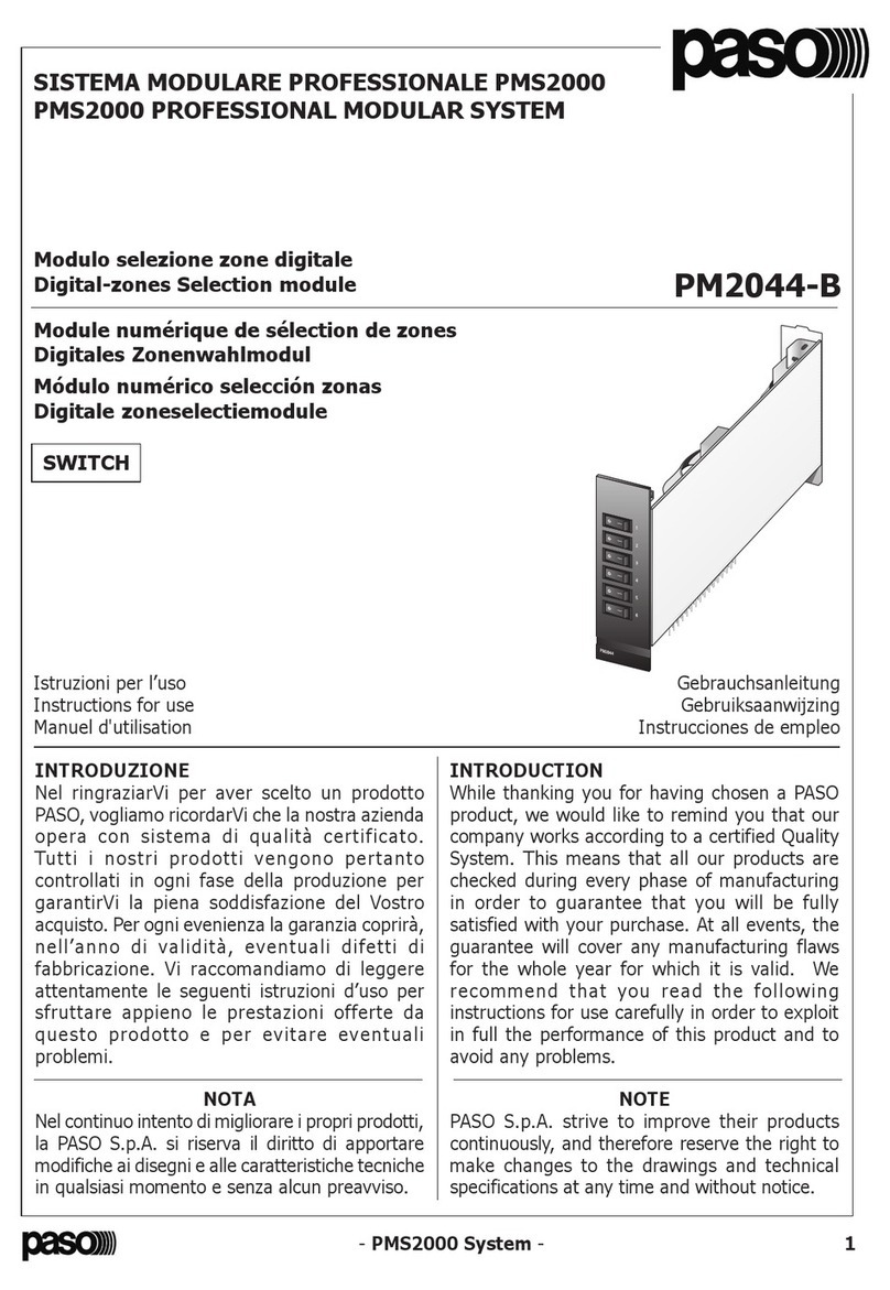
Paso PMS2000 Series User manual

Paso

Paso PMS2000 Series User manual

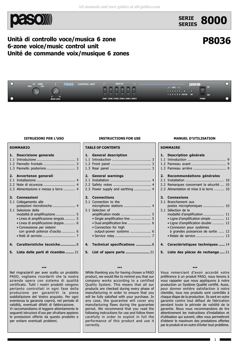
Paso 8000 Series User manual

Paso

Paso 8000 Series User manual

Paso PM2044-B User manual

Paso

Paso PM2044-B User manual

Paso SD200 SYSTEM User manual

Paso

Paso SD200 SYSTEM User manual

Popular Control Unit manuals by other brands

Grundfos MFV quick guide

Grundfos

Grundfos MFV quick guide

Ingersoll-Rand ARO STOP 23644-400 Operator's manual

Ingersoll-Rand

Ingersoll-Rand ARO STOP 23644-400 Operator's manual

DMP Electronics myQ 736Q Installation sheet

DMP Electronics

DMP Electronics myQ 736Q Installation sheet

ELREHA BMR 3002 Brief Instruction

ELREHA

ELREHA BMR 3002 Brief Instruction

Comeval UNIFLOW PP Series Installation, operating and maintenance manual

Comeval

Comeval UNIFLOW PP Series Installation, operating and maintenance manual

Nibe PCM S40 Installer manual

Nibe

Nibe PCM S40 Installer manual

LG LG Q1C-V5 Series installation manual

LG

LG LG Q1C-V5 Series installation manual

Cabletron Systems 6E233-49 SmartSwitch 6000 user guide

Cabletron Systems

Cabletron Systems 6E233-49 SmartSwitch 6000 user guide

Victaulic 769N FireLock NXT Series Installation, Maintenance, and Testing Manual

Victaulic

Victaulic 769N FireLock NXT Series Installation, Maintenance, and Testing Manual

Viconics R820 Series manual

Viconics

Viconics R820 Series manual

Siemens PXC-16 Compact Technical reference manual

Siemens

Siemens PXC-16 Compact Technical reference manual

GEA DHV operating instructions

GEA

GEA DHV operating instructions

Pentair Keystone Figure 952 NPS 2 Disassembly instructions

Pentair

Pentair Keystone Figure 952 NPS 2 Disassembly instructions

Inbal Valves 700D Series manual

Inbal Valves

Inbal Valves 700D Series manual

ExpertDAQ EX-9016 manual

ExpertDAQ

ExpertDAQ EX-9016 manual

Heliodyne Delta T Pro installation guide

Heliodyne

Heliodyne Delta T Pro installation guide

Valcom V-2001 manual

Valcom

Valcom V-2001 manual

DFI CH960-CM246 user manual

DFI

DFI CH960-CM246 user manual

manuals.online logo
manuals.online logoBrands
  • About & Mission
  • Contact us
  • Privacy Policy
  • Terms and Conditions

Copyright 2025 Manuals.Online. All Rights Reserved.