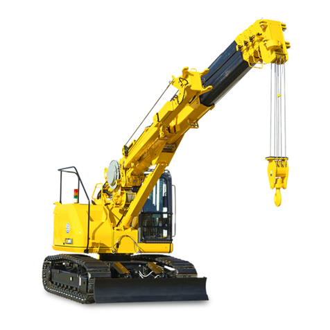
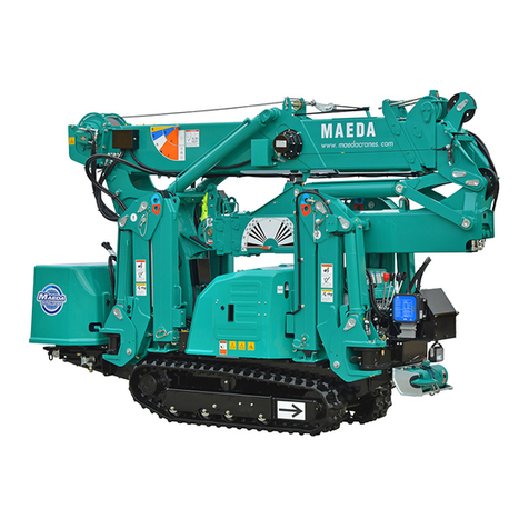
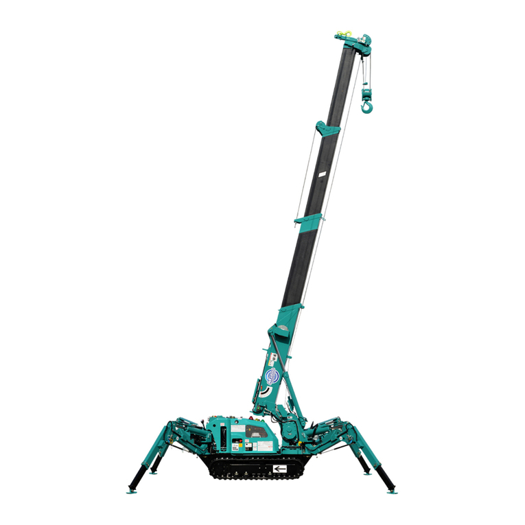
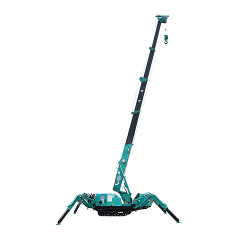
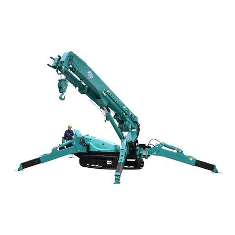
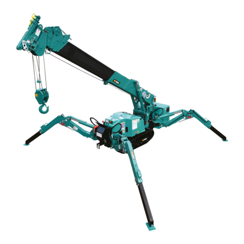
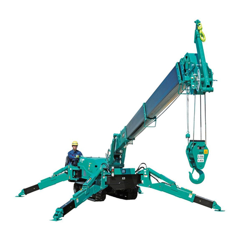
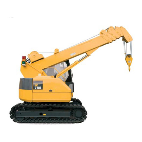
Maeda LC383M-5 User manual

541E-OM1010-00
OPERATION MANUAL
CRAWLER CRANE
Serial No. 11001 and up
Unsafe use of this machine may cause serious injury or death. Operators
must read this manual before operating this machine. This manual should
be kept near the machine for reference and periodically reviewed by all
personnel who will come into contact with it.
NOTICE
MAEDA has Operation Manual written in some other languages. If a foreign
language manual is necessary, contact your local distributor for availability.


0-1
CONTENTS
ITEM Page
INTRODUCTION 1- 1
1. INTRODUCTION 1- 2
2.FOR SAFE USE OF MACHINE 1- 3
3. MACHINE OVERVIEW 1- 4
3.1 SPECIFIED OPERATIONS 1- 4
3.2 MACHINE CONFIGURATION 1- 4
3.3 MACHINE FUNCTIONS 1- 5
4. QUALIFICATION FOR OPERATION 1- 6
4.1 QUALIFICATION FOR CRANE OPERATION 1- 6
5. TERMINOLOGY 1- 7
5.1 DEFINITIONS OF TERMS 1- 7
5.2 DIAGRAM OF WORKING RADIUS AND LIFTING HEIGHT 1- 8
5.3 RATED TOTAL LOAD CHART 1- 9
6. NECESSARY INFORMATION FOR SERVICE 1-12
SAFETY 2- 1
1. BASIC PRECAUTIONS 2- 2
1.1 PRECAUTIONS FOR BEFORE STARTING OPERATION 2- 2
1.2 PREPARARATIONS OF SAFETY OPERATION 2- 3
1.3 PRECAUTIONS FOR FIRE PREVENTION 2- 5
1.4 PRECAUTIONS WHEN GETTING ON OR OFF 2- 6
1.5 OTHER PRECAUTIONS 2- 7
2. DRIVING RELATED PRECAUTIONS 2- 8
2.1 PRECAUTIONS FOR JOBSITE 2- 8
2.2 PRECAUTIONS WHEN ENGINE STARTING 2-11
2.3 PRECAUTIONS WHEN STARTING TO MOVE MACHINE 2-13
2.4 PRECAUTIONS WHEN WORKING WITH CRANE 2-16
3. TRANSPORT PRECAUTIONS 2-24
4. TOWING PRECAUTIONS 2-25
5. MAINTENANCE PRECAUTIONS 2-26
5.1 PRECAUTIONS BEFORE MAINTENANCE 2-26
5.2 PRECAUTIONS DURING MAINTENANCE 2-29
6. SAFETY LABEL LOCATIONS 2-33
OPERATION 3- 1
1. MACHINE EACH SECTION 3- 2
1.1 MACHINE EACH UNIT 3- 2
1.2 OPERATOR’S COMPARTMENT EQUIPMENT 3- 3
1.3 MOMENT LIMITER RELATED SWITCH BOX 3- 4

0-2
ITEM Page
2. EXPLANATION OF DEVICES 3- 5
2.1 MACHINE MONITOR 3- 5
2.1.1 EMERGENCY STOP ITEMS 3- 6
2.1.2 GAUGE AND METER 3- 8
2.1.3 PILOT DISPLAY 3-10
2.2 SWITCHES 3-11
2.3 MOMENT LIMITER (OVERLOAD DETECTOR ) 3-14
2.3.1 MOMENT LIMITER CONFIGURATION 3-14
2.3.2 FUNCTION OF MOMENT LIMITER 3-15
2.3.3 MOMENT LIMITER OPERATIONS 3-17
2.3.4 NAMES OF MOMENT LIMITER DISPLAY UNIT 3-19
2.3.5 MOMENT LIMITER FUNCTIONS 3-28
2.3.6 MOMENT LIMITER STARTING STATUS 3-30
2.3.7 MOMENT LIMITER WORKING ENVELOPE SETTING 3-30
2.3.8 PICK & CARRY/STAITIONARY MODE SELECT SWITCH 3-31
2.3.9 MOMENT LIMITER EMERGENCY STOP CANCEL SWITCH 3-32
2.3.10 MOMENT LIMITER CAUSES OF ERRORS AND ACTIONS TO BE TAKEN 3-33
2.4 OVER HOIST DETECTOR 3-34
2.5 CONTROL LEVERS AND PEDALS 3-35
2.6 COVERS WITH LOCK 3-40
2.7 ENGINE HOOD 3-41
2.8 FUSES 3-43
2.9 FUSIBLE LINK 3-44
2.10 OPERATION MANUAL STORAGE 3-44
2.11 GREASE GUN HOLDER 3-44
2.12 POWER SUPPLY FOR OPTIONS 3-45
3. MACHINE OPERATIONS AND CONTROLS 3-46
3.1 CHECKING/ADJUSTING BEFORE STARTING ENGINE 3-46
3.1.1 VISIBLE CHECKS 3-46
3.1.2 CHECKING BEFORE STARTING (CHECKING BEFORE OPERATION) 3-49
3.1.3 OPERATIONS/CHECKING BEFORE STARTING ENGINE 3-59
3.1.4 CHECKING AFTER STARTING ENGINE 3-61
3.2 STARTING ENGINE 3-64
3.2.1 NORMAL STARTING ENGINE 3-64
3.2.2 STARTING ENGINE IN COLD WEATHER 3-65
3.3 OPERATIONS AFTER STARTING ENGINE 3-67
3.3.1 ENGINE WARM-UP OPERATION 3-67
3.4 STOPPING ENGINE 3-69
3.5 BREAKING-IN MACHINE 3-70
3.6 MACHINE TRAVELING POSTURE 3-71

0-3
ITEM Page
3.7 STARTING/MOVING/STOPPING MACHINE 3-72
3.8 STEERING MACHINE 3-76
3.9 SWINGING 3-78
3.10 CAUTIONS BEFORE OPERATING THE CRANE 3-79
3.11 OPERATIONS BEFORE OPERATING THE CRANE 3-80
3.12 CRANE OPERATION POSTURE 3-82
3.13 HOOK RAISING/LOWERING OPERATION 3-83
3.13.1 NORMAL HOOK RAISING/LOWERING OPERATION 3-83
3.13.2 HOOK RAISING OPERATION BY HOOK STOWAGE SWITCH 3-84
3.14 BOOM DERRICKING OPERATION 3-85
3.15 BOOM TELESCOPING OPERATION 3-86
3.16 SWING OPERATION 3-87
3.17 STOWAGE OPERATION OF CRANE 3-88
3.17.1 CRANE OPERATION FOR TEMPORARY HOOK BLOCK STOWAGE 3-88
3.17.2 CRANE OPERATION FOR REGULAR HOOK BLOCK STOWAGE 3-91
3.18 DO’S AND DON’TS DURING OPERATION 3-93
3.19 PICK AND CARRY OPERATION 3-95
3.19.1 SAFETY PRECAUTIONS FOR PICK AND CARRY OPERATION 3-95
3.19.2 POSTURE FOR PICK AND CARRY OPERATION 3-96
3.19.3 OPERATIONS DURING PICK AND CARRY OPERATION 3-97
3.19.4 RELEASING PICK AND CARRY OPERATION POSTURE 3-97
3.20 OPERATION OF BLADE 3-98
3.20.1 PRECAUTION OF BLADE OPERATION 3-98
3.20.2 OPERATION OF BLADE 3-99
3.20.3 WORKING WITH A BLADE 3-99
3.21 PARKING MACHINE 3-100
3.22 MACHINE INSPECTION AFTER DAILY WORK 3-101
3.22.1 BEFORE STOPPING ENGINE 3-101
3.22.2 AFTER STOPPING ENGINE 3-101
3.22.3 LOCKING 3-101
3.23 CAUTIONS IN TRAVELING 3-102
4. HANDLING WIRE CABLES 3-104
4.1 BENCHMARK FOR REPLACING WIRE CABLES 3-104
4.2 WINCH WIRE CABLE FALL MODE AND RATED TOTAL LOAD 3-106
4.3 WHAT TO DO WITH TWISTED WINCH WIRE CABLE 3-107
5. TRANSPORTATION 3-110
5.1 LOADING/UNLOADING 3-111
5.1.1 LOADING 3-112
5.1.2 SECURING MACHINE 3-114
5.1.3 UNLOADING 3-115

0-4
ITEM Page
5.2 LIFTING MACHINE 3-116
5.2.1 LIFTING THE MACHINE IN THE BOOM LOWERED POSTURE 3-116
5.2.2 LIFTING THE MACHINE IN THE BOOM RAISED POSTURE 3-118
6. HANDLING IN COLD WEATHER 3-120
6.1 PREPARING FOR LOW TEMPERATURE 3-120
7. LONG TERM STORAGE 3-123
7.1 BEFORE STORING IT MACHINE 3-123
7.2 DURING STORAGE 3-123
7.3 AFTER STORAGE 3-123
8. TROUBLES AND ACTIONS 3-124
8.1 RUNNING OUT FUEL 3-124
8.2 PHENOMENA THAT ARE NOT FAILURES 3-124
8.3 TOWING THE MACHINE 3-125
8.4 DISCHARGED BATTERY 3-125
8.4.1 CAUTIONS IN BATTERY HANDLING 3-125
8.4.2 BATTERY REMOVAL AND INSTALLATION 3-126
8.4.3 CAUTIONS IN BATTERY CHARGING 3-127
8.4.4 STARTING ENGINE WITH BOOSTER CABLE 3-128
8.4.5 STARTING ENGINE 3-129
8.5 OTHER TROUBLE 3-130
8.5.1 ELECTRICAL COMPONENTS 3-130
8.5.2 CHASSIS 3-130
8.5.3 ENGINE 3-131
8.5.4 MOMENT LIMITER 3-132
8.5.5 OVER HOIST DETECTOR 3-132
INSPECTION AND MAINTENANCE 4- 1
1. PRECAUTIONS REGARDING MAINTENANCE 4- 2
2. BASIC MAINTENANCE 4- 4
3. LEGAL INSPECTION 4- 7
4. PERIODIC REPLACEMENT OF SAFETY CRITICAL PARTS 4- 8
5. CONSUMABLES 4- 9
6. OTHER COMPONENTS 4-10
7. USE OF FUEL, COOLANT AND LUBRICANT 4-11
7.1 USE OF FUEL, COOLANT AND LUBRICANTS ACCORDING TO AMBIENT
TEMPERATURES 4-11
8. TIGHTENING TORQUE SPECIFICATIONS 4-13
8.1 STANDARD TIGHTENING TORQUE LIST 4-13
9. INSPECTION AND MAINTENANCE LIST 4-14

0-5
ITEM Page
10. MAINTENANCE PROCEDURES 4-16
10.1 INITIAL 500 HOUR MAINTENANCE 4-16
10.2 CHECKING BEFORE OPERATION 4-16
10.3 IRREGULAR MAINTENANCE 4-17
10.4 MAINTENANCE EVERY 50 HOURS 4-36
10.5 MAINTENANCE EVERY 100 HOURS 4-38
10.6 MAINTENANCE EVERY 250 HOURS 4-39
10.7 MAINTENANCE EVERY 500 HOURS 4-41
10.8 MAINTENANCE EVERY 1000 HOURS 4-46
10.9 MAINTENANCE EVERY 1500 HOURS 4-48
10.10 MAINTENANCE EVERY 2000 HOURS 4-49
SPECIFICATIONS 5- 1
1. SPECIFICATION LIST 5- 2
2. SPECIFICATION DIMENSIONAL DRAWING 5- 3
3. RATED TOTAL LOAD CHART 5- 4
4. WORKING RADIUS AND LIFTING HEIGHT 5- 7
SEARCHER HOOK 6- 1
1. SEARCHER HOOK EACH SECTION 6- 2
2. MOMENT LIMITER DISPLAY UNIT 6- 3
3. OPERATION 6- 5
4. INSPECTION AND MAINTENANCE 6- 8
4.1 LEGAL INSPECTION 6- 8
4.2 CONSUMABLES 6- 8
4.3 INSPECTION AND MAINTENANCE LIST 6- 8
4.4 MAINTENANCE PROCEDURES 6- 9
4.4.1 INSPECTION OF BEFORE OPERATION 6- 9
5. WORKING RADIUS AND RATED TOTAL LOAD 6-11
5.1 WORKING RADIUS AND LIFTING HEIGHT FOR SEARCHER HOOK 6-11
5.2 RATED TOTAL LOAD CHART FOR SEARCHER HOOK 6-12

0-6

1-1
INTRODUCTION
1. INTRODUCTION 1- 2
2. FOR SAFE USE OF MACHINE 1- 3
3. MACHINE OVERVIEW 1- 4
4. QUALIFICATION FOR OPERATION 1- 6
5. TERMINOLOGY 1- 7
6. NECESSARY INFORMATION FOR SERVICE 1-12

1-2
1. INTRODUCTION
Thank you for purchasing our Crawler Crane “LC383M-5”.
This manual is a guidebook for safe and effective use of this machine.
This manual describes the procedures for proper operation and maintenance of the machine.
Warnings and precautions defined in this manual shall be observed for safety.
Many of the accidents are caused by failure to observe the basic precautions for operation,
inspection and maintenance.
Be sure to read this manual and understand the procedures for machine operation,
inspection, and maintenance thoroughly before performing any operation of this machine.
Failure to observe the basic precautions defined in this manual may lead to hazardous
accidents.
Failure to use this machine properly can lead to serious personal injury or death.
Operators and maintenance personnel must always read this manual prior to
operation or maintenance of this machine.
Keep this manual at a designated place for reference when necessary. All
personnel who work with this machine are to carry out periodic reference to the
manual.
•Only those who have a thorough understanding of the fundamental procedures
provided in this manual are allowed to operate this machine.
•Keep this manual handy for reference when necessary.
•Should you lose or damage this manual, contact Maeda or our sales service
agency immediately for ordering a new manual.
•This manual should always accompany this machine upon transfer of the machine
to the next owner. However, when the machine is sold to a third party without any
prior advice to us, we are not liable for any warranty.
•This manual has adopted data that was available at the time of the creation of the
manual.
The contents of this manual, including maintenance specifications, tightening
torque, pressure, measuring method, adjustment value, and illustrations, are
subject to change without notice.
Machine maintenance may be subject to revisions. Always obtain the latest
information from Maeda or our sales service agency before performing
maintenance of this machine.
For safety instructions, see “2. For Safe Use of Machine” on page 1-3 and “Safety”
on page 2-1.
[Storage location for the Operation and Maintenance Manual]
Magazine pocket on the back of operator’s seat
1-3
2. FOR SAFE USE OF MACHINE
This manual classifies the risks into the following three categories to present the details of the safety
labels in a easy-to-understand manner.
This denotes that there is an imminent hazard which will cause serious
personal injury or death.
The method of hazard circumvention is stated.
This denotes that there is a hazard which can cause serious personal injury
or death.
The method of hazard circumvention is stated.
This denotes that there is a potential hazard which may cause minor or
moderate personal injury or serious damage to this machine.
The method of hazard circumvention is stated.
This manual also provides the following to indicate what must be observed for the sake of the machine
and what will be of help.
This denotes that failure to handle the machine properly may damage the
machine or shorten its life.
This denotes helpful information.
Not only procedures for operation, inspection, and maintenance of this machine described in this manual
but also safety precautions that may pertain to the case where this machine is only used for specified
tasks.
Every circumstance incidental to use of this machine is unforeseeable, and therefore, cautions given in
this manual and on this machine do not necessarily cover every safety-related issue.
Necessary safety actions should be taken under your responsibility if operation, inspection, and
maintenance in a situation that is not described in this manual are performed.
Even in the above case, never attempt work or operations that this manual prohibits doing.
CAUTION
NOTES

1-4
3. MACHINE OVERVIEW
3.1 SPECIFIED OPERATIONS
This machine is for use with the operations listed below.
•Crane operation
•Pick & Carry operation
This machine is a mobile crane which consists of a crawler type carrier and an upper structure of a boom
type crane.
This self-propelled crane is capable of moving (travelling) at the worksite and lifting an object weighing
within the rated total load for normal crane operation or pick and carry operation.
3.2 MACHINE CONFIGURATION
(1) Undercarriage
(2) Upper structure
(3) Safety device
In this manual, the terms front, rear, left and right refer to the travel
direction as viewed from the operator’s seat when the operator’s seat
is facing the front and the sprocket (a) is at the rear of the machine.
Boom slewing motion is determined with the machine viewed from
immediately above; slew clockwise denotes right-handed motion and
slew counterclockwise denotes left-handed motion.
EXTERNAL VIEW

1-5
This machine is comprised of the units listed below.
[1] UNDERCARRIAGE
This is comprised of a travelling gear and blade.
[2] UPPER STRUCTURE (CRANE)
This is comprised of an engine, travelling operation unit, crane operation unit, telescoping system, derrick
system, slewing system, hook block, and winch system.
[3] SAFETY DEVICE
This is comprised of the following parts and devices: Over hoist detector/automatic stop device,
three-winding stop alarm/automatic stop device, moment limiter (working envelope limited), slinging rope
detachment protector, hydraulic safety valve, telescoping cylinder hydraulic automatic locking device,
derricking cylinder hydraulic automatic locking device, alarm buzzer, machine tip-over alarm device, level,
working status lamp, crane lock lever and travel lock bar.
3.3 MACHINE FUNCTIONS
[1] UNDERCARRIAGE
• The carrier is equipped with crawlers which enables this machine to enter into rough or soft terrain.
• 2 travel lever operation enables not only direction changes, forward, backward, and right/left but pivot
and spin turns.
[2] UPPER STRUCTURE (CRANE)
• The upper structure allows continual 360 degree rotation.
• Due to extending/retracting, derricking up or down and/or swing operations of the boom, as well as raise
and lower operation of the winch, you can move the hoisted load to the designated location, subject to
staying within the rated total road and working radius.

1-6
4. QUALIFICATION FOR OPERATION
•A high incidence of occupational accidents during crane operation are reported.
Be aware that experienced engineers are no exception.
•Warnings and precautions defined in this manual shall be observed for safety assurance
during operation of the machine.
4.1 QUALIFICATION FOR CRANE OPERATION
Only personnel that have obtained the required license or training stipulated by laws and regulations
applicable to the place of use are qualified to operate this machine.
Contact the relevant government office or our sales service agency for further information.

1-7
5. TERMINOLOGY
5.1 DEFINITIONS OF TERMS
[1] RATED TOTAL LOAD
This is the maximum load that can be applied according to
boom length and angle. The load includes the mass (weight)
of hoisting accessories (hooks) slings, chains and ropes etc.
[2] LIFTED LOAD
This is a load derived by subtracting the mass (weight) of
hoisting accessories (hooks) and sling etc, from the rated total
load, which is a maximum load for hoisting.
[3] WORKING RADIUS
This is a horizontal distance between the axis of slewing and
the hook center.
[4] BOOM LENGTH
This is a distance between the boom primary pin and the
sheave pin of the end boom.
[5] BOOM ANGLE
This is an angle which the boom forms from horizontal.
[6] LIFTING HEIGHT ABOVE GROUND
This is a vertical distance between the hook bottom and the
ground with the hook raised to the upper limit.

1-8
5.2 DIAGRAM OF WORKING RADIUS AND LIFTING HEIGHT
•The diagram of working radius and lifting height shows the relationships the working radius of
this machine, boom angle, and lifting height above the ground with no object hoisted. The
diagram has been made allowing for no deflection in the boom.
•The boom (3) in the diagram of working radius and lifting height represents a state that half of
the “
mark” passes boom (2).
1. Point A denotes a boom angle and point B denotes a lifting
height above ground in the figure at right.
The same working radius is applied to points A and B.
2. The “diagram of working radius and lifting height” shows the
relationships of the working radius, boom angle, and lifting
height at no load, allowing for no deflection in the boom.
A deflection occurs in the boom when an object is hoisted,
which causes the working radius to increase slightly.
The rated total load decreases with an increase in the
working radius. Actual crane operation requires the planning
of work, allowing for sufficient tolerance of more than that
shown in the diagram.

1-9
5.3 RATED TOTAL LOAD CHART
•All the values provided in the rated total load chart are based on the assumption that the
machine is placed on a level and firm surface.
•The values in the rated total load chart are determined based on the working radius allowing
for deflection that is developed when load is applied to the boom.
•When extending boom (2) even if only slightly, crane operation should proceed to the extent of
performance of “Boom (2)”.
•When extending boom (3) even if only slightly, crane operation should proceed to the extent of
performance of “Boom (3)”.
•When half of the “
mark” on boom (3) passes boom (2), crane operation should proceed to
the extent of performance of “Boom (4)”.
•If the working radius exceeds that stated in the table even if only slightly, crane operation
should proceed with respect to the rated total load corresponding to the working radius in the
following table.
•The rated total load is a load including the mass of a hoisting accessory (hook: 30kg).
Maeda, Please check 8.71m Boom on above chart, it
should say Stationary and not Pick and Carry
LC383M-5 Rated Total Load Chart
3.18m boom 5.03m boom 6.87m boom 8.71m boom
Working radius
(m) Stationary Pick & Carry Stationary Pick & Carry Stationary Pick & Carry
1.50 2930 1465 2930 1465 1870 1190
2.00 1730 865 1710 855 1710 1190
2.50 1200 600 1190 595 1190 1190
2.85 980 490 980 490 980 980
3.00 900 450 900 900
3.50 720 360 720 720
4.00 600 300 600 600
4.50 500 250 500 500
4.70 460 230 460 460
5.00 430 430
5.50 370 370
6.00 330 330
6.54 290 290
7.00 260
7.50 235
8.00 215
8.38 200
Boom Angle(°) 0~42.9 0~64.2 0~72.3 0~76.5

1-10
The rated total load chart provides the maximum loads that the crane is capable of hoisting objects in
parallel with the length of the boom. The loads are specified by working radius.
[1] BOOM LENGTH
The following figures illustrate the condition of the booms, “(1) 3.18m Boom”, “(2) 5.03m Boom”, “(3)
6.87m Boom”, and “(4) 8.71m Boom” in the preceding boxes in the rated total load chart.
1. “(1) 3.18m Boom”: All the booms are retracted.
2. “(2) 5.03m Boom”: With booms (3), and (4) retracted, boom (2) is fully extended.
Boom (2) is to apply to crane operation with boom (2) extended even if only slightly.
3. “(3) 6.87m Boom”: With boom (2) fully extended, booms (3) and (4) are extended midway (half of the
“
mark” passes boom (2)).
Boom (3) is to apply to crane operation with booms (3) and (4) extended even if only slightly.

1-11
5. “(4) 8.71m Boom”: All the booms are fully extended.
Boom (4) is to apply to crane operation with half of the “
mark” on boom (3) passes boom (2).

1-12
6. Necessary information for service
The following information is required for us or our sales service agency at the time of requesting repair
service or ordering spare parts.
Machine serial number engraved on plate
Located at the lower right part of canopy.
Engine serial number engraved on plate
Located on the top of engine cylinder head cover.
Table of contents
Other Maeda Construction Equipment manuals

Maeda
Maeda MC405C-3 User manual

Maeda
Maeda MC-285C User manual

Maeda
Maeda MC174 User manual

Maeda
Maeda MC-285C User guide

Maeda
Maeda MC815C User guide

Maeda
Maeda LC1385M-8B User manual

Maeda
Maeda MC285CB-3 User manual

Maeda
Maeda MC-104C-2 User manual

Maeda
Maeda MC305C-3 User manual

Maeda
Maeda CC1908S-1 User manual

Maeda
Maeda MC405C-3 User manual

Maeda
Maeda MC285C-2 User manual

Maeda
Maeda LC785M-8B User manual

Maeda
Maeda CC1908S-1 User manual

Maeda
Maeda MC815C User manual

Maeda
Maeda MC-174CRM User manual

Maeda
Maeda LC1385M-8BF User manual

Maeda
Maeda LC785M-6B User manual

Maeda
Maeda MC-174CRM User manual

Maeda
Maeda MC-305C-2 User guide