PATROLLINE HPS 845 User manual

Page 1 of 16 HPS 845 R.7 COD:00-99-0I84505 (000)
HPS 845
Can bus alarm system
Thank you for choosing one of our products
THIS INSTRUCTION MANUAL IS VALID FOR SYSTEMS WITH CARLIST34 OR
HGHER. IT INTEGRATES THE NEW WIRELESS SIREN SUPPORT
For "CARLISTxx" means the list of compatible vehicles preloaded into memory (see label report on the control
unit. Each update adds new vehicles, while maintaining compatibility with earlier Carlists. for compatibility see
application list HPS-845 on www.vos.be .
I
IN
ND
DE
EX
X
O
OF
F
M
MA
AN
NU
UA
AL
L
Read and keep this manual in the vehicle, the may be helpful in case of need, maintenance, vehicle
sale, of the safety features expansions etc. Inside you will find:
USER SECTION
INSTALLER SECTION
MAINTENANCE, TECHNICAL, CONFORMITY
WARRANTY SECTION
page 2-8
Page 9-14
Page 15
Page 16
P
PA
AC
CK
KA
AG
GE
E
C
CO
ON
NT
TE
EN
NT
TS
S
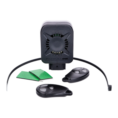
Supplied in standard version are:
•HPS 845: central unit
•Programming button
•Indication LED
In the HPS-868 kit are included:
•HPS-845: central unit
•HPS-55: adjustable ultrasonic module
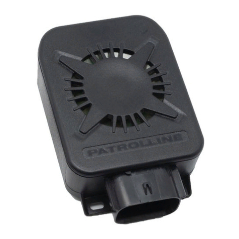
•HPS-98: wireless siren.
•Programming button
•Indication LED

Page 2 of 16 HPS 845 R.7 COD:00-99-0I84505 (000)
User section
D
DE
ES
SC
CR
RI
IP
PT
TI
IO
ON
N
O
OF
F
T
TH
HE
E
S
SY
YS
ST
TE
EM
M
The system is able to interface and acquire information through the CAN BUS (Controller
Area Network) of the vehicle. It then uses radio controls and / or transponder of the
vehicle set for its own operation.
And 'possible to find information at www.vos.be site and downloading the vehicle specific
installation manual.
Inside the alarm memory reside all compatible vehicles, the selection is done through the
position of switches 1 and 2 on the control unit.
Vehicle selection 01 is dedicated to vehicles not equipped with a CAN bus suitable
system. Connecting appropriately the wires (see the connection diagrams of the vehicle) it
can get its operation in the traditional analog version.
HPA974 – Transmitter (optional)
In addition to use with the original remote control of the car it is possible to add one or
more transmitters HPA 974, which can act both in synchronous with the originals, both
independently for greater safety. (see functions n°5 and n°26 to p.16).
HPA 977 – Transponder (optional)
With the addition of a transponder is possible to manage transparently the special security
functions (v. functions 10, 11 and 27 to p.16). The functions are still manageable through
the panic button present in the package.
HPA 975 – Wireless sensor (optional)
It is possible to extend the protection of the system with the addition of wireless sensors
2.4 GHz (HPA 975)
HPS 98 - Self-powered wireless siren (optional)
It allows faster installation by eliminating the passage of cables in the engine
compartment.
OPTIONAL DEVICE TO IMPROVE SAFETY AND FUNCTIONALITY
Switches vehicle
See the application list at
www.vos.be for the
positions of the rotation
switches.
1 2

Page 3 of 16 HPS 845 R.7 COD:00-99-0I84505 (000)
User section
O
OR
RI
IG
GI
IN
NA
AL
L
R
RE
EM
MO
OT
TE
E
C
CO
ON
NT
TR
RO
OL
L
O
OP
PE
ER
RA
AT
TI
IN
NG
G
ARMING: PRESS THE LOCKING BUTTON ON THE ORIGINAL REMOTE CONTROL ONCE
TO LOCK THE VEHICLE AND ARM THE ALARM.
CONFIRMED BY:
•1 beep (if enabled);
•The LED on the dashboard turn ON;
•Engine block ON (if connected);
•Modules output arming (Windows lifter, ultrasonic, etc.);
The second press of the lock button allows disabling of ultrasound sensors,
wireless devices in Zone 2 and the rise of windows (if connected). This
function is subordinate to the vehicle type. If the second pressure NOT run
the exclusion perform the sequence "Lock - Unlock - Block" of the original
central locking with remote control in quick succession. The exclusion is
confirmed by 4 led blinks before posting.
DISARMING: PRESS THE UNLOCKING BUTTON ON THE ORIGINAL REMOTE CONTROL
ONCE TO UNLOCK THE VEHICLE AND DISARM THE ALARM.
CONFIRMED BY:
•2 beeps (if enabled);
•Turning off the LED on the dashboard;
•Deactivation of electric engine immobilization (if connected).;
•Deactivation of modules output (windows lifter, ultrasonic, etc.);
After disarming, in the case of one or more alarm cycles, the LED will
remain fixe, indicating the presence of the alarm memory, that will be
displayed after opening the door. To stop it turn on the key.
PRESSING THE TRUNK RELEASE OF ORIGINAL REMOTE CONTROL
If the alarm is on it will inhibit all excludible sensors, volumetric sensors
and trunk detection to allow the access to the luggage compartment. The
physical closing of the trunk will re-enable the sensors. This function could
be dependent of the vehicle used.
S
ST
TA
AT
TU
US
S
L
LE
ED
D
O
OF
F
T
TE
E
S
SY
YS
ST
TE
EM
M
(
(L
LE
ED
D
O
ON
N
T
TH
HE
E
D
DA
AS
SH
HB
BO
OA
AR
RD
D)
)
LED indication
Function
-OFF
Power off or system disarmed
-
½ sec. ON - ½ sec. OFF
First power up or restart for power failure. Perform an opening and closing
cycle to turn it off
-
ON fixe
Neutral time 10 sec. (after insertion) or alarm memory ready for reporting
(after system disarmed). Open the driver's door and count the flashes of
the LED between a pause and the next. Check the sensor intervened in
the "Alarm Memory" paragraph
-Flash every second
System inserted and in surveillance
-ON 2 sec. and OFF 1
sec.
Car selected not in memory, check the set selection and if properly update
the unit.
-Quick flashing, 5 times
per sec.
Alarm in progress. The cycle lasts 30 seconds.
-
2 flashes and pause
VALET function is active, system blocked, this signaling occurs at ignition
key on and is repeated for 40 seconds (see VALET function).
-Quickly flashes (3
time/sec) only after
disarming
The IMMOBILIZER function (n° 27) is active. It’s necessary to disarming
with the reset pushbutton (if the transponder is not present) or the
system make alarm.
-Flashing very fast, 10
times per sec.
The device firmware is corrupted, it tried to load the firmware of another
product, update the system via PC using the correct file.

Page 4 of 16 HPS 845 R.7 COD:00-99-0I84505 (000)
User section
H
HP
PA
A
9
97
74
4
-
-
R
RE
EM
MO
OT
TE
E
C
CO
ON
NT
TR
RO
OL
L
O
OP
PE
ER
RA
AT
TI
IO
ON
N
(
(O
OP
PT
TI
IO
ON
NA
AL
L)
)
In addition to the same functions as the original remote control, through the bi-directional
transmission, the transmitter HPA 974 has useful diagnostic and control functions.
S
SO
OU
U
BUTTON 3
Arming system
The entry is confirmed by:
- 1 beep (if enabled)
- 1 arrows flash (if enabled)
- LED on the dashboard
- Lock the doors (if connected)
- Activation of electric engine immobilization
(if connected)
- Activation of modules output (windows
lifter, ultrasonic, etc.)
- Enhanced output activation (electric
windows, etc.)
Press again within 10 seconds to rule the
ultrasound and radio sensors in zone 2. The
exclusion will be confirmed by 3 beeps and 3
flashes arrows.
BUTTON 1
Disarming system
Disarming is confirmed by:
- 2 beeps (if enabled)
- 2 flashing blinker (if enabled)
- Turning off the LED on the dashboard
- Unlock the doors (if connected)
- Deactivation of electric engine
immobilization (if connected)
- Deactivate output modules (ultrasound,
etc.)
After disarming, in the case of one or more
alarm cycles, the LED will display the alarm
memory after the opening of the door until
turn on the key.
BUTTON 1+2
Exclusion zone 2 sensors
Simultaneously pressing buttons 1 and 2
(after 10 sec. of the insertion system)
for excluding the alarm signal of the
programmed sensors in zone 2.
The exclusion is confirmed by 6 beeps
and 6 flashes blinkers.
BUTTON 1+3
System status
Press simultaneously and release
them. If the transmitter LED will flash
for a few seconds, the alarm is
inserted. If the alarm is off, the LED
will remain off.
The function is independent of the
distance from the vehicle and is valid
when you use the same remote
control for alarm management.
LED
While pressing any of the
radio button if the LED:
Is fixe: means
that the transmission is
received by the system.
Blinks fast: means that the
transmission is not received
by the system (distance too
great).
Blinks 4 times: it means
that the transmitter battery
is low and it should be
replaced.
BUTTON 2
Panic alarm and siren stop
- The pressure of the button 2
when the system is armed
causes an alarm cycle (and
therefore the sound) for about
30 sec.
If the system is already in
alarm, this is stopped.
- Pressing the button 2 after 10
sec. of the insertion causes the
exclusion of the siren,
confirmed by 4 beeps and 4
flashes blinkers.

Page 5 of 16 HPS 845 R.7 COD:00-99-0I84505 (000)
User section
S
SE
EC
CU
UR
RI
IT
TY
Y
G
GU
UA
AR
RD
DS
S
A
AN
ND
D
T
TR
RA
AN
NS
SP
PO
ON
ND
DE
ER
R
H
HP
PA
A9
97
77
7
U
US
SE
E
(
(O
OP
PT
TI
IO
ON
NA
AL
L)
)
The IMMOBILIZER functions, ANTI-AGGRESSION and ANTI-THEFT ARE
NOT ACTIVE in the default configuration. Their activation can be done
exclusively on the customer's request and only by qualified personnel.
Warning this function are managed by the transponder device (HPA977)
or by the RESET Pushbutton (that must be installed)
Button RESET and HPA 977
I
IM
MM
MO
OB
BI
IL
LI
IZ
ZE
ER
R
F
FU
UN
NC
CT
TI
IO
ON
N
(
(N
N°
°
2
27
7)
)
This function, if programmed, is activated when you switched off the alarm.
From this moment and within 30 sec. the function must be reset by the presence of the
transponder or the appropriately installed RESET button. If not, a full alarm cycle with
starts with engine block. The ignition ON skips the timeout and trigs a direct alarm
cycle with engine block.
Also, the opening of any doors after 15 sec. starts a direct alarm cycle.
If the function is started you can re-arm the system by remote control or with vehicle
self locking.
CAUTION: disarming the alarm (unlocking with original remote control) out of
the range of the transponder, after 30 seconds trigs an audible and visual
alarm cycle.
A
AN
NT
TI
I-
-A
AG
GG
GR
RE
ES
SS
SI
IO
ON
N
F
FU
UN
NC
CT
TI
IO
ON
N
(
(N
N°
°
1
10
0)
)
-Can bus vehicle. The vehicle speed, after the ignition key turn ON, controls the
activation and the engine block of the ANTIAGGRESSION function. The alarm system
will request the Transponder recognition after passing the 10km/h speed threshold and,
if the system cannot detect the recognition, after 40 seconds, the alarm system actives
the siren sound for 20 seconds (pre-alarm), form now if the vehicle speed falls below
the 10 km/h speed threshold (settable), the engine block will be activated.
-No Can bus vehicle. Turn ON the key, the procedure start, the LED start to flash.
After 40 seconds, the alarm system actives the siren sound for 20 seconds (pre-alarm),
after that it will stop the engine by the intermittent activation within 50 seconds.
The ANTIAGGRESSION procedure can be stopped every time by the anti theft push
button or by the HPA 977 Transponder signal recognition.
A
AN
NT
TI
I
–
–T
TH
HE
EF
FT
T
F
FU
UN
NC
CT
TI
IO
ON
N
(
(N
N°
°
1
11
1)
)
-Can bus vehicle. The vehicle speed, after the driver door open and close, controls
the activation and the engine block of the ANTIAGGRESSION function. The alarm
system will request the Transponder recognition after passing the 10km/h speed
threshold and, if the system cannot detect the recognition, after 40 seconds, the alarm
system actives the siren sound for 20 seconds (pre-alarm), form now if the vehicle
speed falls below the 10 km/h speed threshold (settable), the engine block will be
activated.
-No Can bus vehicle. Engine is ON, open and close the door checked, the
procedure start, the LED start to flash. After 40 seconds, the alarm system actives the
siren sound for 20 seconds (pre-alarm), after that it will stop the engine by the
intermittent activation within 50 seconds.
The ANTI THEFT procedure can be stopped every time by the anti theft push button or
by the HPA 977 Transponder signal recognition.

Page 6 of 16 HPS 845 R.7 COD:00-99-0I84505 (000)
User section
N
NE
EU
UT
TR
RA
AL
L
T
TI
IM
ME
E
A
AN
ND
D
A
AL
LA
AR
RM
M
S
ST
TA
AT
TU
US
S
Once the signaling of arming is over, the alarm will stay for 10 seconds into “neutral time” condition,
signaled by the fixed light of the LED. The flashing of the LED of the dashboard will indicate that the
system supervises the vehicle and is ready to signal the alarms.
If, during the neutral time, 10 seconds, the alarm system detect a cause of alarm, it shows this by the
blinker flashing. The number of the blinker flashing tell to you the cause of alarm. Look at the table on
chapter “alarm memory” to know the cause.
If the alarm detects the same cause of alarm for 5 times, it excludes automatically this cause.
P
PA
AN
NI
IC
C
A
AL
LA
AR
RM
M
Alarm armed, 10 second after arming, press the LOCKING push- button of the original remote control or
the Button 2 of the PATROLLINE remote control HPA 974: central unit do an alarm cycle that during
about 30 seconds. To stop the alarm cycle, press again the LOCKING push- button of the original
remote control or the Button 2 of the PATROLLINE remote control HPA 974.
These functions are available only for some vehicles, because they depend from the model and the
logical of the original remote control of the car.
A
AD
DD
DI
IT
TI
IO
ON
NA
AL
L
M
MO
OD
DU
UL
LE
E
E
EX
XC
CL
LU
US
SI
IO
ON
N
After the system arming, press the LOCKING push-button of the original remote control or the button
N°3 of the PATROLLINE remote control within 10 seconds.
The exclusion will be confirmed by 3 bip and 3 blinkers flashes.
T
TR
RU
UN
NK
K
O
OP
PE
EN
NI
IN
NG
G
The system can detect the trunk unlocking by the original remote control. In this case, when the trunk
will physical open, the ultrasonic sensor and shock sensor will be disarmed, to avoid the alarm trigger.
These protections will be armed again, when the trunk will physical close.
These functions are available only for some vehicles, because they depend from the model and the
logical of the original remote control of the car.
S
ST
TA
AT
TU
US
S
M
ME
EM
MO
OR
RY
Y
If during the armed state, the alarm is turned off using the mechanical key or the alarm is detached from
the cable harness, after restoration it will remember the state in which it was. This prevents any
tampering attempt.
H
HO
OR
RN
N
/
/
S
SI
IR
RE
EN
N
E
EX
XC
CL
LU
US
SI
IO
ON
N
Through the ignition key it is possible to exclude the HORN / SIREN: alarm disarmed, (CDL opened), turn
on and off the ignition key for 3 times and, within 30 second, press the original remote control to close
the CDL of the vehicle.
Trough the PATROLLINE remote control HPA 974, is possible to exclude the HORN / SIREN: after system
arming, within the first 10 seconds, push the Button2 of the PATROLLINE remote control. The exclusion
will be confirmed by 4 blinkers flashes and 4 beeps.
From this moment, the central unit will signal the attempt to break only by the blinkers flashes.
A
AN
NT
TI
I-
-D
DI
IS
ST
TR
RA
AC
CT
TI
IO
ON
N
F
FU
UN
NC
CT
TI
IO
ON
N
(
(
N
N°
°1
16
6
P
PR
RO
OG
GR
RA
AM
MM
MA
AB
BL
LE
E
F
FU
UN
NC
CT
TI
IO
ON
NS
S)
)
Every time that the alarm is disarmed and within 10 seconds nothing happens (a door opening –
ignition key turns ON), the system arm itself.
S
SI
IR
RE
EN
N
L
LI
IM
MI
IT
TA
AT
TI
IO
ON
N
F
FO
OR
R
C
CO
ON
NS
SE
EC
CU
UT
TI
IV
VE
E
A
AC
CT
TI
IV
VA
AT
TI
IO
ON
NS
S
If 3 consecutive alarm activations are detected from the same sensor, the system will exclude the sensor
or that alarm line. During this condition, the engine block is still active.

Page 7 of 16 HPS 845 R.7 COD:00-99-0I84505 (000)
User section
A
AL
LA
AR
RM
M
P
PR
RO
OC
CE
ED
DU
UR
RE
E
The alarm system operating
In case of alarm, the system trigger by the optic-acoustic signals (flashing of the blinkers and horn or
siren sound), for 30 seconds. One cycle of alarm is 30 seconds longs.
To stop the alarm triggering without to disarm the system, press the LOCKING button of the original
remote control or the “2” button of the PATROLLINE remote control.
To stop the alarm triggering and disarm the system, press the UNLOCKING button of the original
remote control or the “1” button of the PATROLLINE remote control.
A
AL
LA
AR
RM
M
M
ME
EM
MO
OR
RY
Y
If the central unit records one or more causes of alarm, they are signaled, when disarming and open the
driver door or press the anti hi-theft push-button through the LED. To verify the type of alarm, check the
number of flashings of the LED with the table below.
N° Flash of the LED
C
AUSE
1
Doors Opening (by CAN-BUS)
2
Mechanical CDL Opening (by CAN-BUS) or wireless siren power
supply missing
3
Bonnet opening (by CAN-BUS)
4
Trunk opening (by CAN-BUS)
5
Ignition key ON protection (by CAN-BUS)
6
Shock sensor Alarm
7
Additional sensor Alarm
8
Supplementary Alarm input (BLUE wire)
9
Supplementary Alarm input (BLUE/RED wire)
10
Supplementary Alarm input (GREEN/BLACK wire)
11
Original alarm triggered (by CAN-BUS)
12
Magnetic sensors HPA 975 Alarm
13
Bonnet opening (by WIRE), detected also by wireless siren
14
GAS detector alarm
15
Communication missing with wireless siren, or radio jamming (when
radio jamming trig is enabled.
P
PR
RO
OT
TE
EC
CT
TI
IO
ON
N
A
AG
GA
AI
IN
NS
ST
T
R
RA
AD
DI
IO
O
I
IN
NT
TE
ER
RF
FE
ER
RE
EN
NC
CE
ES
S
A
AN
NT
TI
I-
-J
JA
AM
MM
MI
IN
NG
G
Alarm armed status, if the system detects a radio interference device acts to blind the operating
frequency, it triggers one automatic alarm cycle.
V
VA
AL
LE
ET
T
F
FU
UN
NC
CT
TI
IO
ON
N
This function puts the alarm into the stand-by modality. This allows the car to be left at a service centre
without leaving the remote control. It is activated, when the alarm is disarmed.
Activation of the Valet function:
Compose, using the ignition key, the unlocking code (factory setting 1-2-3).
If the operation is successful, the LED on the dashboard will flash twice.
To remind that the Valet function is active the LED on the dashboard will flash twice at any time one
turns on the ignition key.
Deactivation of the Valet function:
Compose using the ignition key the unlocking code (factory setting 1-2-3). If the operation is
successful, the LED on the dashboard will flash 4 times and all the system functions will be restored.
It’s possible to active this function also through the anti theft push-button: EASY VALET function
User section
E
EA
AS
SY
Y
V
VA
AL
LE
ET
T
F
FU
UN
NC
CT
TI
IO
ON
N
Activation of the EASY VALET function:

Page 8 of 16 HPS 845 R.7 COD:00-99-0I84505 (000)
•Ignition Key ON, front doors closed and alarm disarmed, push the anti theft button for about
10 seconds, the LED start to flash slowly.
•Release the button before the LED stops to flash.
If the function is enabled -> 1 blinkers flash– 1 beep – 1 LED flash
If the function is disabled -> 2 blinkers flashes – 2 beeps – 2 LED flashes
Every time that the ignition key is turned ON, the LED flash 2 times slowly for about 40 seconds, to
show that the function is ON.
P
PR
RE
E
V
VA
AL
LE
ET
T
F
FU
UN
NC
CT
TI
IO
ON
N
This function permit to disable the anti aggression and anti theft functions (if set), keeping ON all
the other functions of the alarm.
Activation of the PRE-VALET function:
•Ignition key ON, front doors opened and alarm disarmed, push the anti theft button for about
10 seconds, the LED start to flash slowly.
•Release the button before the LED stops to flash.
If the function is enabled -> 1 blinkers flash– 1 beep – 1 LED flash
If the function is disabled -> 2 blinkers flashes – 2 beeps – 2 LED flashes
U
US
SE
E
O
OF
F
T
TH
HE
E
E
EM
ME
ER
RG
GE
EN
NC
CY
Y
U
UN
NL
LO
OC
CK
KI
IN
NG
G
P
PI
IN
N
C
CO
OD
DE
E
WARNING: If the n°25 function has been activated, the procedure must be performed
with the brake pedal or the parking brake and driver DOOR OPEN.
Do not use the handbrake with pulled pedal and vice versa.
To be used when the remote controls are lost or no longer operating when the alarm system is still
armed.
The code is always made of 3 digits (factory setting: 1-2-3). This code should be composed (when the
alarm is armed) via the ignition key as per the procedure detailed below:
1. Turn the ignition key ON/OFF as many times as per the first digit (e.g. 1 in case of factory setting)
The LED is illuminated while composing the pin code and the horn or the siren sounds.
Wait until the LED extinguishes.
2. Turn the ignition key ON/OFF as many times as per the second digit (e.g. 2 in case of factory
setting)
3. Wait until the LED extinguishes.
4. Turn the ignition key ON/OFF as many times as per the third digit (e.g. 3 in case of factory
setting)
If you succeed, the alarm system will disarm after the third digit.
C
CH
HA
AN
NG
GE
E
O
OF
F
T
TH
HE
E
R
RE
EL
LE
EA
AS
SE
E
P
PI
IN
N
C
CO
OD
DE
E
You may customize the factory pre-set release pin code (1-2-3) just following the herewith procedure,
alarm disarmed:
Through the ignition key compose the old secret code as described in the previous paragraph.
Wait for quick LED flashes of confirmation that the old code of unblocking is correct, then
1. Turn the ignition key ON/OFF as many times as per the first value to be modified.
The LED will illuminate during the composition of the secret code.
Wait that the LED on the dashboard extinguishes.
2. Turn the ignition key ON/OFF as many times as per the second value to be modified.
Wait that the LED on the dashboard extinguishes.
3. Turn the ignition key ON/OFF as many times as per the third value to be modified.
Wait that the LED on the dashboard extinguishes
If you succeed, the quick flashing of the LED on the dashboard confirms that the new secret code has
successfully substituted the old one.
THE NEW PIN CODE WAS STORED AND HAS SUBSTITUITE THE OLD ONE
INSERT HERE THE NEW PIN CODE _______________
Installer section
G
GE
EN
NE
ER
RA
AL
L
C
CO
ON
NN
NE
EC
CT
TI
IO
ON
N
D
DI
IA
AG
GR
RA
AM
M
H
HP
PS
S
5
5
There is a specific fitting instruction for every vehicle that is wrote into the vehicle compatible list.

Page 9 of 16 HPS 845 R.7 COD:00-99-0I84505 (000)
The following diagram shows a general connection example.
Negative output for confort (100mA)
Positive 12V
Positive input under key
Positive input (door)
GREEN (21)
GREEN/BLACK (11)
YELLOW (17)
GREEN (24)
BLACK (2)
RED LED (14) FUSE 10A
BLUE/BLACK (3)
BLUE (4)
BLUE/RED (12)
BROWN/BLACK (8)
BROWN (7)
YELLOW (13)
BROWN out negative module (100mA)
ORANGE out positive fixe
PINK (15) Negative input for
ultrasonic
free
123
4
1
13
Positive Output 5A blinker SX
GREEN/YELLOW (19) Uscita neg.(100mA) frecce Hazard
WHITE/GREEN (23)
WHITE/BROWN (22)
Negative
Positive Output 5A blinker DX
Contact relay engine stop 5A
Negative input (door)
Negative output for module (100mA)
BLUE/WHITE (5) Negative input (gas or external sens.)
WHITE (18) Negative out for SIREN/CLACSON (100mA)
Negative out for SIREN/CLACSON(5A)
WHITE/RED
+
Negative input (bonnet)
Input for programming button
BLACK LED (10)
LED
CAN H
CAN L
12
24
HPA55
Ultrasuonic
predisposition
VIOLET (20)
YELLOW/BLUE (9)
Negative output for CDL open(100mA)
Negative output for CDL close (100mA)
+12
See specific
diagramm
Pag.10
Puls.
RESET
A.R.
Installer section

Page 10 of 16 HPS 845 R.7 COD:00-99-0I84505 (000)
A
AD
DJ
JU
US
ST
TE
EM
ME
EN
NT
T
U
UL
LT
TR
RA
AS
SO
ON
NI
IC
C
M
MO
OD
DU
UL
LE
E
(
(M
MO
OD
DE
EL
L
H
HP
PS
S
8
84
46
6/
/5
55
5)
)
Ultrasonic sensitivity may be adjusted by using the trimmer in
the module. Rotate the trimmer clockwise to increase
sensitivity and anti clockwise to decrease it. Warning: an
incorrect adjustment may cause false triggering of the alarm.
Ultrasonic adjustement
LED
S
SI
IR
RE
EN
N
I
IN
NS
ST
TA
AL
LL
LA
AT
TI
IO
ON
N
–
–
H
HO
OR
RN
N
C
CO
ON
NN
NE
EC
CT
TI
IO
ON
N
The HPS845 system has two alarm outputs:
• WHITE / RED wire of power, 5 A max, switchable in a positive or negative output acting on the front
selector SIR + / SIR-
• Wire WHITE negative output in case of alarm, 100 mA max.
On both outputs are present the arming beep (1), disarming (2) and signaling.
They can be excluded acting on the n ° 7 functions (RED / WHITE) and n ° 19 (WHITE)
Similarly, both outputs can be fixed for continuous or intermittent output functions by acting on the
n ° 6 (WHITE / RED) and n ° 22 (WHITE) functions.
2 3
1
BIA NC O .
Example n°1
Jum p e r
See diagram
+12V
SI REN
Esempio n°2
Negative out (m a x 5A)
W H I TE /RED
O u t N EG . 100mA
Push by
clacson or
suppl.re la y
+12V
SI REN
Po s.output (m a x 5A)
W H I TE /RED
2 3
1
Jum p e r
s u SI R-
2 3
1
Jum p e r
s u SI R-
OPTION-N OPTION-P
Func tion n°22 ON and n°6 ON
W H I TE
CLACSON
POSITIVE
Positive output (m a x 5A)
SI REN
W H I TE /RED
+12V
BRO WN (inp . Ne g .)
W H I TE (inp . Po s.)
BLAC K (neg a tive)
RED (Po sitive)
2 3
1
Jum p e r
o n SI R+
CLACSON
N E G A TI V E
Negative outp ut (m a x 5A)
W H I TE /RED
2 3
1
Jum p e r
o n SI R-
OPTION-N OPTION-P
2 3
1
Jum p e r
See diagram
O u t N EG . 100mA
DEFAULT
BRO WN (inp . Ne g .)
BLAC K (neg a tive)
RED (Po sitive)
W H I TE (inp . Po s.)
Example 1
Siren:
Command only for negative input siren (no
beeps)
Horn power command:
Positive or negative POWER command (emits
CIRP). It’s NOT necessary to program
functions.
The siren does not sound in anti-robbery and
anti-aggression if not programmed the
function N° 20.
Example 2
Siren:
Positive or negative siren control (emits beeps). It
must be programmed the function n°6 to make
continuous output.
Horn signal command:
Negative command and not of power (100mA max).
It must be programmed function N°22 to make
intermittent this output.
Use an external relay if the horn is positively
controlled or need POWER.
Installer section

Page 11 of 16 HPS 845 R.7 COD:00-99-0I84505 (000)
W
WI
IR
RE
EL
LE
ES
SS
S
S
SI
IR
RE
EN
N
C
CO
ON
NN
NE
EC
CT
TI
IO
ON
N
With the upgrade to vehicles LIST 34, has been added the possibility to control the wireless siren
HPS98, which avoids that the wires coming in the engine compartment. However, the two alarm
outputs remain active (wires White/Red and White). The connection to the Bonnet pushbutton is
optional.
Positive 12V
Negative
Bonnet contact
BROWN
RED
BLACK
Contact closed
with open hood
F 5A
Description
The HPS 98 siren operating with 2.4 GHz wireless technology. Once learned to an alarm unit, it will
become like a normal wired siren, adding additional protection functions during the armed state. The
siren features include:
•the activation and deactivation commands (beep),
•the commands to activate and stop the acoustic warning cycle,
•the status command (alarm armed or disarmed)
•the "beacon" transmission, to signal siren presence
The siren hasn’t switch-off key, disconnecting it when the alarm is disarmed, it will not trig, while
disconnecting it when the alarm is armed will trig sending a power missing transmission to alarm.
Once the siren is learned by alarm, a "beacon" presence communication is established with the alarm,
this allows to verify the mutual communication, if it fails, an alarm warning cycle is triggered for
"jamming", (see memory table alarm).
E
EN
NG
GI
IN
NE
E
K
KI
IL
LL
L
W
WI
IT
TH
H
E
EX
XT
TE
ER
RN
NA
AL
L
P
PO
OW
WE
ER
R
R
RE
EL
LA
AY
Y
(
(O
OP
PT
TI
IO
ON
NA
AL
L)
)
The engine kill circuit of the alarm supports a
maximum current of 5A steady. To cut circuit
with higher steady current use the additional
30A relay. Apply the relay as indicated in this
diagram:
H
HP
PA
A
9
97
75
5
I
IN
NS
ST
TA
AL
LL
LA
AT
TI
IO
ON
N
(
(O
OP
PT
TI
IO
ON
NA
AL
L)
)
It’s possible to install the 2,4 GHz transmitters on door, windows and locker.
Put the transmitter on the fixed part and the magnet on the mobile part (door or windows), as showed
in the picture.
0 – 0.7cm
magnet for
windows
Magnet for
door or locker
0.9 – 1.4cm
Installer section
ATTENTION: the transmitters are
equipped with an anti-tampering
system, respect the minimum and
maximum dista
nce that are
showed in the picture. If the
distance between these two
devices is too little, it’s possible
that there is a continuously alarm
signal transmission, this means
continue false alarms.

Page 12 of 16 HPS 845 R.7 COD:00-99-0I84505 (000)
S
SE
ET
T-
-U
UP
P
P
PR
RO
OG
GR
RA
AM
MM
MA
AB
BL
LE
E
F
FU
UN
NT
TI
IO
ON
N
Attention: this table is valid from CARLIST34 and upper.
It’s possible to modify the function written into the table. Alarm disarmed and driver door opened,
press the anti hi-jack push-button many times as the number of the function to set.
The function programming is confirmed by 1 bip, 1 blinkers flash and 1 flash LED.
The function reset is confirmed by 2 bip, 2 blinkers flash and 2 flash LED.
Making the programming the function turn ON, and making again the programming, to turn OFF.
N° Function and
initial state
FUNCION DESCRIPTION
F.1
No function
F.2
LEARNING WIRELESS SIREN
The Patrolline wireless sirens must be learned by the alarm in order to work. Both siren and
alarm must be in the learning condition.
Alarm side: enter in
the programming procedure (2 button presses), the LED flashes
quickly. Within 30 seconds carry the siren in the procedure.
Siren side: enter in the programming procedure grounding 10 times the BROWN siren wire
(bonnet input), the siren emits a series of beeps until it is detected by the alarm (beeps
became more frequent). The learning procedure can end too by b
ringing the bonnet input
back to ground, so it’s better to disconnect the bonnet wire (if used)
to perform the
procedure.
Warning: once the alarm has been learned, every time that the system is armed, alarm
checks the presence of the siren expecting a transmission receiving
, so if you need to
remove the siren, you have to erase the siren
or perform the exclusion of the "beacon"
communication, see function 29.
Erasing the siren. Enter in the learning
procedure, when the LED starts flashing quickly,
press again for 5 seconds the pushbutton until 1 flashes blinkers and 1 beep
. Siren is
erased.
F. 3
HPA975 Magnetic sensors learning in the ZONE n°1
Area 1 is not excludible by the PATROLLINE HPA974 remote control
-Activate the function 3 (see table start)
-During the LED flashing turn ON the magnetic sensor to learn;
-The correct memorize is indicated by a bip, a flash lamp and the 1 sec. LED ON.
Repeat the procedure for each magnetic sensor to learn.
The procedure can stop after 30 seconds from the last memorize or after turn ON the key.
The maximum number of the devices accepted into the area 1 is 24.
Erasing all zone1 sensors. Enter in the learning
procedure, when the LED starts flashing
quickly, press for 5 seconds. the button until 1 flashes arrows and 1 beep.
F. 4
HPA975 Magnetic sensors learning in the ZONE n°2
Area 2 is excludible by the PATROLLINE HPA974 remote control
-Activate the function 4 (see table start)
-During the LED flashing turn ON the magnetic sensor to learn;
-The correct memorize is indicated by a bip, a flash lamp and the 1 second LED ON.
Repeat the procedure for each magnetic sensor to learn.
The procedure can stop after 30 seconds from the last memorize or after turn ON the key.
The maximum number of the devices accepted into the area 2 is 8.
Erasing all zone2 sensors. Enter in the learning
procedure, when the LED starts flashing
quickly, press for 5 seconds. the button until 1 flashes arrows and 1 beep
F. 5
OFF
HPA974 remote controls and HPA977 Transponder learning (maximum 4)
To learn the ad
ditional remote controls and Transponders, the selectors on the central unit
must be positioned as showed on the vehicle compatible list or on the selection 0-
1, for no
CAN BUS vehicle. Learning procedure:
-Activate the function 5 (see table start)
-To store one remote control, push a button of the three on it;
-To store one Transponder, open the shell, extract and insert again the battery,
The correct memorization is indicated by 1 beep, 1 flash lamp and 1 sec. LED ON.
If the procedure starts again, the previous remote controls and Transponders stored, will be
substituted by the news inserted into the memory. The procedure can stop after 30 seconds
from the last memorize, after the learning of the maximum remote controls and
Transponder number accepted or after turn ON the key.
Erasing all transmitters.Enter in the learning
procedure, when the LED starts flashing
quickly, press for 5 seconds. the button until 1 flashes arrows and 1 beep.

Page 13 of 16 HPS 845 R.7 COD:00-99-0I84505 (000)
Installer section
F.6
PULSE
Set the output RED/WHITE wire alarm for Siren or horn
Use this setting when it’s used an acoustical siren instead of the Horn of the car.
Default Horn output is enabled, intermittent during the alarm cycle. To obtain a Siren
output, continue during the alarm cycle, the function must be enabled.
Attention: in case of some vehicles, where the Horn is controller through the CAN BUS, this
setting doesn’t give any results.
F.7
ON
Set the arm/disarm beep Off/On
This setting permits to remove the acoustical signal when the system is armed/disarmed
and remove also the exclusion signaling.
Default Beep are enabled.
F.8
OFF
Set Siren command by relay (if it’s CAN BUS driven)
This setting permits to change the control
of the HORN from the CAN BUS (in case of
vehicles where is set in this way), to relay; with this programming i
s necessary to execute
the wire connection to the siren or Horn.
F.9
OFF
Set Blinkers command by relay
This setting permits to change the control of the BLINKERS from the CAN BUS or hazard (in
case of vehicles where is set in this way), to relay; with this programming is
necessary to
execute the wires connection to the blinkers (Yellow wires).
F.10
OFF
ANTI-AGGRESSION
For operation see the user section “SPECIAL SECURITY GUARDS” on page 15.
NOTE: The engine stop is not automatic, it must also be programmed via the N° 20 function
F.11
OFF
ANTI-THEFT FUNCTION
For operation see the user section “SPECIAL SECURITY GUARDS” on page 15.
NOTE: The engine stop is not automatic, it must also be programmed via the N° 20 function
F.12
1 s.
Set 30 seconds / 1 second CDL locking
This setting permits to prolong the locking time to 30 seconds, to e
nable the COMFORT
function where it’s possible, by the HPA 974. In case of Ultrasonic/Comfort exclusion, second
locking command press, the time will be reset and the windows closing will stop.
F.13
Single
Lock impulse double/single
This setting permits to do the function “doors armor”, where it’s possible, during the locking
by the HPA 974. This function is usually obtained by the original remote contr
ol, after two
consecutive locking commands.
F.14
Double
Unlock impulse double/single
This setting permits to do the function unlocking only the driver door or all doors, where it’s
possible. This function is usually obtained by the original remote contro
l, after two
consecutive unlocking commands.
F.15
OFF
Blinkers flashes at arming/disarming by the HPA 974 ON/OFF
This setting permits to obtain the blinkers flashes at arming/disarming the alarm system by
the TLC 2,4 GHz, HPA 974.
ATTENTION: do this setting only if the lock by the HPA 974 doesn’t give any original blinkers
flashes. Verify this condition locking and unlocking the car through the mechanical key.
F.16
OFF
Arming by anti distraction (CAN BUS or HPA 974)
This setting permits to disable the a
uto arming function of the alarm, if the vehicle
interested is equipped with the original auto arming (by the original remote control).
ATTENTION: before to set this function is necessary to check if the blinkers don’t flash
during the locking and unlocking operation through the mechanical key.
F.17
OFF
Not applicable

Page 14 of 16 HPS 845 R.7 COD:00-99-0I84505 (000)
Installer section
F.18
ON
Disable Panic function by the remote control
This setting permits to disable the panic function by the original remote control or HPA 974.
F.19
OFF
Disable the acoustical signals on the WHITE wire and WIRELESS siren. Starting from
CARLIST 32 on WHITE wire are
generate the acoustic signal (bip) when arming and
disarming the system (as well as on the WHITE / RED wire)
F.20
OFF
Enable the engine block during the anti aggression / anti hijacking cycle
Activate the function to get the engine block during Anti aggression and/or anti-theft
functions. The engine stop work intermittently becomes fixed within 50 seconds.
Activate with function No. 10 and/or No. 11.
F.21
OFF
PASSIVE FUNCTION WHEN ALARM OFF
After stopping the engine, opening and closing the driver door the function is activated, the
LED flashes quickly and within 30 sec. the alarm will arm.
During this time, you can interrupt the function turning on the i
gnition or by opening any
accesses. The re-closing will trigger the time again.
Warning: The function can be dependent on the type of vehicle!
F.22
OFF
SET THE SECONDARY OUTPUT INTERMITTENT (WHITE wire)
When function is OFF (default) the output wires are fixe (siren connection).
When function is ON the output wires are intermittent for the horn connection.
F.23
OFF
ATTIVATE the alarm sensor for Jammer frequency
This setting permits to ACTIVATE the alarm sensor for the Jamming function.
Warning: this sensor is affected by very strong WiFi networks.
F.24
OFF
Inhibit the Alarm arming/disarming by the OEM remote control
This setting permits to disable the alarm arming and disarming by the OEM remote control.
The alarm can be armed only by the PATROLLINE remote control HPA 974.
F.25
KEY
SWITCH the reading PIN CODE from IGNITION KEY to BRAKE PEDAL
Use for cars that do not have mechanical ignition key.
This function allows to switch the reading pin code input (default ignition key) with the
brake pedal or the parking brake (MA ONLY WITH OPEN DOOR DRIVE).
CAUTION: all the functions that use the unlock code are affected by this switching.
F.26
OFF
DISARMING BY THE IGNITION KEY ON ENABLED
This setting permits to disarm the alarm system, in case of emergency, to
turn ON the
ignition key. The Positive under key (+15) is detected by the CAN BUS.
Exist an alternative to the emergency PIN CODE to disarm the alarm by the ignition key: it’s
possible to set the system to accept the emergency disarming, by the transpond
er original
key recognition. With this function enabled, during the alarm cycle, it’s sufficient to unlock
the car and turn ON the key. The automatic recognition of the original key disarms the
alarm.
F.27
OFF
Immobilizer function enabled
For operation see the user section “SPECIAL SECURITY GUARDS” on page 5.
This setting permits to enable the PASSIVE function. Trough the Anti theft push button or
the Transponder detections, is possible to reset this function.
F.28
OFF
LOCK THE DOORS WHEN VEHICLE IS MOVING
This feature allows you to lock the central locking of the doors when the vehicle speed
exceeds 10 km / h. The doors will be unlocked when turned off the ignition.
F.29
DISABLED "BEACON" TRANSMISSION OF THE WIRELESS SIREN
The beacon transmission keeps the wireless siren in contact with the alarm where siren has
been learned. Removing the siren without activating this function causes an alarm trigger.
To remove the siren from the system, it is also possible to remove it from memory using
function n° 2 (siren erasing).
F.30
No function
F.31
Alarm parameters default restore
This setting permits tot o restore all the alarm default parameters, without to delete any
stored devices.

Page 15 of 16 HPS 845 R.7 COD:00-99-0I84505 (000)
A
AL
LA
AR
RM
M
M
MA
AI
IN
NT
TE
EN
NA
AN
NC
CE
E
PATROLLINE alarm systems are very sophisticated and highly reliable devices.
Paying attention about some points it’s possible to prolong the life time and increased the reliability.
All the operations to repair the alarm must be performed by PATROL LINE Assistance Centers. The
tampering of the alarm by personal not qualified can jeopardize the device working and the safety of
the vehicle.
R
RE
EP
PL
LA
AC
CI
IN
NG
G
T
TH
HE
E
B
BA
AT
TT
TE
ER
RY
Y
O
OF
F
T
TR
RA
AN
NS
SM
MI
IT
TT
TE
ER
R
/
/
T
TR
RA
AS
SP
PO
ON
ND
DE
ER
R
It is advisable to replace the batteries of
optional HPA977 devices, HPA974,
HPA975 every two years. Use CR2032
lithium 3V from any manufacturer.
SIGNAL LOW BATTERY
HPA977 - at the time of the reset
protection functions (PASSIVE - ANTI-
THEFT - ANTI-AGGRESSION), the LED of the transponder and the alarm LED will flash four times,
indicating that the battery should be replaced as soon as possible.
HPA974 - Four flashes of the LED or each key press
HPA975 - Four flashes of the LED after each excitation / transmission
HOW TO REPLACE THE BATTERY
Gently open the shells of the transponder or transmitted by levering with a flat screwdriver.
Remove the battery from the house. Replace it with a new battery type CR2032 or equivalent.
Do not open the batteries. The liquid that can escape is corrosive and can cause burns or damage
eyes or skin and is still toxic. In the case in which the battery is determined to be liquid leakage,
replace them immediately, taking care to clean the housing and to thoroughly wash the hands in case
of contact with the leaked fluid.
ATTENTION: Due to the small size of the product some of its parts may be swallowed. Keep out of
reach of children under 36 months of age. Handle with care to avoid short-circuit the batteries
through conductive materials. Do not use rechargeable battery. Do not incinerate.
Remove the battery from remote control before disposal of the same and dispose of according
to current regulations. Dispose of batteries according to local regulations. Do not dispose of
with household waste.
T
TE
EC
CH
HN
NI
IC
CA
AL
L
F
FE
EA
AT
TU
UR
RE
ES
S
Power supply
11V ÷ 15V
Absorption Armed / disarmed
< 4.5 mA
Max Current relay (Current engine immobilizer, blinker, alarm) 5 A
Alarm timing
< 30 sec.
Frequency transceiver 2.4 GHz
Working temperature -40°C / +85°C
Central Unit size 80 x 50 x 30
Weight
143 gr.
D
DE
EC
CL
LA
AR
RA
AT
TI
IO
ON
N
O
OF
F
C
CO
ON
NF
FO
OR
RM
MI
IT
TY
Y
This product follows the directive:
Regulation No. 116 >> Rev.2/Add.115 (United Nations)
The installation certificate of the alarm, included into the packing, must be duly filled in and it will be
part of vehicle documentation.
Please transcribe the following homologation number on the installation certificate in order to complete
the compliance with the directive for the filling of vehicle and alarm data form.
Type approval n° 116R A-000031

Page 16 of 16 HPS 845 R.7 COD:00-99-0I84505 (000)
Make copies of this page if necessary
Conditions of warranty
PATROLLINE guarantees the device against manufacturing defects for a period of 24 months from
the date of delivery. The warranty consists in free replacing or repairing of parts unusable or
inefficient because of factory’s fault verified by Patrolline. Any delay in carrying out works do not
entitle to damages or extension of warranty. The warranty lapses if the devices are used not in
conformity with the present conditions, if they are modified, repaired or tampered, if the defects
derive from accidents, from negligence or from using parts not original. What above-mentioned is the
only warranty, that therefore substitutes the legal one. The buyer has not the right to ask for the
annulment of the contract, to claim compensation or price reduction.
RESPONSIBILITY:Patrolline has no responsibility or obligations for any accident and/or damage to
things/people that could occur using the device.
LIMITATIONS: the buyer undertakes to not to use the device for purposes different from the ones it is
for, and to not to modify its construction and its functioning. Saved any possible action of
compensation for damages, it is agreed that the non-observance of the regulations above-mentioned
involves the immediate end of the right of warranty.
The validity starts from the date of delivery (that is the date of the first installation) signed on the
warranty special coupon with the receipt attached or a copy of the invoice. Without these documents,
the warranty will start from the date of manufacturing.
The following services are free: the supply and replacement of the parts unusable or inefficient
because of verified defect of material; the workforce to replace and repair the above-mentioned
parts; the supply of materials that have become necessary after the above-mentioned actions and
pertinent to them. Are payable by the buyer:the replacement of various materials not connected
with the interventions to repair the device for verified defect; maintenances and interventions
because of wear, accident or conditions that do not follow the indications of Patrolline. Every piece
returned, for any reason, to Patrolline will be done by FREE PORT. These conditions of warranty
have to be considered valid only on National territory (Italy). Warning The alarm must be installed
by a qualified person following carefully the indications of the manufacturer. The person who do the
installation must fill in the installation certificate attached. The homologation number of the alarm can
be found on the user’s manual or on the label located on the plastic box of the alarm. Every following
modification to the device or to the connections of the alarm invalidates the installation certificate.
INSTALLATION CERTIFICATE
The undersigned ____________________________________________________
professional installer, certify that the installation of the vehicle protection device described below has
been done in conformity with the instructions given by the manufacturer.
Description of the vehicle:
Brand and Model ___________________________________________________________________
Description of the vehicle protection device:
Model and Serial Number___________________________________
Place and date of the installation: ___________________________
MALFUNCTION (minutely describe the problem):
______________________________________________________
______________________________________________________
________________________________________________________________________________
________________________________________________________________________________
Stamp and signature of the installer
Table of contents
Other PATROLLINE Security System manuals
Popular Security System manuals by other brands
UniVision Canada
UniVision Canada PICO-2000 user manual
Beeper
Beeper XRAY XR2 Installation and user manual

Samsung
Samsung SmartThings ADT Carbon Monoxide Alarm Setup guide
BURGprotect
BURGprotect BASE 2200 Quick installation guide
S-Access
S-Access SA-ACU-SR user manual

Winland Electronics
Winland Electronics EnviroAlert EA800-IP Installation and owner's manual
