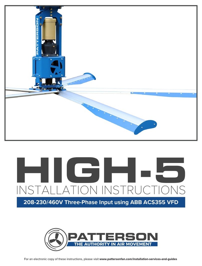
Patterson HIGH-5 User manual

HIGH-5
High Volume Ceiling Fan
Installation Manual
Blythewood, SC 29016 · 800.768.3985 · www.pattersonfan.com

Rev 3, Page 4
Addendum
To
High-5
Installation
Instructions
(Mechanical Only)
Please Note: This document is meant to be used in con unction with
the Installation Instruction drawings that accompany this unit.

Rev 3, Page 5
INCLUDED IN YOUR SHIPMENT
5 Fan Blades
1 Fan Assembly
1 Mounting Bracket
4 Turnbuckles ”
Bolts, nuts, washers, and clamps of various sizes (see High-5 Installation Instruction drawings
for types and quantities)
FAN SAFETY COMPONENTS PROVIDED
Assembly safety cable (1)
Guy wires (4)
Blade Safety plates (5)
Blade/Hub safety wire (1)
TOOLS TO GET STARTED
Scissor lift
Wrench and socket set (5/16” – ¾” needed)
” Nut driver
Torque wrench
Standard and Phillips screwdrivers
Level
Note: In order to protect personnel, equipment, and the fan, it is important that all of the
above safety components are installed per these instructions. Failure to properly install any or
all of these safeguards may void the manufacturer’s warranty.
FAN SPACING, PLACEMENT, AND CLEARANCE
Fans should be mounted such that the blades are a minimum of 10 feet above the floor. Also,
ensure that the fan blades have a clearance equal to 15% of the fan’s diameter in all directions.
Care should be taken when installing the fan around a fire sprinkler system. The VFD is
equipped with the ability to connect to the fire suppression system – emergency stopping the
fans in case of a fire. However, it is the responsibility of the installer to read and comply with
all local codes and regulations.
MAINTENANCE
Prior to performing any maintenance on the fan, it MUST be disconnected from the power
source by means of the lockable disconnect located on the VFD box.
Control Boxes – Clean inside of boxes occasionally, gently using a can of compressed air if
desired. Wipe down or dust the exterior of the boxes periodically

Rev 3, Page 6
Gearbox – Periodic maintenance will ensure your fan remains operational for its intended life.
While Patterson recommends that the end-user annually checks and changes the gearbox oil,
failure to do so will not void any warranties. Oil type used is Chevron® Delo Gear ESI 85W-140.
Contact Patterson at (800) 768-3985 for availability.
Hub Grease – Hub should be inspected yearly to ensure proper lubrication. Grease type is
Mobil Unirex EP2. Add grease as needed, filling slowly until grease passes through the upper
seal hole.
Mounting Hardware – All nuts and bolts related to mounting of the fan unit should be checked
for tightness annually. In addition, guy wires need to be inspected to ensure they remain taut
and show no signs of fraying.
Blades – Blades can be occasionally wiped down with a damp cloth. A mild detergent can also
be used if desired. Inspect safety devices yearly; ensure that safety plate bolts are tightened as
recommended and that safety cable remains in place.

Rev 3, Page 7
INSTALLATION PROCEDURES – KEY POINTS
Step 1: Install Mounting Hardware
-Reference: Page 11 and Page 16 of the High-5 Installation Instructions
A) It is important to attach the mounting hardware separately from the fan assembly.
B) Attach the mounting hardware as shown on page 11 of the Installation Instructions.
i) Refer to the diagram on page 11 to determine which set of bolt slots to
use on the mounting hardware. For I-beam width less than 7 ”, use slots
labeled “A”. I-beams wider than 7 ” should use slots labeled “B”.
ii) For I-beam thickness greater than ½”, use the provided spacer as shown
in Note 3, page 11.
iii) Be sure to tighten all nylon lock nuts to appropriate torque to prevent
them from vibrating loose during operation. Nuts can be used only once.
iv) If a downrod was ordered, attach one end of the rod to the swivel joint
on the mounting hardware using the downrod clamp (see page 11 of the
Installation Instructions).
Step 2: Attach Fan Assembly to Mounting Hardware
-Reference: Page 12, View A of the High-5 Installation Instructions
A) Using a scissor lift, raise the fan assembly until its mounting holes line up with the holes
on the swivel joint at the bottom of the mounting hardware (see page 12, view A). If a
downrod is used, attach the fan assembly to the holes provided on the end of the rod.
B) Important: Please note that the swivel joint (or downrod) must be located in between
the mounting holes on the fan assembly. Refer to page 12, View A.
C) Secure the fan assembly to the mounting hardware (or end of the downrod) as shown
on page 12 view A of the Installation Instructions.
Step 3: Install Fan Assembly Safety Cable
-Reference: Page 12, View A of the High-5 Installation Instructions
Note: This step is mandatory. Failure to install the safety cable may void the manufacturer’s
warranty.
A) Pass one end of the safety cable through the holes on the assembly’s vertical supports
(see page 12, view A).

Rev 3, Page 8
B) The opposite end of the safety cable should be passed over the top of the I-beam.
C) Connect the two ends of the cable together by means of 4 saddle clamps (provided) in
the manner shown on page 12, view A of the Installation Instructions. Tighten the
saddle clamps securely using a ½” socket.
Step 4: Install Guy Wires
-References: Page 12 and Page 17 of the High-5 Installation Instructions
Note: For maximum stability, the angle formed between the guy wire and the ceiling should be
less than 45 degrees.
This step is mandatory. Failure to install the guy wires may void the manufacturer’s
warranty. The following steps should be performed with the aid of a scissor lift.
A) Open the quick link located on the fan assembly. Slide one eye of the 1/4” turnbuckle
into the link. Close the quick link.
B) On the opposite eye of the turnbuckle, attach another quick link, followed by the looped
end of the guy wire. It should appear like the picture below. Also see: page 12, View B.
C) Pass the opposite end of the guy wire through the eye bolt of a beam clamp (not
supplied). Pull the wire as tight as possible, making sure the fan assembly remains in
the vertical position. Use 3 saddle clamps to crimp the end of the guy wire together in
the manner shown on page 12, view D of the Installation Instructions.

Rev 3, Page 9
D) Repeat steps A – C for the remaining three guy wires.
E) Once all guy wires are in place, use the turnbuckles to take out any remaining slack.
Periodically check the fan assembly with a level to ensure it remains in the vertical
position. Continue adjusting by means of the turnbuckles until all cables are
satisfactory. Guy wires should be taut, but not over stressed. Finally, recheck all saddle
clamps for tightness.
Step 5: Install Fan Blades
-Reference: Page 13 and Pages 18, 19, & 20 of the High-5 Installation Instructions
A) Care should be taken when installing the blades to ensure they are not bent or
damaged, as this may affect fan performance.
B) Insert the 5/8-11 x 3” blade bolt (with washer) through the fan hub and into the
corresponding hole in the blade (see page 13 of the Installation Instructions). Tighten
the bolt until it is partially snug, but do not secure it all the way.
C) Pitch the leading edge of the blade up. Insert the 5/16-18 NC x 1” bolt (with necessary
washers) through the fan hub and into the corresponding hole in the fan blade. Tighten
and secure this bolt to 15 lb-ft.
D) Tighten and secure the large blade bolt to 120 lb-ft.
E) Important: Be sure to remove the protective plastic film from the blade.
F) Install the blade bolt safety lock (part #203692) onto the threads of the large blade bolt
as shown on page 13 of the Installation Instructions. Note: These blade bolt safety
locks must be installed. Failure to do so may void the manufacturer’s warranty.
G) Repeat steps B – E for the remaining 4 blades.
Step 6: Install Blade Safety Plates
-Reference: Page 13 and Pages 18, 19, & 20 of the High-5 Installation Instructions
Note: This step is mandatory. Failure to install the blade safety plates may void the
manufacturer’s warranty.
A) Place one of the blade safety plates on top of the fan blade as shown on page 13 of the
Installation Instructions. Make sure the aluminum flat washer (part #202048) is placed
underneath the safety plate (see page 13).

Rev 3, Page 10
B) Using the bolts provided, along with the necessary washers, tighten and secure the
safety plate to the fan hub and blade as shown on page 13 of the Installation
Instructions.
C) Repeat steps A – B for the remaining 4 safety plates. Recheck all bolts for tightness.
Step 7: Install Blade Safety Cable
-Reference: Page 12, View C of the High-5 Installation Instructions
Note: This step is mandatory. Failure to install the blade safety cable may void the
manufacturer’s warranty.
A) Pass the safety cable alternately through the holes at the corners of the fan hub
pentagon and the holes of the blade pins (see page 12, view C).
B) Overlap the wire and clamp it together using 3 saddle clamps in the manner shown on
page 12, view C of the Installation Instructions.
Step 8: Remove Plug in Cap of Gearbox
-Reference: Note 4, Page 13 of the High-5 Installation Instructions
Note: This step is mandatory. Failure to remove the plug may cause gearbox seals to leak
due to pressurization of the lubrication fluid, possibly voiding the manufacturer’s warranty.
A) Remove plug in cap of the gearbox prior to operation of the fan (see page 13 of the
Installation Instructions).
This completes the mechanical installation of your
High-5 Fan.

1/2-13 NC GRADE 8 BOLTS SHOULD BE TIGHTENED TO 80 LB-FT
EXCEPT PRE-ASSEMBLED 1/2-13x4"LG (SWIVEL TUBE SHOULD MOVE FREELY)
7.
•EVALUATE BLADE CLEARANCE AND WHETHER A DOWN ROD IS REQUIRED.2. A. IF SO, INCLUDE A DOWN ROD (SEE LEFT VIEW)• B. IF NOT, BOLT THE DRIVE UNIT DIRECTLY TO THE INSTALLATION SUPPORT (SEE• VIEW A ON PAGE 12) USING THE 3/8-16 NC BOLTS PROVIDED.
202047 SPACER: FOR BEAM FLANGE THICKNESS OVER 1/2", MAKE SURE THAT AT3. LEAST 1/8" OF THREADS EXCEEDS OF NYLON LOCK NUT IF NOT, USE LONGER 1/2-13
GRADE 8 BOLTS (NOT INCLUDED) SEE VIEWS ABOVE
INSTALL THE DRIVE UNIT SAFETY CABLE (1X) (PAGE 12, VIEW A)4. INSTALL THE DRIVE UNIT GUY CABLES (4X). (PAGE 12, VIEW B)5. 3/8-16 NC BOLTS SHOULD BE TIGHTENED TO 25 LB-FT6.
WARNINGS:
-FOR INDUSTRIAL USE ONLY
-AN ELECTRIC DRIVE MUST BE USED TO CONNECT THE FAN (SOLD SEPARATELY)
THE DISTANCE "Y" BETWEEN BEAM AND PLATES SHOULD BE AS SMALL AS POSSIBLE
• FOR FLANGE WIDER THAN 9-3/4" CONTACT OUR ENGINEERING FOR APPROVAL
INSTALLATION NOTES:
BEFORE INSTALLING THE FAN, ENSURE THAT THE STRUCTURE WHERE IT WILL BE FIXED IS
SOLID ENOUGH TO SUPPORT THE LIVE LOAD OF IT (SEE SPECIFICATIONS SHEET).
SECURE THE PRE ASSEMBLED INSTALLATION SUPPORT TO THE H-BEAM USING THE1. FASTENERS PROVIDED:
FOR FLANGE WIDTH UP TO 7-1/4", USE SLOTS "A" (SEE VIEW ABOVE)• FOR FLANGE WIDTH FROM 7-1/4" TO 9-3/4" USE SLOTS "B" (SEE VIEW ABOVE)•
P/N DESCRIPTION QTY
202469 FAN HVLS INSTALLATION SUPPORT (PRE-ASSEMBLED) 1
201839 FAN HVLS INST SUPPORT TOP PLATE 2
202047 FAN HVLS INST SUPPORT BEAM SHIM 2
203809 HEX BOLT 1/2-13 NC X 2 1/4" LG Z/P GR 8 4
203408 WASHER 1/2 GR8 12
110667 NYLON INSERT LOCKNUT 1/2-13 Z/P GR 5 6
201837 FAN HVLS INST. SUPPORT SIDE BRACKET (OPTIONAL) 2
:
NUMBER
NUMÉRO
FAN HVLS SUPPORT INSTALLATION INSTRUCTIONS
P-24872
P.F. SAME AS REV 2
PAR / BY :
2013-04-11
3
DATE (Y/M/D) :
RÉVISION
REVISION
DWG P-24872
:
TITRE
TITLE
RÉVISION / REVISION DESCRIPTION
3
P/N 203623
PAGE 11
201839
(SEE NOTE 3) 203408
202469
SWIVEL TUBE
H-BEAM FROM BUILDING
110667
NOTE 7
202047
201837
DOWN ROD & SIDE SUPPORT
PLATES (OPTIONAL):
201838
203809
201836
A
B
VIEW - NOTE 1
FLANGE THICKNESS <1/2"
(SEE NOTE 3)
Y
FLANGE WIDTH
1/8" MIN
(SEE NOTE 3)
VIEWS - NOTE 3 >1/2"

NUMBER
NUMÉRO
:
P-24872
PAGE 12
FAN HVLS SAFETY CABLES INSTALLATION INSTRUCTIONS
3
DATE (Y/M/D) :
PAR / BY :
DESCRIPTIONRÉVISION / REVISION
TITLE
TITRE
:
P/N 203623
DWG P-24872
REVISION
RÉVISION
3
2013-04-11
SAME AS REV 2
P.F.
INSTALLATION OF THE BLADE SAFETY CABLE (#202163):
PASS THE WIRE ALTERNATELY THRU THE HOLES OF THE BLADE
MOUNTING PENTAGON AND THE HOLES OF THE BLADE PINS, OVERLAP
THE WIRE ROPE BY AT LEAST 4-3/4" AND PLACE 3 SADDLE CLIPS AS
ILLUSTRATED.
3/32" SADDLE CLIPS SHOULD BE TIGHTENED TO 4 LB-FT
WARNINGS:
-FOR INDUSTRIAL USE ONLY
-AN ELECTRIC DRIVE MUST BE USED TO CONNECT THE FAN (SOLD SEPARATELY)
P/N DESCRIPTION QTY
165710 CABLE 3/32'', 7X7, 13 FT LG 4
202163 CABLE 3/32'', 7X7, 8 FT LG 1
202164 CABLE 1/4", 7X19, 10 FT LG 1
171791 3/32 SADDLE CLIP ZINC PLATED 15
187108 1/4 SADDLE CLIP ZINC PLATED 4
149003 CABLE THIMBLE 3/32 (4x INSTALLED ON 165710) 8
202837 QUICK LINK 3/16" 8
201971 HEX BOLT 3/8-16 NC X 4 1/4" LG Z/P GR 5 2
203412 WASHER 3/8 GR 8 4
110665 NYLON INSERT LOCKNUT 3/8-16 Z/P GR 5 2
169735 1/4" EYE & EYE TURNBUCKLE 4
VIEW B
169735
202837
VIEW A
165710 (4x)
INSTALLATION OF THE FRAME SAFETY CABLE (#202164):
THE WIRE ROPE PASSES OVER THE H-BEAM AND THRU
THE HOLES IN THE VERTICAL TUBES.
SADDLE CLIPS #187108 SHOULD BE INSTALLED WITH
THE SADDLE ON THE "LIVE" OR LONG END OF THE ROPE
AND THE U-BOLT ON THE "DEAD" OR SHORT END OF
ROPE. POSITION THEM THE WAY ILLUSTRATED TO
ENSURE THE MAXIMUM STRENGTH.
1/4" WIRE ROPE CLIPS SHOULD BE TIGHTEN TO 15 LB-FT
IF A DOWN ROD IS INSTALLED, USE THE CABLE
PROVIDED WITH THE DOWN ROD
201971
203412
203412
110665
187108 (4x)
4 3/4" MIN
VIEW C
202163
171791 (3x)
171791 (3x)
149003
INSTALLATION OF THE 4 GUY CABLES (#165710):
SADDLE CLIPS #171791 SHOULD BE INSTALLED WITH THE SADDLE ON THE LIVE OR LONG
END OF THE CABLE AND THE U-BOLT ON THE DEAD OR SHORT END OF THE CABLE.
3/32" SADDLE CLIPS SHOULD BE TIGHTENE TO 4 LB-FT
TIGHTEN THE CABLES UNTIL FRAME IS LEVELED
DO NOT OVER STRESS THE CABLE
IF 5 FT OR 10 FT DOWN ROD IS INSTALLED, USE LONGER GUY CABLES #203994 PROVIDED
WHEN FAN IS LEVELED, ANGLE BETWEEN ROOF AND GUY CABLES MUST NOT EXCEED 45º
VIEW D
3 1/4" MIN
OVERALL DIMENSIONS
48 "
(WITHOUT DOWN ROD)
24 FT WHEN #201259 BLADE SET IS INSTALLED
20 FT WHEN #202359 BLADE SET IS INSTALLED
18 FT WHEN #202360 BLADE SET IS INSTALLED
30-45

INSTALLATION NOTES:
INSTALL THE BLADE ASSY, BOLTS AND SAFETY LOCK (SEE SECTION VIEW)1. ADD THE SAFETY PLATES2. FIT THE BLADE SAFETY CABLE (SEE VIEW C ON PAGE 12).3. REMOVE PLUG IN CAP OF GEARBOX BEFORE USE4. BLADE SAFETY LOCK MUST ALWAYS BE IN PLACE WHEN FAN IS OPERATING SEE SECTION5. VIEW FOR INSTALLATION DETAIL. IF LOST OR BROKEN, CAN BE REPLACED BY MCMASTER
CARR # 98407A138
REMOVE PLASTIC FILM ON BLADES AFTER INSTALLATION6. 2 HP FAN POWER UNIT KIT #203194 MATCH WITH 24' FAN BLADE SET #2012597. 1 HP FAN POWER UNIT KIT #203530 MATCH WITH 18' FAN BLADE SET #202360 OR 20' FAN8. BLADE SET #202359
5/8-11 BOLT SHOULD BE TIGHTENED TO 120 LB-FT9. 5/16-18 BOLTS SHOULD BE TIGHTENED TO 15 LB-FT10.
SECTION VIEW
202674
203584
203410
NOTE 10
WARNINGS:
-FOR INDUSTRIAL USE ONLY
-AN ELECTRIC DRIVE MUST BE USED TO CONNECT THE FAN (SOLD SEPARATELY)
PART
NUMBER DESCRIPTION QTY
201895
202361
202294
FAN HVLS 24' BLADE ASSY (SET #201259)
FAN HVLS 20' BLADE ASSY (SET #202359)
FAN HVLS 18' BLADE ASSY (SET #202360) 5
201988 FAN HVLS 5/8-11X3:1/2'' BLADE BOLT 5
200153 BELLEVILLE SPRING LOCK WASHER 5/8" 5
203135 HEX BOLT 5/16-18 NC X 1" LG Z/P GR 5 10
201972 HEX BOLT 5/16-18 NC X3/4" LG Z/P GR 5
(BOLTED ON 203193) 10
202674 HEX BOLT 5/16-18 NC X 1/2" LG Z/P GR5 5
203584 LOCK WASHER 5/16 HEAT TREATED 25
203410 WASHER 5/16 GR 8 25
202048 FLAT WASHER 5/16 (ALUMINIUM) 5
201864 FAN HVLS BLADE SAFETY PLATE 5
203692 FAN HVLS 5/8-11 BOLT SAFETY LOCK 5
NUMBER
NUMÉRO
:
P-24872
PAGE 13
FAN HVLS BLADES INSTALLATION INSTRUCTIONS
3
DATE (Y/M/D) :
PAR / BY :
DESCRIPTIONRÉVISION / REVISION
TITLE
TITRE
:
P/N 203623
DWG P-24872
REVISION
RÉVISION
3
2013-04-11
SAME AS REV 2
P.F.
10°REF
203692
NOTE 3
PASS THRU THIS HOLE TO
INSTALL 203692 IN 5/8-11 BOLT SLOT
203135
IF DRAINING HOLES NEED TO BE PLUGGED,
USE MCMASTER-CARR PLUG #
201864
203584
203135
2598K21,9191T31 OR 9545K51
NOTE 10
203410
NOTE 10
(2x)
NOTE 10
203410NOTE 9
201988 203584
THE BOLT HEAD
202048
CONVEX SIDE MUST BE AGAINST
(FRAME ASSY FROM SET #203194)
203193
NOTE 5
NOTE 4
203692 (BLADE BOLT SAFETY LOCK)
200153
201972
203584
203410
BLADE
201895,
202361 OR
202294

NUMBER
NUMÉRO
:
P-24872
PAGE 14
FAN HVLS PU 2HP (203193) PARTS LIST
3
DATE (Y/M/D) :
PAR / BY :
DESCRIPTIONRÉVISION / REVISION
TITLE
TITRE
:
P/N 203623
DWG P-24872
REVISION
RÉVISION
3
2013-04-11
LOVEJOY COUPLING REPLACED BY CHAIN COUPLING, NEW
PART NUMBERS (202492, 204519 & 204520), KEY #203523
REPLACED BY A SECOND KEY #110104, NOTE ADDED
P.F.
MAINTENANCE INFORMATION:
-GEAR BOX OIL: CHEVRON DELO GEAR ESI 85W-140
-FILL TO OIL LEVEL PORT
-
PATTERSON RECOMMENDS CHECKING AND CHANGING OIL ANNUALLY.
HOWEVER, FAILURE TO DO SO DOES NOT VOID THE WARRANTY.
-HUB GREASE: MOBIL UNIREX EP2
-FILL SLOWLY UNTIL GREASE PASSES THROUGH UPPER SEAL HOLE
-BOLTS & NUTS TIGHTENING MUST BE INSPECT ANNUALLY,
IF REMOVED, USE APPROPRIATE TORQUE:
-5/16-18 BOLTS RECOMMENDED TORQUE: 15 LB-FT
-3/8-16 BOLTS RECOMMENDED TORQUE : 25 LB-FT
-1/2-13 BOLTS RECOMMENDED TORQUE : 60 LB-FT
-9/16-18 BOLTS RECOMMENDED TORQUE: 90 LB-FT
-1/2-13 SET SCREWS IN COUPLING RECOMMENDED TORQUE: 50 LB-FT
(OIL LEVEL)
(DRAIN HOLE)
FAN HVLS PU 2HP (203193) PARTS LIST FOR S/N PU13010058 & UP
3
3
3
3
3
32 29
ITEM
NO. PART
NUMBER DESCRIPTION QTY
1 201874 FAN HVLS MAIN FRAME TOP CROSSMEMBER 1
2 204519 FAN HVLS MAIN FRAME TUBE (SOLD IN PAIR) 2
3 201881 FAN HVLS MAIN FRAME HUB SUPPORT PLATE 1
4 201882 FAN HVLS MAIN FRAME HUB SUPPORT SIDE PLATE 2
5 201880 FAN HVLS MAIN FRAME SAFETY PLATE 2
6 202492 FAN HVLS MAIN FRAME GEARBOX SUPPORT PLATE 1
7 160215 EM-AC-2HP18F56C-230/460/3/60-TEFC - 2HP MOTOR 1
8 202503 RH-565-36:1-1:3/8-56C-C-PF-VB - GEARBOX 1
9 204520 FAN HVLS MAIN FRAME AXLE K1/4 1
10 204673 2-2.716-.375(TB)-W/HOLE - UPPER SHAFT SEAL 2
11 201713 2.375-3.543-.375(TA) - BOTTOM SHAFT SEAL 1
12 154936
154931 LM48548 - FAN HVLS UPPER HUB BEARING
LM48510 - FAN HVLS UPPER HUB BEARING CUP 1
13 163017
163016 25580 - FAN HVLS BOTTOM HUB BEARING
25520 - FAN HVLS BOTTOM HUB BEARING CUP 1
14 195376 FAN HVLS MAIN FRAME HUB H-618 (GREASE FITTING &
BEARING CUPS INSTALLED) 1
15 143975 5016H1:5/8K3/8-2S3/8-24-W/S - UPPER CHAIN COUPLING 1
16 178992 5016H1:1/4K1/4-2S5/16-18-W/S - BOT. CHAIN COUPLING 1
17 104733 5016(INCL. 1 C/L) - CHAIN FOR COUPLING 1
18 145482 5016(WITH TWO SEALS) - COVER 1
19 110104 1/4" SQUARE KEY X 1:1/2" LG 2
20 203207 FAN HVLS 1:3/8-12 SLOTTED NUT - MODIFIED 1
21 201896 FAN HVLS BLADE HUB WELDMENT 1
22 201972 HEX BOLT 5/16-18 NC X 3/4" LG Z/P GR 5 10
23 203135 HEX BOLT 5/16-18 NC X 1" LG Z/P GR 5 4
24 200572 HEX BOLT 5/16-18 X 1-1/4" Z/P GR 5 1
25 203651 HEX BOLT 5/16-18 NC X 4:1/4" LG Z/P GR 5 12
26 155684 HEX BOLT 3/8-16 X 1" LG Z/P GR 5 4
27 201970 HEX BOLT 1/2-13 NC X 1 3/4" LG Z/P GR 5 4
28 203167 HEX BOLT 9/16-18 X 1-1/2" Z/P GR 5 6
29 183038 NYLON INSERT LOCKNUT 5/16-18 Z/P GR 5 16
30 110667 NYLON INSERT LOCKNUT 1/2-13 Z/P GR 5 4
31 202604 HEX JAM NUT 5/16-18 Z/P GR2 1
32 203410 WASHER 5/16 GR 8 (11/32X11/16X.05-.08) 42
33 203408 WASHER 1/2 GR8 (17/32 X 1:1/16 X .09-.18) 8
34 203409 WASHER 9/16 GR8 ( 19/32X1:5/32 X .09-.13) 6
35 203584 LOCK WASHER 5/16 HEAT TREATED 10
36 203583 LOCK WASHER 3/8 HEAT TREATED 4
37 203581 LOCK WASHER 9/16 HEAT TREATED 6
38 203221 COTTER PIN Ø1/8" X2:1/2" LG 1
39 202844 PLUG M(NPT1/4-18)-MAGNETIC-ACIER-SOCKET HEAD 1
40 203700 PLUG M(NPTF1/4-18)-MAGNETIC-ACIER-SQ.HEAD 1
41 203622 FAN HVLS MAINTENANCE STICKER 1
42 204287 STICKER FOR FAN HVLS DRIVE 2HP #203194 1
FLANGE WHEN AXLE IS REMOVED AND
REPLACED TO AVOID GREASE LEAK
7
125
4
3
5
2
26
12
21
9
10
11
13
14
20
38
23
27
29
30
28
32
32
32
36
33
33
3437
35
8
32
41
(OPPOSITE SIDE)
42
18
15
17
16
6
22
19
USE OIL RESISTANT SILICONE ON THIS 3
24
21
31
40
39
FILLING HOLE & BREATHER
(REMOVE PLUG IN CAP
BEFORE USE)

32
33
32
(DRAIN HOLE)
(OIL LEVEL)
32
3
3
3
3
3
37
32 29
MAINTENANCE INFORMATION:
-GEAR BOX OIL: CHEVRON DELO GEAR ESI 85W-140
-FILL TO OIL LEVEL PORT
-
PATTERSON RECOMMENDS CHECKING AND CHANGING OIL ANNUALLY.
HOWEVER, FAILURE TO DO SO DOES NOT VOID THE WARRANTY.
-HUB GREASE: MOBIL UNIREX EP2
-FILL SLOWLY UNTIL GREASE PASSES THROUGH UPPER SEAL HOLE
-BOLTS & NUTS TIGHTENING MUST BE INSPECT ANNUALLY,
IF REMOVED, USE APPROPRIATE TORQUE:
-5/16-18 BOLTS RECOMMENDED TORQUE: 15 LB-FT
-3/8-16 BOLTS RECOMMENDED TORQUE : 25 LB-FT
-1/2-13 BOLTS RECOMMENDED TORQUE : 60 LB-FT
-9/16-18 BOLTS RECOMMENDED TORQUE: 90 LB-FT
-1/2-13 SET SCREWS IN COUPLING RECOMMENDED TORQUE: 50 LB-FT
ITEM
NO. PART
NUMBER DESCRIPTION QTY
1 201874 FAN HVLS MAIN FRAME TOP CROSSMEMBER 1
2 204519 FAN HVLS MAIN FRAME TUBE (SOLD IN PAIR) 2
3 201881 FAN HVLS MAIN FRAME HUB SUPPORT PLATE 1
4 201882 FAN HVLS MAIN FRAME HUB SUPPORT SIDE PLATE 2
5 201880 FAN HVLS MAIN FRAME SAFETY PLATE 2
6 202492 FAN HVLS MAIN FRAME GEARBOX SUPPORT PLATE 1
7 201573 EM-AC-1HP18F56C-208-230/460/3/60-TEFC - 1 HP MOTOR 1
8 202503 RH-565-36:1-1:3/8-56C-C-PF-VB - GEARBOX 1
9 204520 FAN HVLS MAIN FRAME AXLE K1/4 1
10 204673 2-2.716-.375(TB)-W/HOLE - UPPER SHAFT SEAL 1
11 201713 2.375-3.543-.375(TA) - BOTTOM SHAFT SEAL 1
12 154936
154931 LM48548 - FAN HVLS UPPER HUB BEARING
LM48510 - FAN HVLS UPPER HUB BEARING CUP 1
13 163017
163016 25580 - FAN HVLS BOTTOM HUB BEARING
25520 - FAN HVLS BOTTOM HUB BEARING CUP 1
14 195376 FAN HVLS MAIN FRAME HUB H-618 (GREASE FITTING &
BEARING CUPS INSTALLED) 1
15 143975 5016H1:5/8K3/8-2S3/8-24-W/S - UPPER CHAIN COUPLING 1
16 178992 FAN HVLS BLADE SUPPORT STIFFENER 1
17 104733 5016(INCL. 1 C/L) - CHAIN FOR COUPLING 1
18 145482 5016(WITH TWO SEALS) - COVER 1
19 110104 1/4" SQUARE KEY X 1:1/2" LG 2
20 203207 FAN HVLS 1:3/8-12 SLOTTED NUT - MODIFIED 1
21 201896 FAN HVLS BLADES HUB WELDMENT 1
22 201972 HEX BOLT 5/16-18 NC X 3/4" LG Z/P GR 5 10
23 203135 HEX BOLT 5/16-18 NC X 1" LG Z/P GR 5 4
24 200572 HEX BOLT 5/16-18 X 1-1/4" Z/P GR 5 1
25 203651 HEX BOLT 5/16-18 NC X 4:1/4" LG Z/P GR 5 12
26 155684 HEX BOLT 3/8-16 X 1" LG Z/P GR 5 4
27 201970 HEX BOLT 1/2-13 NC X 1 3/4" LG Z/P GR 5 4
28 203167 HEX BOLT 9/16-18 X 1-1/2" Z/P GR 5 6
29 183038 NYLON INSERT LOCKNUT 5/16-18 Z/P GR 5 16
30 110667 NYLON INSERT LOCKNUT 1/2-13 Z/P GR 5 4
31 202604 HEX JAM NUT 5/16-18 Z/P GR2 1
32 203410 WASHER 5/16 GR 8 (11/32X11/16X.05-.08) 42
33 203408 WASHER 1/2 GR8 (17/32 X 1:1/16 X .09-.18) 8
34 203409 WASHER 9/16 GR8 ( 19/32X1:5/32 X .09-.13) 6
35 203584 LOCK WASHER 5/16 HEAT TREATED 10
36 203583 LOCK WASHER 3/8 HEAT TREATED 4
37 203581 LOCK WASHER 9/16 HEAT TREATED 6
38 203221 COTTER PIN Ø1/8" X2:1/2" LG 1
39 202844 PLUG M(NPT1/4-19)-MAGNETIC-ACIER-SOCKET HEAD 1
40 203700 PLUG M(NPTF1/4-18)-MAGNETIC-ACIER-SQ.HEAD 1
41 203622 FAN HVLS MAINTENANCE STICKER 1
42 204288 STICKER FOR FAN HVLS DRIVE 1HP #203530 1
NUMBER
NUMÉRO
:
P-24872
PAGE 15
FAN HVLS PU 1HP (203531) PARTS LIST
3
DATE (Y/M/D) :
PAR / BY :
DESCRIPTIONRÉVISION / REVISION
TITLE
TITRE
:
P/N 203623
DWG P-24872
REVISION
RÉVISION
3
2013-04-11
GEARBOX #202426 REPLACED BY #202503, NEW PART
NUMBERS (202492, 204519 & 204520), KEY #203523
REPLACED BY A SECOND KEY #110104, NOTE ADDED
P.F.
FLANGE WHEN AXLE IS REMOVED AND
REPLACED TO AVOID GREASE LEAK
12
13
2
4
7
8
9
3
10
20
38
11
14
15
17
16
34
18
21
22
23
25
26
35
FAN HVLS PU 1HP (203531) PARTS LIST FOR S/N PU13010058 & UP
27
(OPPOSITE SIDE)
32
41 42
30
1
5
6
33
29
36
28
19
USE OIL RESISTANT SILICONE ON THIS 3
40
39
FILLING HOLE & BREATHER
(REMOVE PLUG IN CAP
BEFORE USE)
24
21
31

NUMBER
NUMÉRO
:
P-24872
PAGE 16
FAN HVLS INST. SUPPORT (202469) PARTS LIST
3
DATE (Y/M/D) :
PAR / BY :
DESCRIPTIONRÉVISION / REVISION
TITLE
TITRE
:
P/N 203623
DWG P-24872
REVISION
RÉVISION
3
2013-04-11
P/N 201837, 201971, 110665 & 203412
REMOVED
P.F.
MAINTENANCE INFORMATION:
-BUSHING WEAR
CHECK EVERY 3 MONTHS, REPLACE IF NECESSARY
-1/2-13 NC GRADE 8 BOLTS SHOULD BE TIGHTENED TO 80 LB-FT
EXCEPT PRE-ASSEMBLED 1/2-13x4"LG (SWIVEL TUBE SHOULD MOVE FREELY)
ITEM NO PART
NUMBER DESCRIPTION QTY
1 201845 FAN HVLS INST SUPPORT WELDMENT 1
2 201836 FAN HVLS INST SUPPORT TUBE ON CROSS MEMBER 1
3 202047 FAN HVLS INST SUPPORT BEAM SHIM 2
4 201839 FAN HVLS INST SUPPORT TOP PLATE 2
5 201838 FAN HVLS INST SUPPORT SWIVEL TUBE WELDMENT 1
6 148080 OILITE FLANGED BUSHING 4
7 203809 HEX BOLT 1/2-13 NC X 2 1/4" LG Z/P GR 8 4
8 203729 HEX BOLT 1/2-13 GRADE 8 W/HOLE 2
9 110667 NYLON INSERT LOCKNUT 1/2-13 Z/P GR 5 6
10 203408 WASHER 1/2 GR8 (17/32 X 1:1/16 X .09-.18) 12
11 203550 TAB WASHER M12 (SPAE NAUR #657-124) 2
12 110800 COTTER PIN Ø3/32" X1" LG 2
12
1
5
2
4
6
7
8
9
10
11
3

ITEM NO. PART NUMBER DESCRIPTION QTY
1 202164 CABLE 1/4", 7X19, 10 FT LG 1
2 202163 CABLE 3/32'', 7X7, 8 FT LG 1
3 165710 CABLE 3/32'', 7X7, 13 FT LG 4
4 149003 CABLE THIMBLE 3/32 8
5 202837 QUICK LINK 3/16" 8
6 171791 3/32 SADDLE CLIP ZINC PLATED 15
7 187108 1/4 SADDLE CLIP ZINC PLATED 4
8 201971 HEX BOLT 3/8-16 NC X 4 1/4" LG Z/P GR 5 2
9 203412 WASHER 3/8 GR 8 (13/32X13/16X.05-.08) 4
10 110665 NYLON INSERT LOCKNUT 3/8-16 Z/P GR 5 2
11 169735 1/4" EYE & EYE TURNBUCKLE 4
NUMBER
NUMÉRO
:
P-24872
PAGE 17
FAN HVLS INST. SUP. HARDWARE (201258) PARTS LIST
3
DATE (Y/M/D) :
PAR / BY :
DESCRIPTIONRÉVISION / REVISION
TITLE
TITRE
:
P/N 203623
DWG P-24872
REVISION
RÉVISION
3
2013-04-11
SAME AS REV 2
P.F.
11
3
7
8
10
1
5
4
6
6
9 2
4

NUMBER
NUMÉRO
:
P-24872
PAGE 18
FAN HVLS BLADE 24' DIA. (201895) PARTS LIST
3
DATE (Y/M/D) :
PAR / BY :
DESCRIPTIONRÉVISION / REVISION
TITLE
TITRE
:
P/N 203623
DWG P-24872
REVISION
RÉVISION
3
2013-04-11
REPLACEMENT KIT P/N ADDED
P.F.
MAINTENANCE INFORMATIONS:
-5/16-18 BOLTS RECOMMENDED TORQUE: 15 LB-FT
-203692 SAFETY LOCK MUST BE IN PLACE BEFORE OPERATING FAN
CAN BE REPLACED BY MCMASTER CARR #98407A138
NOTES:
24' BLADE SET #201259 TO BE MATCHED WITH 2HP POWER UNIT KIT #2031941. FOR (1x) BLADE 24' DIA. REPLACEMENT KIT INCLUDING REQUIRED
2. HARDWARE ORDER P/N 204812.
WHEN INSTALLING A REPLACEMENT
BLADE, USE ALL OF THE NEW PARTS ONLY, DISCARD ALL OLD
FASTENERS FOR SAFETY PURPOSE.
3
ITEM NO. PART
NUMBER DESCRIPTION QTY
1 201895 FAN HVLS BLADE 24' ASSY (WITH WINGLET) 1
2 201863 FAN HVLS BLADE SHAFT SUPPORT 1
3 201965 FAN HVLS BLADE WINGLET (SPARE PART) 1
4 201864 FAN HVLS BLADE SAFETY PLATE 1
5 201988 FAN HVLS 5/8-11X3:1/2'' BLADE BOLT 1
6 200153 BELLEVILLE SPRING LOCK WASHER 5/8" 1
7 202674 HEX BOLT 5/16-18 NC X 1/2" LG Z/P GR5 1
8 201972 HEX BOLT 5/16-18 NC X 3/4" LG Z/P GR 5
(SUPPLIED WITH 203193, PAGE 14) 2
9 203135 HEX BOLT 5/16-18 NC X 1" LG Z/P GR 5 2
10 203584 LOCK WASHER 5/16 HEAT TREATED
(2x SUPPLIED WITH 203193, PAGE 14) 5
11 203410 WASHER 5/16 GR 8 (11/32X11/16X.05-.08)
(2x SUPPLIED WITH 203193, PAGE 14) 5
12 202048 FLAT WASHER 5/16 (ALUMINIUM) 1
13 111123 EXT. RET. RING 1-1/2" 1
14 203692 FAN HVLS 5/8-11 BOLT SAFETY LOCK 1
4
2
56
7
10
12
13
8
9
11
9
14
1
3

NOTES:
20' BLADE SET #202359 TO BE MATCHED WITH 1HP POWER UNIT KIT #2035301. FOR (1x) BLADE 20' DIA. REPLACEMENT KIT INCLUDING REQUIRED2. HARDWARE ORDER P/N 204813.
WHEN INSTALLING A REPLACEMENT
BLADE, USE ALL OF THE NEW PARTS ONLY, DISCARD ALL OLD
FASTENERS FOR SAFETY PURPOSE
.
MAINTENANCE INFORMATIONS:
-5/16-18 BOLTS RECOMMENDED TORQUE: 15 LB-FT
-203692 SAFETY LOCK MUST BE IN PLACE BEFORE OPERATING FAN
CAN BE REPLACED BY MCMASTER CARR #98407A138
3
ITEM NO. PART NUMBER DESCRIPTION QTY
1 202361 FAN HVLS BLADE 20' ASSY (WITH WINGLET) 1
2 201863 FAN HVLS BLADE SHAFT SUPPORT 1
3 201965 FAN HVLS BLADE WINGLET 1
4 201864 FAN HVLS BLADE SAFETY PLATE 1
5 201988 FAN HVLS 5/8-11X3:1/2'' BLADE BOLT 1
6 200153 BELLEVILLE SPRING LOCK WASHER 5/8" 1
7 202674 HEX BOLT 5/16-18 NC X 1/2" LG Z/P GR5 1
8 201972 HEX BOLT 5/16-18 NC X 3/4" LG Z/P GR 5
(SUPPLIED WITH 203531, PAGE 15) 2
9 203135 HEX BOLT 5/16-18 NC X 1" LG Z/P GR 5 2
10 203584 LOCK WASHER 5/16 HEAT TREATED
(2x SUPPLIED WITH 203531, PAGE 15) 5
11 203410 WASHER 5/16 GR 8 (11/32X11/16X.05-.08)
(2x SUPPLIED WITH 203531, PAGE 15) 5
12 202048 FLAT WASHER 5/16 (ALUMINIUM) 1
13 111123 EXT. RET. RING 1-1/2" 1
14 203692 FAN HVLS 5/8-11 BOLT SAFETY LOCK 1
NUMBER
NUMÉRO
:
P-24872
P.F. REPLACEMENT KIT P/N ADDED
2013-04-11
3
RÉVISION
REVISION
P/N 203623
DWG P-24872
:
TITRE
TITLE
RÉVISION / REVISION DESCRIPTION
PAR / BY :
DATE (Y/M/D) :
3
FAN HVLS BLADE 20' DIA. (202361) PARTS LIST
PAGE 19
13
2
4
5
6
78
10
11
9
12
14
1
3

NUMBER
NUMÉRO
:
P-24872
P.F. REPLACEMENT KIT P/N ADDED
2013-04-11
3
RÉVISION
REVISION
P/N 203623
DWG P-24872
:
TITRE
TITLE
RÉVISION / REVISION DESCRIPTION
PAR / BY :
DATE (Y/M/D) :
3
FAN HVLS BLADE 18' DIA. (202294) PARTS LIST
PAGE 20
MAINTENANCE INFORMATIONS:
-5/16-18 BOLTS RECOMMENDED TORQUE: 15 LB-FT
-203692 SAFETY LOCK MUST BE IN PLACE BEFORE OPERATING FAN
CAN BE REPLACED BY MCMASTER CARR #98407A138
NOTES:
18' BLADE SET #202360 TO BE MATCHED WITH 1HP POWER UNIT KIT #2035301. FOR (1x) BLADE 18'' DIA. REPLACEMENT KIT INCLUDING REQUIRED HARDWARE
2. ORDER P/N 204814.
WHEN INSTALLING A REPLACEMENT BLADE, USE
ALL OF THE NEW PARTS ONLY, DISCARD ALL OLD FASTENERS FOR
SAFETY PURPOSE.
3
ITEM NO. PART NUMBER DESCRIPTION QTY
1 202294 FAN HVLS BLADE 18' ASSY (WITH WINGLET) 1
2 201863 FAN HVLS BLADE SHAFT SUPPORT 1
3 201965 FAN HVLS BLADE WINGLET (SPARE PART) 1
4 201864 FAN HVLS BLADE SAFETY PLATE 1
5 201988 FAN HVLS 5/8-11X3:1/2'' BLADE BOLT 1
6 200153 BELLEVILLE SPRING LOCK WASHER 5/8" 1
7 202674 HEX BOLT 5/16-18 NC X 1/2" LG Z/P GR5 1
8 201972 HEX BOLT 5/16-18 NC X 3/4" LG Z/P GR 5
(SUPPLIED WITH 203531, PAGE 15) 2
9 203135 HEX BOLT 5/16-18 NC X 1" LG Z/P GR 5 2
10 203584 LOCK WASHER 5/16 HEAT TREATED
(2x SUPPLIED WITH 203531, PAGE 15) 5
11 203410 WASHER 5/16 GR 8 (11/32X11/16X.05-.08)
(2x SUPPLIED WITH 203531, PAGE 15) 5
12 202048 FLAT WASHER 5/16 (ALUMINIUM) 1
13 111123 EXT. RET. RING 1-1/2" 1
14 203692 FAN HVLS 5/8-11 BOLT SAFETY LOCK 1
13
2
4
5
6
7
8
9
10
11 12
14
1
3
Other manuals for HIGH-5
1
Table of contents
Other Patterson Fan manuals
Popular Fan manuals by other brands

NuTone
NuTone 765HFL instructions

Jocel
Jocel JVM030580 instruction manual

Westinghouse
Westinghouse Crescent Cove owner's manual

Middle Atlantic Products
Middle Atlantic Products DWR Series instruction sheet

Sygonix
Sygonix FE-50A operating instructions

BLAUBERG Ventilatoren
BLAUBERG Ventilatoren Centro-MZ 100 user manual