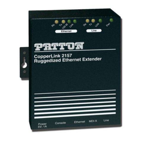
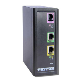
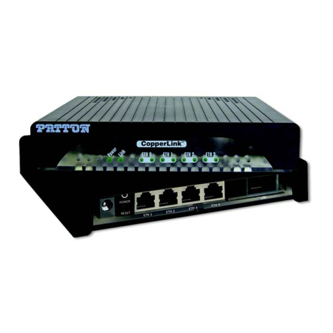
Patton CopperLink 1101E/IP67 User manual
Other Patton Extender manuals
Patton
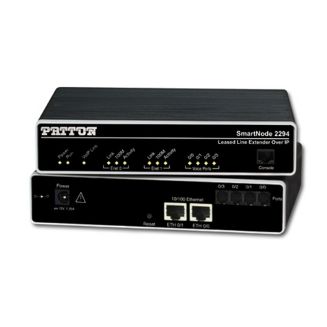
Patton SmartNode 2290 Series User manual
Patton
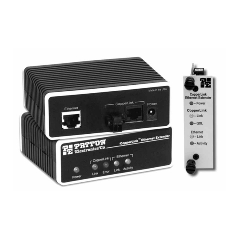
Patton 1053AS User manual
Patton
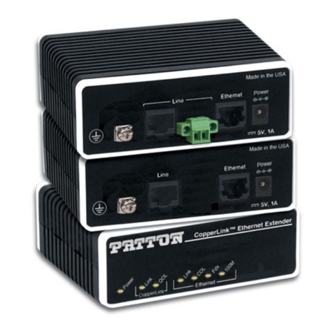
Patton 2168 User manual
Patton
Patton CopperLink E2168A User manual
Patton
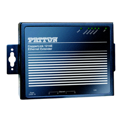
Patton CopperLink 1214E User manual

Patton
Patton copperlink 1101 User manual
Patton
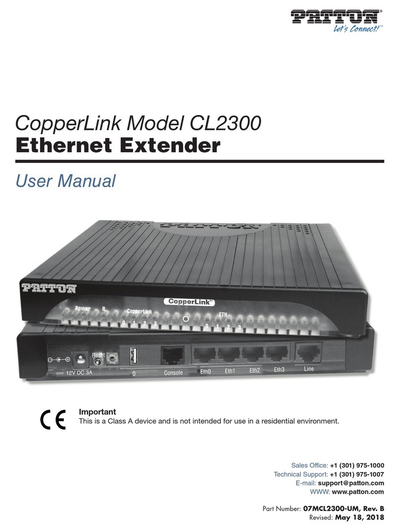
Patton CopperLink CL2300 User manual
Patton
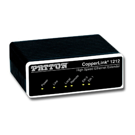
Patton CopperLink 1211 User manual

Patton
Patton 1052AS User manual
Patton
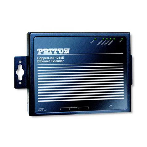
Patton CopperLink 1214E User manual
Patton
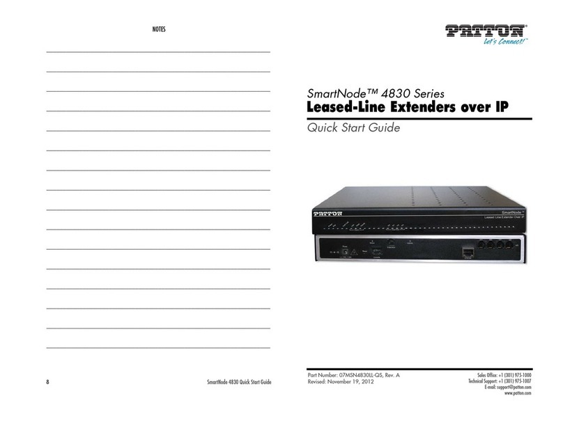
Patton SmartNode 4830 Series User manual

Patton
Patton 2158 User manual

Patton
Patton CopperLink 1101E User manual
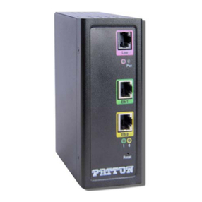
Patton
Patton CopperLink 1314R User manual

Patton
Patton SmartNode 2290 Series User manual
Patton
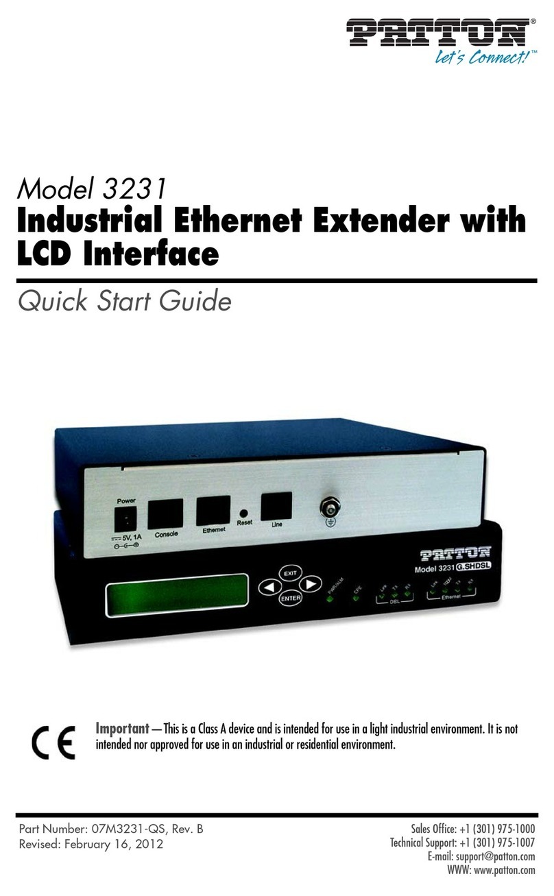
Patton 3231 User manual
Patton
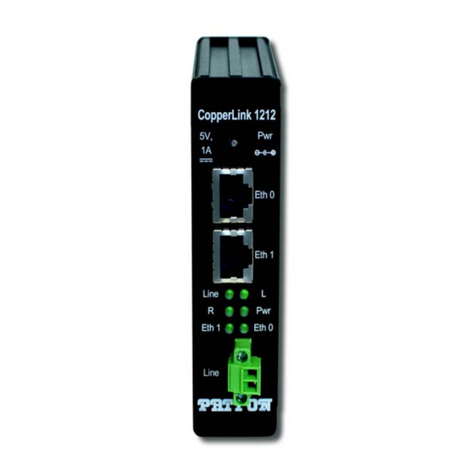
Patton CopperLink CL1211E User manual
Patton
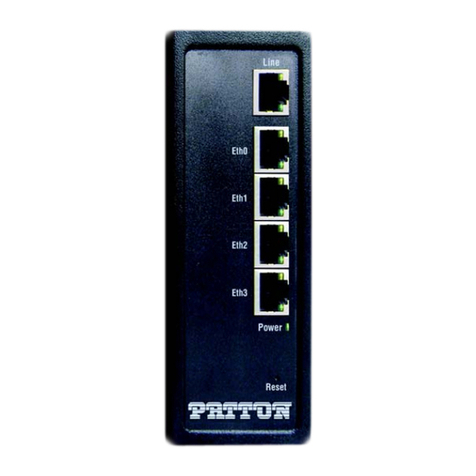
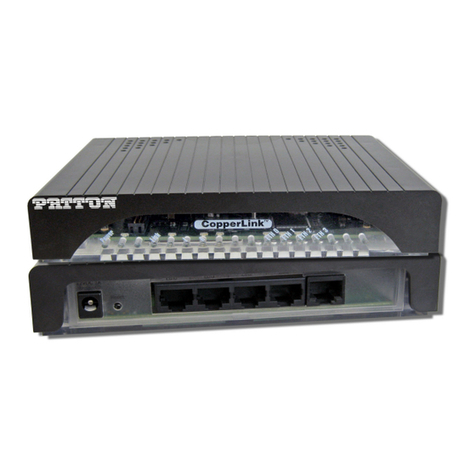
Patton CopperLink CL1300 User manual
Patton
Patton CopperLink 1214 User manual
Patton
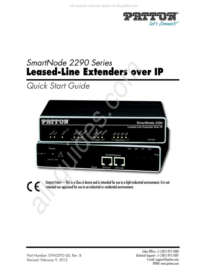
Patton SmartNode 2290 Series User manual
Popular Extender manuals by other brands

foxunhd
foxunhd SX-AEX01 operating instructions

TERK Technologies
TERK Technologies LFIRX2 owner's manual

Devolo
Devolo Audio Extender supplementary guide

Edimax
Edimax EW-7438RPn V2 instructions

Shinybow USA
Shinybow USA SB-6335T5 instruction manual

SECO-LARM
SECO-LARM ENFORCER EVT-PB1-V1TGQ installation manual
