PAU 100cc Extra 300-SP ARF User manual

1
100cc Extra 300-SP ARF
Instruction Manual
Congratulations and thank you for purchasing the Performance Aircraft Unlimited 105” Extra 300SP. The Extra
is arguably one of the most renowned aerobatic aircraft ever produced. Walter Extra who designed the original
Extra, named his aircraft by the horsepower rating of the motor placed in them. The Extra 300SP is one of the
newest releases in full scale, and now in R/C version.
Our aircraft was designed with 1,922sq inches of wing area while keep the total weight to a minimum. Whether
you want an aircraft precise enough to compete in IMAC or 3D until you’re airsick, the PAU Extra fits the bill.
Its light weight gives you the stability in high-alpha to take it to the extremes of the flight envelope. If tumbling

2
maneuvers are your thing, our Extra 300sp will deliver with picture perfect waterfalls and blistering tip spins
that are not for the faint of heart.
We believe you will find this to be one of the finest flying aircraft on the market. Most modelers will find the
assembly of this aircraft simple and straight forward. We recommend the builder follow the step-by-step
instructions to achieve the best performance and to ensure nothing was overlooked. This manual also includes
tip sections throughout that may help you in key areas during assembly. Please familiarize yourself with this
manual before assembly.
This manual is broken down into ten chapters for simplicity:
Chapter 1 - Parts Inventory
Chapter 2 - Preparation for Assembly
Chapter 3 - Landing Gear and Tail Wheel Assemblies
Chapter 4 - Canopy and Fuselage Hatch
Chapter 5 - Engine Installation
Chapter 6 - Cowling installation
Chapter 7 - Rudder Installation
Chapter 8 - Hardware Installation
Chapter 9 - Radio and Control Surface Setup
Chapter 10 - Final Inspection and Pre-Flight
Additional items needed to complete this aircraft, which are not included:
An engine, within the recommend range, and propeller: 80cc to 120cc
8 channel computer radio and receiver recommended
Batteries and switches (with regulators if using LiIon batteries)
Four aileron servos rated at least at 150oz of torque each
Two elevator servos rated at least at 200oz of torque each!
One or two rudder servo rated at least at 400oz of total torque
One throttle servo with push rod and links
Optional choke servo with push rod and links
One fueling dot or fueling device
3 to 4 feet of fuel tubing
Foam rubber
4-½ inch spinner
30 to 45 minute epoxy
A bottle of thin CA
Covering iron
Various modeling tools for assembly
½ inch low tack masking tape
3
Chapter 1
Parts inventory
Place an “” to ensure your kit is complete:
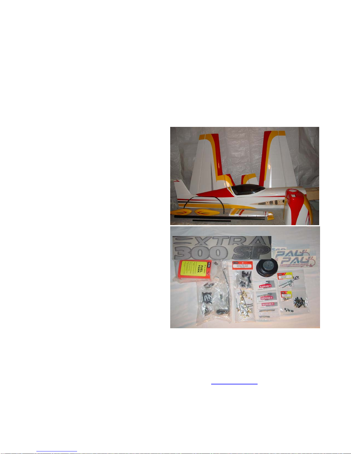
1 Fuselage
1 Fuselage access hatch
2 Wing panels (1 right and 1 left)
2 Horizontal stabilizers (1 right and 1 left)
1 Rudder
1 Fiberglass Cowl
1 Pair of fiberglass wheel pants
1 Carbon Fiber landing gear
1 Pair of Sullivan or Dubro Light wheels
1 Tail wheel and tiller assembly
1 Canopy
1 Carbon fiber wing tube
1 Carbon fiber stabilizer tube
4 Nylon wing retention bolts
6 H9 titanium pushrods/turnbuckles
1 set of Dubro wheel collars
1 pair of Dubro wheel axles
1 HD pull-pull system
1 Set of aluminum control horn assemblies
1 32oz Dubro fuel tank
8 HD 4/40 Dubro ball links
1 Set of additional various marked hardware
1 Vinyl graphics package (2 PAU, 2 Extra)
If any of these parts are missing immediately contact PAU.
If you need more information you can visit our support forum at: flyinggiants.com

4
Chapter 2
Preparation for Assembly
Professionals utilizing premium Ultracote covering carefully covered your model. Due to climate changes
during shipping, the models covering may have loosened and/or winkled. It’s a good habit to go over your
model with a covering iron to ensure all joints, seams, and edges are properly sealed.
Ultracote is a lower temperature film that seals and shrinks at lower temperatures. Make sure you set your iron
on a low temperature initially to get a feel for the correct temperature setting and adjust accordingly. Higher
temperatures will cause your covering to over shrink and distort. Also, use a sock over your iron to ensure a
scratch free finish.
Place an “” to ensure task completion:
Go over you model as necessary with a covering
iron to insure all joints, seams, and corners are
sealed properly.
Use your iron to ensure the areas where cutouts are
needed for your hardware are located and sealed
down, such as servos; tubes, and control horn
mounting locations.
Next, we’ll need to cut out the covering at the locations for hardware and final assembly. Make sure you use a
sharp hobby knife so your cuts will be clean and straight.
Start with the fuselage, locate and cut out the servo
and stabilizer and wing tube locations.
Locate and cut the location for the anti-rotation pins
and mounting holes for the stabilizers and wings.
Locate and cut the two mounting bolt locations for
the canopy and the two pull-pull exits.
Locate and cut the servo mounting locations for
each wing half.
5
Chapter 3
Landing Gear and Tail Wheel Assemblies
Now that we’re ready for assembly, we are going to start with the main landing gear first. You will need to
locate the following parts to begin assembly.
Place an “” to ensure task completion:
What you will need in this chapter for the main gear:
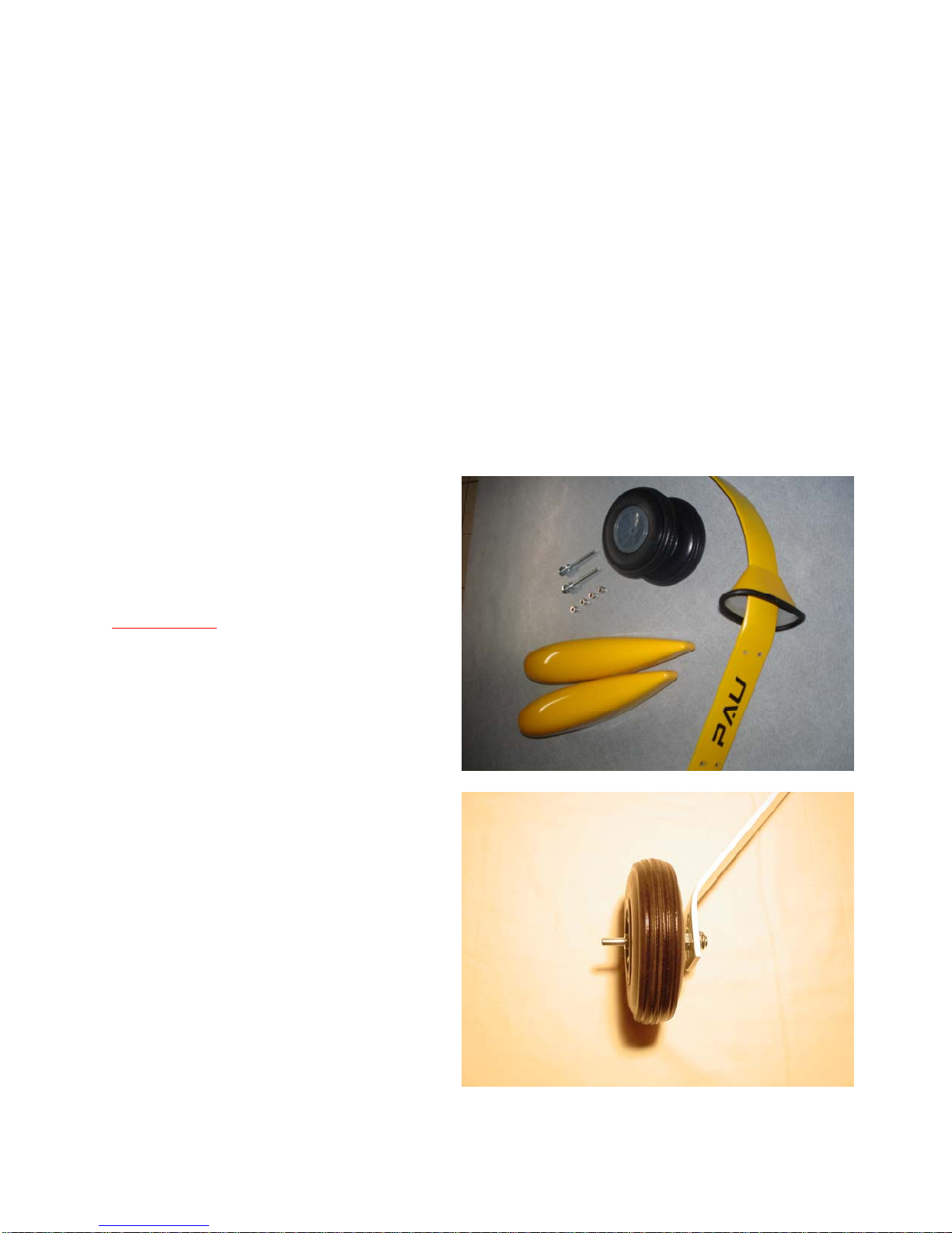
Carbon Fiber main gear
One pair of 4 inch wheels
One pair of wheel pants
One pair of Cuffs
Black neoprene fuel tubing 2’
One pair of Dubro axles
Four wheel collars
Hardware pack marked “wheels”
Fuselage
Rudder
Tail wheel assembly
Not Provided:
½” Black neoprene fuel tubing
½” and a 9/16” inch wrench
Blue loc-tite
Allen wrench for wheel collars
White wood glue such as Elmer’s or
Epoxy
Prep the cuffs: slice the supplied black
neoprene tubing lengthwise. Install on the
cuffs around the edge of the large opening
with the seam on the belly side. Glue from
inside the cuff with thin CA.
Temporarily slide the cuffs on the main
gear, and then fasten the axles to the main
landing gear with the lock nuts.
Using your four wheel collars and wheels,
center you wheels on the axles. Place the
collars as close to the wheels as possible but
ensure the wheels still rotate freely. Again,
we don’t want the wheel to move from side
to side and contact the wheel pants. Also,
we recommend the use of loc-tite on the setscrews of the wheel collars to prevent them from vibrating
loose.
6
First you’ll need to nock out
the plywood opening the
canister tunnel. Use a hobby
knife on the small area not
already cut with a laser and
lightly tap it out with a small
hammer.
Install the landing gear to the
fuselage using the four 8/32
bolts, spring washers,
and flat washers, and
compression nuts.
Secure the cuff into
place: put a thick
bead of silicone (not
included) in the main
gear where the
narrow end of the cuffs meets the main gear. Slide the cuffs up until they gently meet the fuse (it is best
to leave a 1/16” gap, so the cuffs don’t quite touch the fuse, so the cuffs do not damage the belly when
the gear flexes). Wipe off possible silicone excess and let cure.
Now let’s get the tail wheel assembly installed.
Once the mains are on, find the pre-drilled hole for the tail wheel assembly. Insert the tail wheel
assembly and lightly tap in flush with a small hammer.
Next, mark the hold down locations, drill and mount them with the four wood screws securing the tail
wheel assembly. Remove the wood screws and coat the holes with thin CA, let dry, reinstall.
Install the steel tiller horn just behind the hinge line on the bottom of the rudder using the two small
wood screws.

7
Tip#2 Set aside your two tiller springs, we will install those later after the rudder is mounted.
With the aircraft resting on the landing gear, we are going to need to set the right angle for the wheel
pants. We used wood scraps to position the wheel pants properly. Mark the drilling location for the 4/40
bolts.
Drill the holes for the 4/40 bolts in the wheel pants at the locations you’ve marked.
Apply some white wood or epoxy glue to the inner side of the four 4/40 blind nuts and install the blind
nuts to the inside of the wheel pants.
Now you can install the wheel pants with the 4/40 bolts and washers. Don’t forget to use loc-tite here
again. Wheel pants tend to take the most vibration.
8
Chapter 4
Canopy and Fuselage Hatch
Place an “” to ensure task completion:
Gather the following for canopy and hatch
installation:
Canopy
Fuselage and Access Hatch
8 small wood screws
Two 4/40 bolts with two sealing
washers
Not Provided:
Drill and small drill bit for wood
screws
Canopy glue (optional)
Thin CA
Ruler
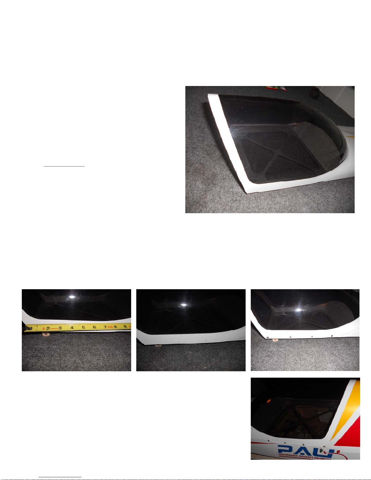
Install the hatch on the fuselage using two 4/40 bolts with the self-sealing washers.
Trial fit the canopy to the fuselage access hatch to determine screw locations.
Mark four evenly spaced locations for the screws on each side. Double check to ensure all the marked
screw locations will go into the hatch rail.
Remove canopy from the access hatch and drill the marked locations for the canopy screws.
Install the canopy using the small wood screws. If satisfied with the
fit, remove the canopy and hatch and wick a small amount of thin
CA into each of the screws holes on the hatch. Once dried, reinstall
canopy with optional canopy glue if desired. Cauton! CA will fog
the canopy if installed before completely drying.
Tip#3 If there is no need to remove the canopy from the hatch, you may
want to glue it: RC-56 glue was used on the prototype.
9
Chapter 5
Engine Installation
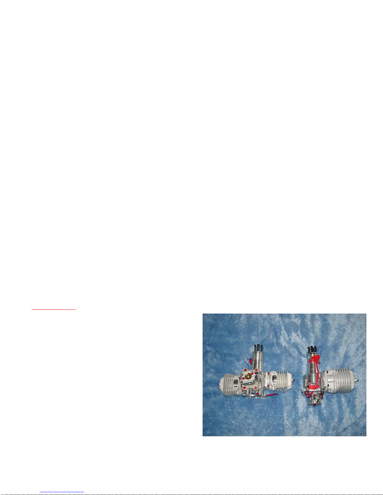
Your firewall is pre-mounted but our customers can select from a wide variety of engine choices. It is nearly
impossible to cover every engine installation choice in this manual but we’ll cover a few. Your aircraft was
designed around the 100cc twin gas motors. Also, we have provided a canister tunnel and a tuned pie tunnel on
our Extra for those who desire quieter operation. Please consult the manufacturer for the installation of optional
canister or tuned pipe.
Your Extra 300-SP will also accept lighter motors like the DA-85. If using the DA-85, attention should be paid
to your hardware installation as it may need to be mounted towards the front of the aircraft for proper CG.
We will cover the installation of two popular engine choices in this manual, the DA-85 and the DA-100 motors.
Follow your engine manufactures instructions for any additional guidance. Let’s get started!
Place an “” to ensure task completion:
What you will need in this chapter:
A DA-100 mounting template found in the back of this manual or a DA-85 mounting template found
in the back of the DA-85 manual.
Not Provided:
1/2” standoffs for the DA-100
1-1/8” mount for the DA-85
Four ¼-20 bolts 1-3/4” long for the DA-
100
Four ¼-20 bolts 2-1/2” long for the DA-
85
Four lock or compression nut with fender
washers
An engine in the recommend size range
4 ½ inch spinner
Propeller
A drill and drill bits
Center punch
Scotch tape for template

10
DA-100 installation
The firewall is pre-marked so you'll just need to center your motor in the "+". Take a ruler and draw a
line across the entire firewall for the thrust line and offset centerline.
DA-100 users only. If using the DA template provided on the last page of this manual, check the
measurements on the template and ensure the holes are correct. Cut the paper template to the size
needed to tape it to the firewall using your thrust line and offset centerline as a guide. Mark the drilling
locations and drill holes for 1/4-20 bolts.
Mount the motor using 1/2" standoffs for the DA-100, and four 1/4-20 x 1-3/4" long bolts.
Now that you have the motor mounted, mark the locations for the fuel line and throttle push rod remove
motor and drill those locations and reinstall motor.
Tip #4 We recommend 4/40 push rods for throttle and/or optional choke servo. Also ensure there is no
metal-to-metal contact from the throttle/choke to the servos. 2/56 Ball links for 4/40 rod (not included) will
prevent the aforementioned metal-to-metal contact and will bolt to nicely to your motors carburetor.

11
DA-85 installation
You will just need to center your motor in the "+". Take a ruler and draw a line across the entire
firewall for the thrust line and offset centerline.
DA-85 users only. If using the DA template provided on the last page of your DA manual, check the
measurements on the template and ensure the holes are correct. Cut the paper template to the size
needed to tape it to the firewall using your thrust line and offset centerline as a guide. Mark the drilling
locations and drill holes for 1/4-20 bolts.
Desert aircraft recommends not using standoffs with the DA-85. You will need to make a mount to
properly install this motor. We used the template provided by DA and made several light plywood rings
stacked to achieve the correct standoff, which is approximately 1-1/8” off the firewall.
Mount the motor using 1-1/8" solid mount for the 85, and four 1/4-20 x 2-1/2" long bolts.
Now that the motor is mounted, mark the locations for the fuel line and throttle push rod remove motor
and drill those locations and reinstall motor. Another recommended option is to use the template and cut
a hole in the firewall for the carburetor, which will make installing push rods and fuel lines easier.
We recommend 4/40 push rods for throttle and/or optional choke servo. Also ensure there is no metal-to-
metal contact from the throttle/choke to the servos. 2/56 Ball links for 4/40 rod (not included) will prevent
the aforementioned metal-to-metal contact and will bolt to nicely to your motors carburetor.
12
Chapter 6
Cowling installation
Place an “” to ensure task completion:
What you will need in this chapter:
Fuselage and cowling
Five 6/32 bolts with spring and lock washers
Not Provided:
A 4-½ inch spinner
A Dremel tool
A facemask and eye protection
Pencil or dry erase marker
Always wear a mask and eye protection while cutting fiberglass. Take your time while installing the cowl.
With care you will end up with a professional installation that will make an impression at the field.
Close the choke and place a piece of tape over the carburetor inlet and exhaust outlet to keep out any dust while
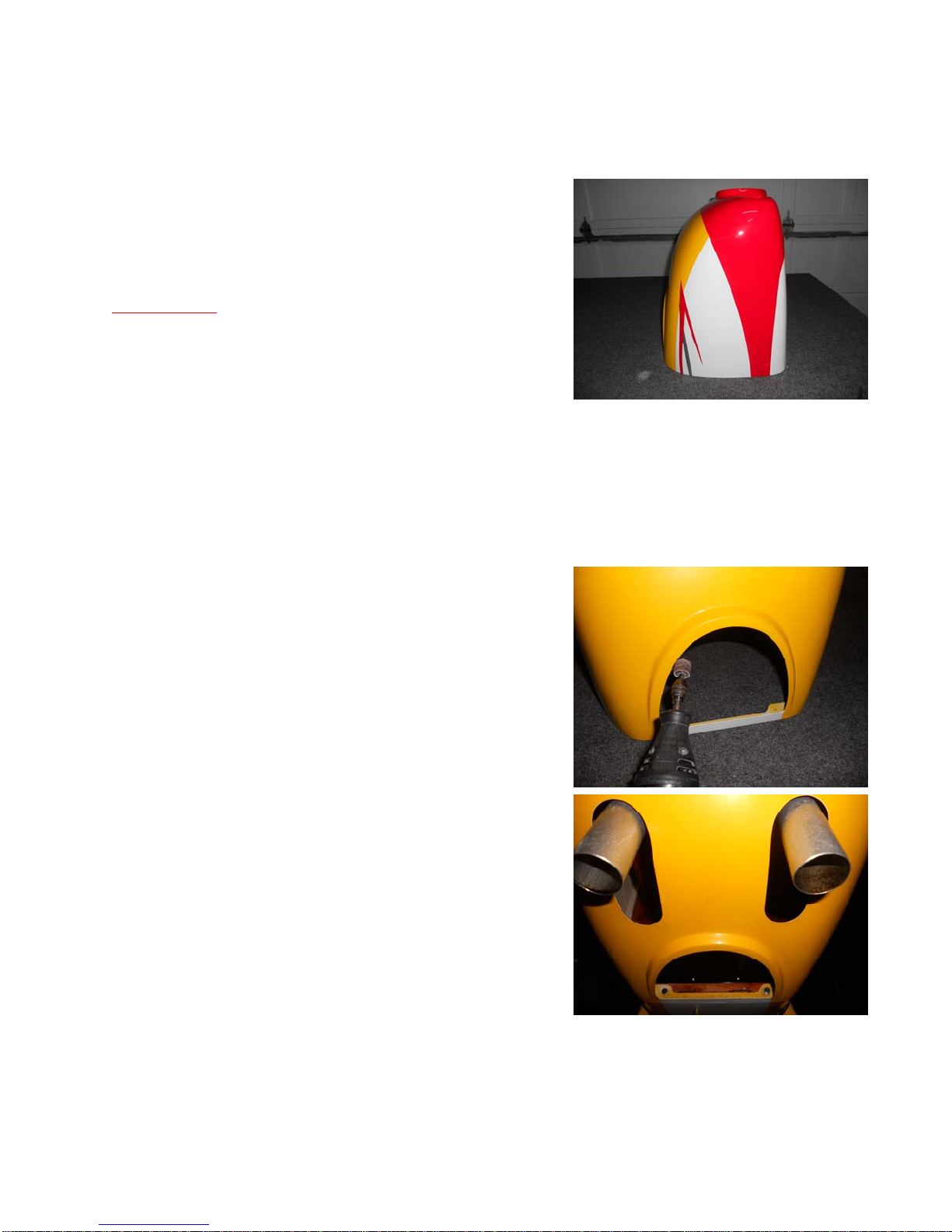
setting up your cowl. Since the cowl is preset and uses a ring to mount, there will not be much to do here.
First cut out the bottom opening for cooling. For the DA-
100 using canisters, you will only need to open the bottom
of the cowl to exit the air from the cowl. If you’re using
stock exhaust stacks, it maybe necessary to cut away the
bottom portion of the cowl ring for it to pass the exhaust.
If using stock mufflers for the DA-100, we recommend the
compact style.
For the DA-85, measure and cut an opening for the
cylinder head and muffler just enough to get the cowl
mounted.
Now we are ready to do some fine trimming for the DA-85.
We will want to cut at least an extra 1/4 inch cut around
any of the engine components that protrude. Mark any
additional areas that may require trimming.
Remove the cowling and cut out the remaining areas to be
trimmed.

13
Chapter 7
Rudder Installation
Place an “” to ensure task completion:
What you will need in this chapter:
Rudder and fuse
Pull-pull hardware
Not Provided:
30 to 45 minute epoxy
Two cycle oil
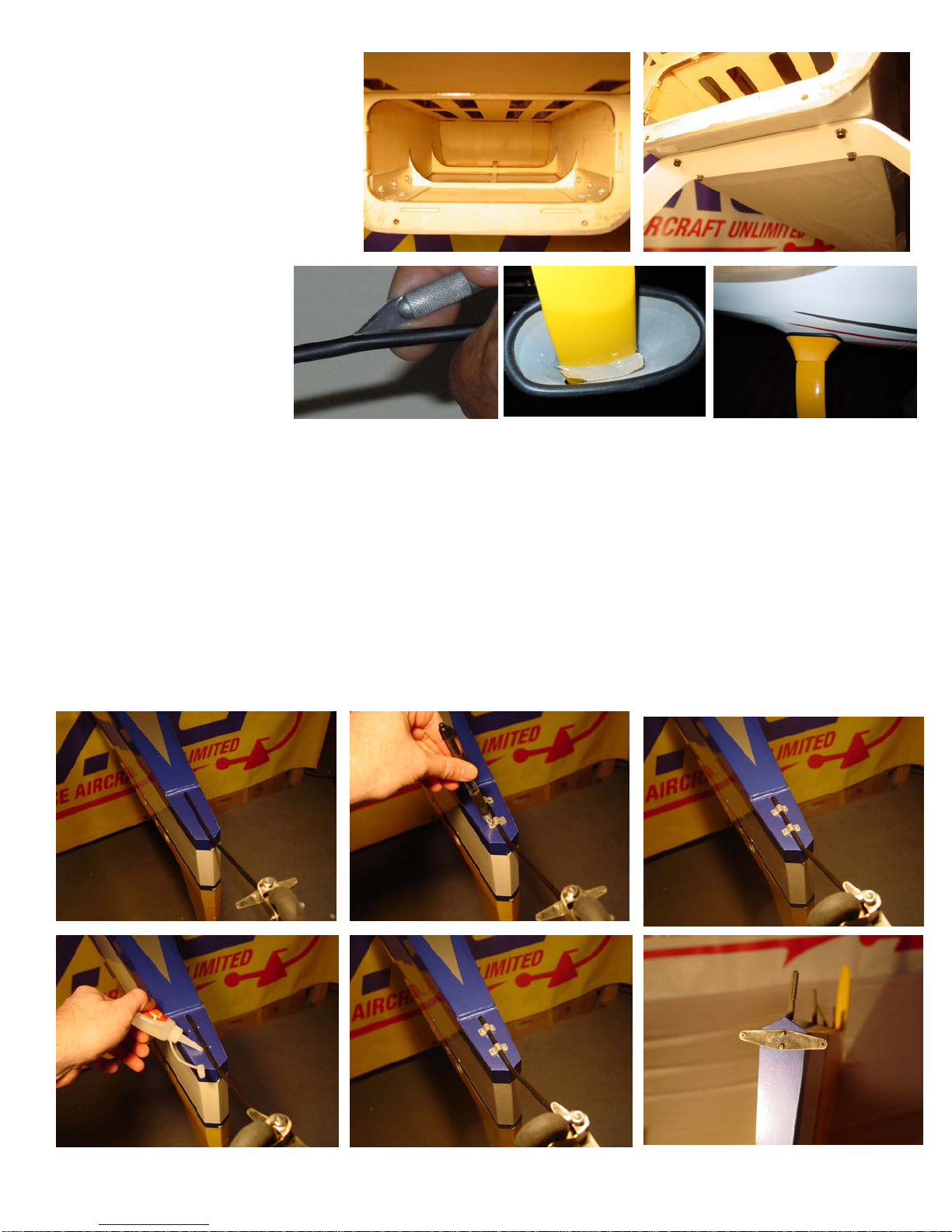
Next, we will install the hardware on the rudder before
mounting the rudder. Find the pre-drilled hard point, remove the covering and insert the longer 4-1/2”
stainless threaded rod provided.
Install the Dubro fasteners to the rod. Use loc-tite as
shown if you are not planning on using the lock nuts.
Now add the control horns placing them at 2” from the
hinge line.
Now were going to prep the hinges for installation. Take a
small drop of oil and place it in each of the pivot points of
your hinges. The oil prevents excess epoxy from bonding
the joint.
Apply epoxy into the trailing edge holes of the vertical
stabilizer. Now apply epoxy to the hinges.
Carefully insert the control surface into the stabilizer and
butt the two surfaces together. Move the surface back and
forth a couple of times to make sure all the hinges are
aligned correctly and the desired throw is attained. You
will want at least 45 degrees.
Use some masking tape to hold the surfaces together and
let cure for at least eight hours.
Install the tiller springs you set aside in chapter 2 to the tiller horn and tiller.
Tip#5 Optional step. After your epoxy has cured, it would be a good time to seal all of your hinge gaps prior
to installing the rest of the hardware. This can provide you with a better flying aircraft by increasing control
surface performance and preventing possible flutter. Clear or matching covering material can be ironed in
place to fill any gaps on the bottom of your control surfaces.
Take approximately a one-inch strip of covering the length of your surface. Fold it in half while placing into
the gap with the control surface fully deflected up and iron it in place. Check to make sure you still have full
surface travel once you have completed.
14
Chapter 8
Hardware Installation
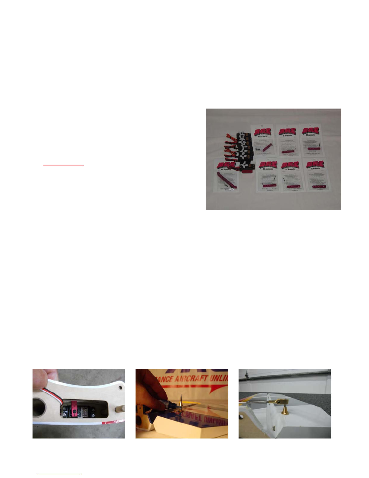
We provide high quality aluminum control horn assemblies included with our latest generation of PAU aircraft
kits. We believe these lightweight assemblies are the best available and can also be purchased separately from
PAU. Place an “” to ensure task completion:
What you will need in this chapter:
The entire airframe
Six H9 titanium push rods
Six sets of aluminum control horn assemblies
Six steel posts
Eight HD Dubro ball links
One 32oz Du-bro fuel tank
Not Provided:
Four 150oz or better servos for ailerons
Two 200oz or better servos for elevators
One or two servos for rudder totalling 400oz
One throttle servo 70oz or better
Six 1.5” aluminum servo arms
One 4” offset rudder servo arm
One Fuel dot or other fueling device
Some foam rubber for mounting receiver, ignition module, and fuel tank
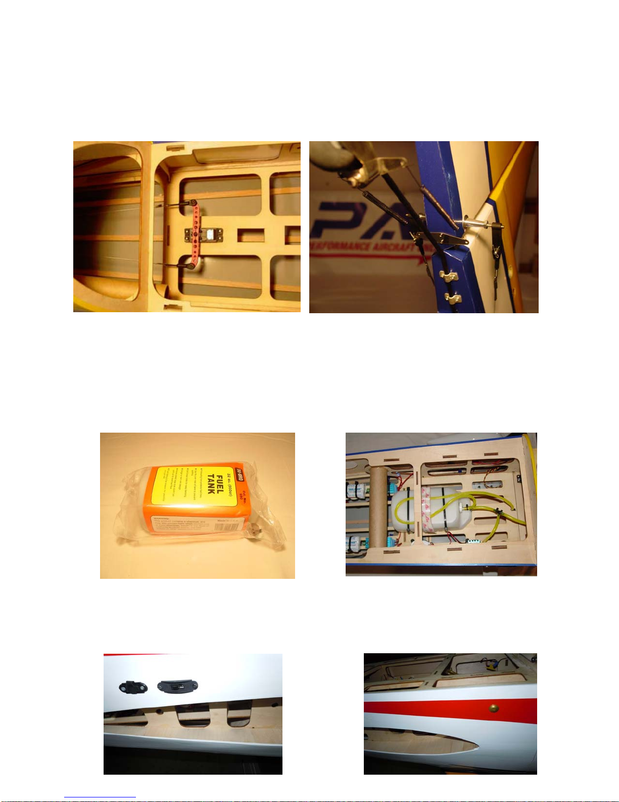
Install all your flight control servos with the output shaft closest to the control surface.
Install 150oz or better servos for the ailerons in the servo trays located in the bottom of the wings.
Install 200oz or better servos for the elevators in the servo trays located in the bottom of the horizontal
stabilizers.
Install one or two equaling 400oz or better servos for the rudder in the servo tray inside the fuselage.
Install your throttle and or choke servos in the forward bays provided.
First you need to find the pre-drilled holes for the steel posts. Install the aluminum control horn
assemblies to each surface with the M4 bolt in the down position. Use blue loc-tite on the aluminum
base to ensure the bolt does not try to back out under vibration. Screw on the horns on to the posts.
Do not use loc-tite installing the horn.
15
Make sure your elevator servos are centered and mount
your servo arms parallel to the hinge line.
Take some masking tape and tape the elevator counter
balances to the stabilizers so that they are in a center
position.
Screw in your two HD ball links onto the counterclockwise
ends of the 2” H9 push rods and screw the other end into
the control horn. Ensure everything is still centered. Don’t
forget to add locknuts to the 4/40 bolts when attaching the
ball link to the arm.
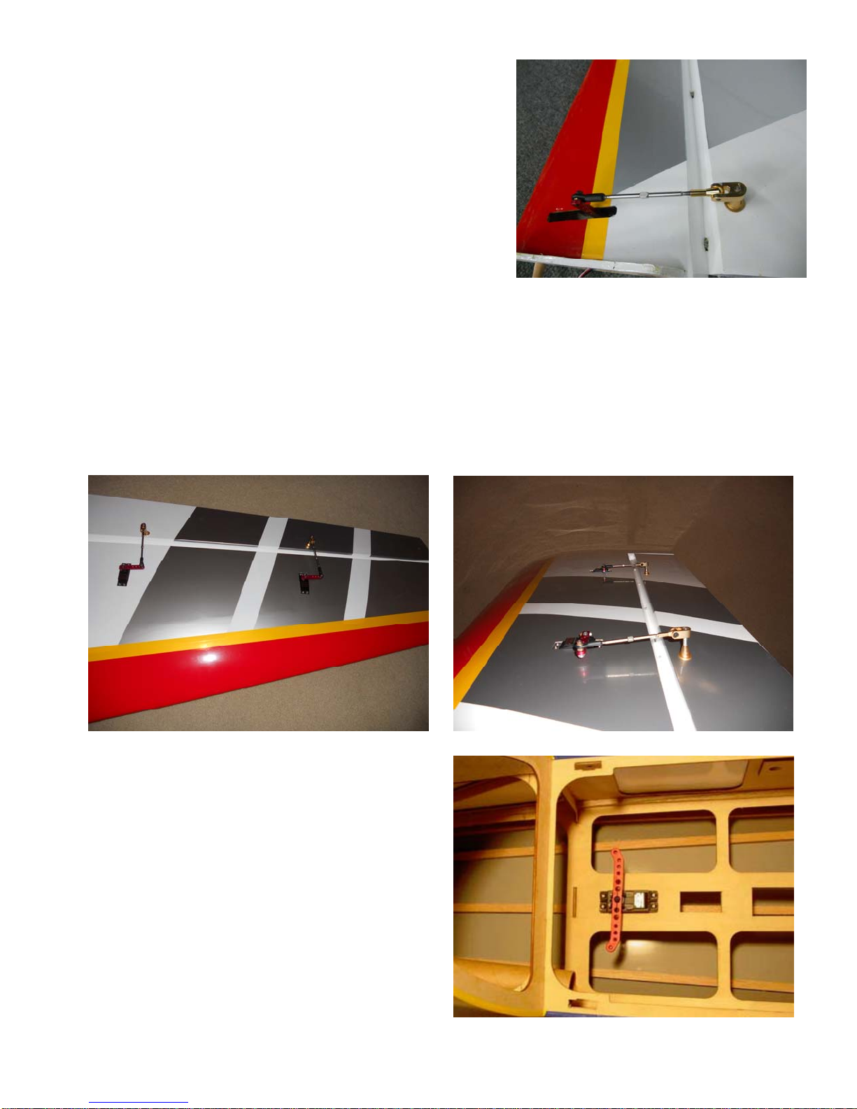
Ensure aileron servos are centered and mount your arms parallel to the hinge line.
Be sure that you install the horns at the same height from the hinge line (see attached). By doing so you
will have very little servo matching to do afterwards.
Screw in four HD ball links onto the counterclockwise ends of the 3” H9 push rods and screw the other
end into the control horn. Ensure everything is still centered. Don’t forget to add locknuts to the 4/40
bolts when attaching the ball links to the arms.
Ensure your rudder servo is centered and mount
your rudder servo arm.
A single JR 8711 or dual Futaba 9156 have been
used in prototypes. If you’re using two servos,
you will need an additional servo arm to tie the
two servos together as well as a servo matching
device.
16
Install your pull-pull cable and your remaining pull-pull hardware. Cables should be crossed to avoid
any rubbing on the exits. It is normal for the non-pulling side of the cable to slacken a little when the
rudder is deflected.
Install your tiller springs you set aside earlier.
Assemble the fuel tank according to the directions provided on the package. You will need to decide
whether you want a two or three-line setup. With a two-line setup you will need an additional “T”
fitting in the carburetor line that connects to your fuel dot or fueling device. Make sure you use Tygon
fuel tubing inside the tank for the clunk as well.
Install the fuel tank just in front of the wing tube using zip-ties or hook and latch (Velcro) straps. Place
a loop in the vent line over the top of the tank to prevent fuel loss during flight and improve flight times.
Take small zip-ties or fuel line clamps and fasten to all the points where the fuels lines connect.
Install the switches the location of your choice. In most cases, there are pre-cut locations at the front of
the fuse sides. The prototype was also fitted with external charge jacks for battery checking at the field.
Install the fuel-filling device in a location of your choice. In this case, we installed it just behind the
cowl.
17
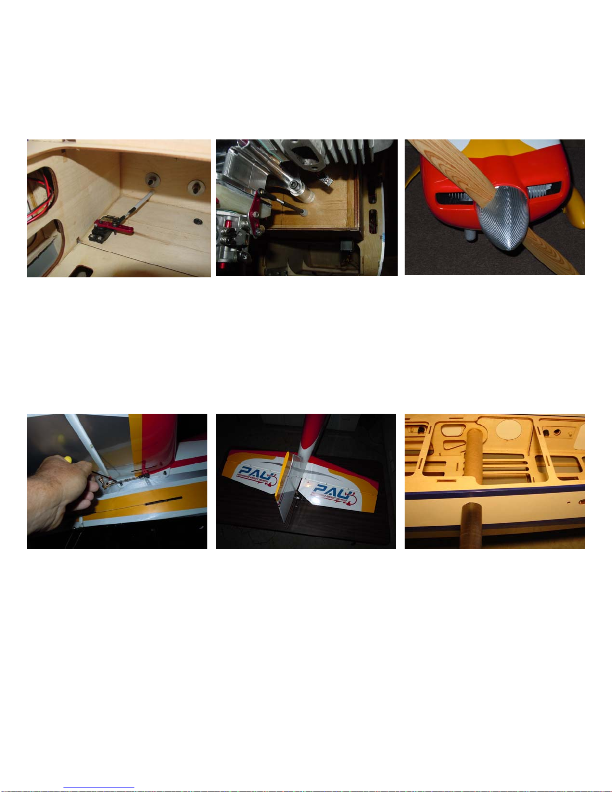
Install your throttle push rod. Again as mentioned earlier, we do not want metal-to-metal contact at the
attachment point on the engine. Use a 4/40-rod with a 2/56 ball link for 4/40 rod to attach the push rod
to the motor.
Once satisfied with your throttle setup, mount the cowl using the five 6/32 bolts provided and attach the
prop and spinner.
Install the horizontal stabilizers at this time. Install the carbon fiber stabilizer tube. Slide in each half
and secure them with the four 4/40 retention bolts.
Install the horizontal stabilizers at this time. Install the carbon fiber stabilizer tube. Slide in each half
and secure them with the four 4/40 retention bolts.
Let’s install the wings at this time and check our center of gravity (CG). Install the carbon fiber wing
tube. Slide in each wing panel and secure them with the four nylon wing retention bolts.
Tip#6: Depending on climate conditions, the wing tube may be too tight or too loose. If the wing is tight you
can coat the tube with a little baby powder to aid the insertion of the wing panels. If still too tight, warp a
sheet of sand paper around a dowel covered with a foam pad, and sand the inside of the socket. DO NOT
sand the CF tube. If too loose, add some wide packing tape to the surface of the wing tube.
Tip#7: For added protection in case the wing retention bolts back out during flight; you can add hitch pins to
the anti-rotation pins of the wing. With the wings installed, mark the anti-rotation pins ¼ inch from the
fuselage side. Remove the wings and drill a small hole in the anti-rotation pins. You can find appropriate
sized hitch pins at most local hardware stores. Re-install wings and insert the hitch pins for added
protection.
18
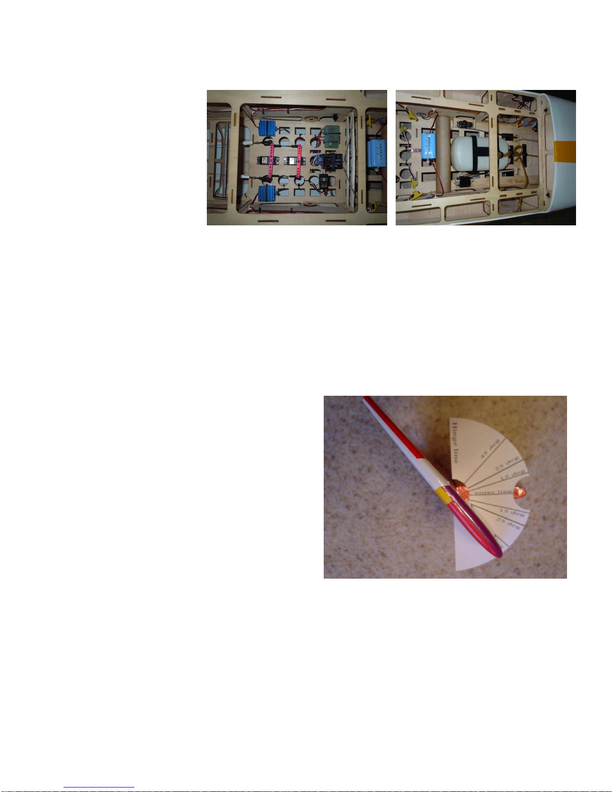
Now we’re ready to check the CG and install your remaining hardware. The CG range is center of the wing
tube, plus or minus 1/2”. We recommend to center with the wing tube for initial flights. The photos below
show the final set up for our preferred CG after test flights.
Check CG at this time
and place your batteries
and remaining hardware
in locations to attain the
desired CG. If satisfied
mount your remaining
hardware.
Congratulations! You have just
completed assembly of your
Edge540. Now would be a good time to install the optional vinyl graphics included with your kit.
Chapter 9
Radio and Control Surface Setup
Now we are ready to setup your aircraft for flying. Included is this manual are templates for measuring surface
throw you may use if desired. We recommend that you setup your aircraft on low rates for initial flights until
you become familiar with the aircraft and its capabilities.
The recommended low rates for this aircraft are:
25 degrees for ailerons with 0 to 20% expo
15 degrees for elevators with 0 to 20% expo
30 degrees for rudder with 0 to 20% expo
The recommended high rates for this aircraft are:
35 degrees for ailerons with 40 to 70% expo
45 degrees for elevators with 40 to 70% expo
45 degrees for rudder with 30 to 70% expo
or as much as you can stand for hardcore flyers.
CG Range is 6 to 7 inches.
Place an “” to ensure task completion:
What you will need in this chapter:
Completed airframe
Radio
Throw templates or meter
Cut out the templates for surface throw. These should be located on the last page of this manual.
Tape each one in place using the horizontal line as a reference point to each stabilizer at the counter
balance and at the inside of the wings where the ailerons meet.
Set your throws accordingly. Double check to make sure nothing is binding to include the throttle and
or choke servos and their linkages. Also, ensure all surfaces and controls are moving in the proper
directions.

19
Chapter 10
Final Inspection and Pre-Flight
Welcome to the final chapter prior to your maiden flight. We hope you have enjoyed building your Edge 540.
Lets go over the airframe and perform a pre-flight to make sure everything is in order.
Inspect the airframe for any visible damage and loose covering that may have occurred during the build.
Inspect the main landing gear and tail wheel assembly. Ensure all mounting hardware and collars are
fastened properly.
Inspect your motor installation and cowl to ensure all bolts are tight and the muffler is firmly mounted in
place. Check the motor and muffler for possible contact with the cowl. Inspect ignition module and
spark plug wire for proper mounting. Check propeller and spinner to ensure they are both secure.
Inspect the inside of the fuselage to ensure your batteries, switches, regulators (if equipped), fuel tank
and lines are securely fastened. Check nylon wing bolts to ensure they are in place and secured.
Inspect all control surfaces and control surface hardware. Gently tug on each surface to make sure the
hinges are properly bonded. Check the four 4/40 horizontal stabilizer fasteners and ensure they’re in
place and secured.
Check all servos for mounting screws. Check servo arm mounting screws and inspect that the 4/40 links
have been secured with lock nuts.
Fill fuel tank and inspect for any leaks.
Check your batteries in both your aircraft and radio to ensure they are fully charged
Turn on radio to inspect all controls for binding, proper direction and throw while on high rates.
Re-check CG. It should be anywhere from 6 to 7 inches depending on your flying style.
Secure aircraft using a buddy or hold down and start motor according to manufacturers guidelines.
Don’t forget to lower your throttle prior to ignition.
Perform a proper range check with the motor running using your radio manufacturers instructions.
Make sure you go back to low rates for your maiden takeoff and enjoy!
This concludes your pre-flight checks. After your maiden flight, repeat these steps to perform a post flight to
ensure nothing has loosened. It’s always a good habit to use a checklist like this one to go over your aircraft
prior to the first flight of the day.

20
Flying!
We believe you will find this aircraft finest aircraft you’ve ever flown. High-alpha stability gives you solid
control and confidence to bring it right down on the deck! For contest flying such as IMAC, a 6-1/2” CG offers
great precision and our airframe is a great choice.
Every airplane has structural limits, and the larger the plane is, the more critical it is to understand and
respect these limits. This is particularly true for 3D aerobatic planes, since by design, these planes are light
weight, are over powered, and have oversized control surfaces.
Pilots need to use proper throttle management, and avoid high speed when executing high stress maneuvers
such as Walls, Parachutes and Blenders. As a general rule, the throttle must be at idle position whenever the
nose is pointed down (whether at vertical or 45 degrees down line).
Planes must be inspected frequently, looking for any loosening screws, bolts and glue joints. Servos and
linkages must be free of play or “slop”, as this is a major cause of flutter (and crashes).
Understanding and applying these few safety and maintenance
We hope this aircraft offers you many years of enjoyment. Thank you again for choosing PAU and look for
exciting future products.
Additional products from PAU:
27% Pitts Challenger
27% Pitts Bulldog
30% Sukhoi SU-26M
30% Edge 540
30% Extra 300-SP
36% Edge 540
43% Edge 540
37% Ultimate
123”, 150cc Extra 300-SP
A complete line of high performance PAU laminated propellers.
Nolimitz Fiberglass and Carbon Fiber spinners.
Single Bolt Carbon Fiber spinners.
Aluminum Hardware sets that weighs next to nothing. Time to chuck your old stuff, its now obsolete!
Other great designs are on their way! Stay tuned.
Table of contents
Other PAU Toy manuals


Popular Toy manuals by other brands

Beyblade
Beyblade Dranzer S instructions

Mattel
Mattel Barbie GML79 instructions

BNF
BNF BLADE UMX F27 FPV instruction manual

Mega Construx
Mega Construx Call of Duty DPB60 instructions

Hasbro
Hasbro Star Wars Legacy Collection Millennium Falcon... instruction manual

Enabling Devices
Enabling Devices 2001 user guide


E-FLITE
E-FLITE Blade mCX instruction manual

Trix
Trix UP 844 manual

Northeast Aerodynamics
Northeast Aerodynamics 2M Aquila F3A Assembly manual

Hasbro
Hasbro Transformers Energon Six Shot 80450 instruction manual

Hasbro
Hasbro G.I. Joe Sting Raider instructions

ATOMIC MASS GAMES
ATOMIC MASS GAMES MARVEL BARON STRUCKER AND ARNIM ZOLA Assembly guide