PAU Edge 540T User manual

Property of Performance Aircraft Unlimited
Property of performance Aircraft Unlimited 1
50/60cc Edge 540T
Instruction Manual
Congratulations and thank you for purchasing the Performance Aircraft Unlimited 50/60cc Edge 540. The
Zivko Edge 540 was designed and developed to be the best aerobatic aircraft in the world and it delivered! Not
only does this aircraft dominate IAC competition but has also found a home in the Red Bull racing circuit where
it has won title after title. The 540 stands for the powerful Lycoming 540 motor that puts out more than 300hp.
Made from modern composites, this aircraft is sure to be on the podium for some time to come.
The PAU Edge is no different! Designed with 1474 sq inches of wing area while keeping the total weight down
has made this aircraft a true performer. All wood construction and top quality hardware make it hard to beat. If
you want an aircraft precise enough to compete in IMAC or to turn it loose for the wildest 3D maneuvers on the
planet, the PAU Edge’s are the only choice. PAU has also increased the aileron size and really beefed up
the wings. The fuse is redesigned and has a much more aggressive stance. More side area and stubble surface
changes clean this aircraft up further in knife. Just as it’s full-scale counterpart, the PAU Edge has found victory
in competition aerobatics.

Property of Performance Aircraft Unlimited
Property of performance Aircraft Unlimited 2
We believe you will find this to be one of the finest flying scale Edge on the market. Most modelers will find
assembly of this aircraft simple and straightforward. We recommend the builder follow the step-by-step
instructions to achieve the best performance and to ensure nothing was over looked. This manual also includes
tip sections throughout that may help you in key areas during assembly. Please familiarize yourself with this
manual before assembly.
This aircraft is fairly large for a 50cc aircraft so users are cautioned of adding unnecessary accessories can add
to the aircrafts total weight. A little here and a little there, it all adds up! Keep it simple, keep it light!
This manual is broken down into ten chapters for simplicity:
Chapter 1 - Parts Inventory
Chapter 2 - Preparation for Assembly
Chapter 3 - Landing Gear and Tail Wheel Assemblies
Chapter 4 - Canopy and Fuselage Hatch
Chapter 5 - Engine Installation
Chapter 6 - Cowling Installation
Chapter 7 – Control Surface Installation
Chapter 8 - Hardware Installation
Chapter 9 - Radio and Control Surface Setup
Chapter 10 - Final Inspection and Pre-Flight
Additional items needed to complete this aircraft, which are not included:
An engine, within the recommend range, and propeller
8 channel computer radio and receiver recommended
Batteries and switches (with regulators if using Ion batteries)
Two aileron servos rated at least at 250oz of torque
Two elevator servos rated at least at 200oz of torque each
One or two rudder servo rated at least at 250oz of torque
One throttle servo with push rod and links
Optional choke servo with push rod and links
One fueling dot or fueling device
3 to 4 feet of fuel tubing
Foam rubber
3-1/2 inch spinner
30 to 45 minute epoxy
A bottle of thin CA
Covering iron
Various modeling tools for assembly
½ inch low tack masking tape

Property of Performance Aircraft Unlimited
Property of performance Aircraft Unlimited 3
Chapter 1
Parts inventory
Place an “×
××
×” to ensure your kit is complete:
1 Fuselage
1 Fuselage access hatch
2 Wing panels (1 right and 1 left)
2 Horizontal stabilizers (1 right
and 1 left)
1 Rudder
1 Fiberglass Cowl
1 CF landing gear
1 Pair wheel pants and cuffs
1 Pair of wheels
1 CF Tail wheel and tiller
assembly
1 Carbon fiber wing tube
1 Carbon fiber stabilizer tube
2 Nylon wing retention bolts
4 titanium pushrods/turnbuckles
1 set of Dubro wheel collars
1 pair of Dubro wheel axels
1 HD pull-pull cable
1 Set of aluminum control horn assemblies
1 20oz Dubro fuel tank
6 HD 4/40 Dubro ball links
1 Set of additional various marked hardware
If any of these parts are missing immediately contact PAU.
If you need more information you can visit our support forum at: www.flyinggiants.com
This manual is strict property of Performance Aircraft Unlimited.

Property of Performance Aircraft Unlimited
Property of performance Aircraft Unlimited 4
Chapter 2
Preparation for Assembly
Professionals utilizing premium Ultracote covering carefully covered your model. Due to climate changes since
shipping, the models covering may have loosened and/or winkled. It’s a good habit to go over your model with
a covering iron to ensure all joints, seams, and edges are properly sealed.
Ultracote is a lower temperature film that seals and shrinks at lower temperatures. Make sure you set your iron
on a low temperature initially to get a feel for the correct temperature setting and adjust accordingly. Higher
temperatures will cause your covering to over shrink and distort especially the trim pieces. Also, use a sock
over your iron to ensure a scratch free finish.
Place an “×
××
×” to ensure task completion:
Go over you model as necessary with a
covering iron to insure all joints, seams,
and corners are sealed properly.
Use your iron to ensure the areas where
cutouts are needed for your hardware are
located and sealed down, such as servos;
tubes, and control horn mounting
locations.
Next, we’ll need to cut out the covering at the locations for hardware and final assembly. Make sure you use a
sharp hobby knife so your cuts will be clean and straight.
Start with the fuselage, Locate and cut out
the servo and stabilizer and wing tube
locations.
Locate and cut the location for the anti-
rotation pins and mounting holes for the
stabilizers and wings.
Locate and cut the two mounting bolt
locations for the canopy and the two pull-
pull exits.
Locate and cut the servo mounting
locations for each wing half.

Property of Performance Aircraft Unlimited
Property of performance Aircraft Unlimited 5
Optional step
Side windows and rear inspection glass.
Included with you kit are optional lower pilot side windows and the rear inspection windows. This adds
a nice touch to your aircraft and gives a little more scale uniqueness.
Locate the windows in your kit.
Using a sharp exacto knife, locate the window frames
in the fuse and carefully cut through the covering and
into the laser cut lines in the fuse.
Remove the covering and carefully remove the wood
within the frame.
Test fit the windows, as
some slight trim work may be
required. Once your happy with
the fit, remove the protective
plastic backing from the window
and glue in place. We
recommend glue like RC-56 as
it’s very strong and will dry clear. CA will fog and is not
recommended.
Once windows are installed, you may wish to use ¼” trim and frame
the window. This will give you a very clean install and look.

Property of Performance Aircraft Unlimited
Property of performance Aircraft Unlimited 6
Chapter 3
Landing Gear and Tail Wheel Assemblies
Now that we’re ready for assembly, we are going to start with the main landing gear first. You will need to
locate the following parts to begin assembly. We tried to keep the landing gear in a scale location while
providing a canister tunnel.
Place an “×
××
×” to ensure task completion:
What you will need in this chapter for the main gear:
Carbon fiber main gear
One pair of 3.5 inch wheels
One pair of Dubro axles
Four wheel collars
Hardware pack marked “main wheels”
Fuselage
Rudder
Tail wheel assembly
Not Provided:
½” and a 9/16” inch wrench
Blue loc-tite
Allen wrench for wheel collars
Use a small soldering iron and open the holes for the
main gear bolts.
Install the landing gear to the fuselage using the four
8/32 bolts, spring washers, and flat washers, and
compression nuts.
Fasten the axles to the main landing gear with the
lock nuts.
Using your four wheel collars and wheels, center you
wheels on the axles. Place the collars as close to the
wheels as possible but ensure the wheels still rotate
freely. Again, we don’t want the wheel to move from
side to side and contact the wheel pants. Also, we
recommend the use of loc-tite on the setscrews of the
wheel collars to prevent them from vibrating loose.

Property of Performance Aircraft Unlimited
Property of performance Aircraft Unlimited 7
Now lets get the tail wheel assembly installed.
Using the pre-marked holes as a guide, drill the two holes
needed for the 6/32 bolts in the CF tail wheel bracket.
Install the bracket with the two 6/32 bolts provided with
blue loc-tite.
Tip#2 Set aside your two tiller springs, we will install those
later after the rudder is mounted.
Cut out the center wheel opening on the wheel pants on
the side with the wood-mounting block.
With the aircraft resting on the landing gear, we are going
to need to set the right angle for the wheel pants. We used
a standard servo and placed it at the end of the pant
resting the end on the rubber grommets of the servo.
Mark the drilling location for the 6/32 bolts.
Drill the holes for the 6/32 bolts in the wheel pants at the
locations you’ve marked.
Apply some white wood or epoxy glue to the inner side of the four 6/32 blind nuts and install the blind
nuts to the inside of the wheel pants.
Now you can install the wheel pants with the 4/40 bolts and washers. Don’t forget to use loc-tite here
again. Wheel pants tend to take the most vibration.

Property of Performance Aircraft Unlimited
Property of performance Aircraft Unlimited 8
Chapter 4
Canopy and Fuselage Hatch
Place an “×
××
×” to ensure task completion:
Gather the following for canopy and hatch
installation:
Canopy
Fuselage and Access Hatch
8 to 16 #2 wood screws
Two 6/32 bolts with two sealing washers
Not Provided:
Drill and small drill bit for wood screws
8 to 16 #2 wood screws
Canopy glue (optional)
Thin CA
Ruler
Install the hatch on the fuselage using four 6/32 bolts with the self-
sealing washers.
Trial fit the canopy to the fuselage access hatch to determine screw
locations.
Mark eight evenly spaced locations for the screws on each side.
Double check to ensure all the marked screw locations will go into
the hatch rail.
Remove canopy from the access hatch and drill the marked
locations for the canopy screws.
Install the canopy using the small wood screws. If satisfied with
the fit, remove the canopy and hatch and wick a small amount of
thin CA into each of the screws holes on the hatch. Once dried,
reinstall canopy with optional canopy glue if desired. Caution!
CA will fog the canopy if installed before completely drying.
The Edge 540T requires more screws due to it’s size. We do
recommend gluing it down. Use matching electrical tape and place
on the front lip to keep air from going under the canopy.

Property of Performance Aircraft Unlimited
Property of performance Aircraft Unlimited 9
Chapter 5
Engine Installation
Your firewall is pre-mounted but our customers can select from a wide variety of engine choices. It is nearly
impossible to cover every engine installation choice in this manual. Your aircraft was designed around the 50cc
to 60cc gas motors. Also, we have provided a canister tunnel on your Edge for those desire quieter operation.
Please consult the manufacturer for the installation of optional canister.
We will cover the installation of the DA 50/60cc motor. Follow your engine manufactures instructions for any
additional guidance. Lets get started!
Place an “×
××
×” to ensure task completion:
What you will need in this chapter:
A DA-50/60 mounting template found in the back of this manual.
Not Provided:
3” standoffs for the DA-50
Four ¼-20 bolts for the DA-50
Wood layered standoff for DA-60
Four lock or compression nut with
fender washers
An engine in the recommend size range
3-1/2 inch spinner
Propeller
A drill and drill bits
Center punch
Scotch tape for template
Also with the engine is installed, you will want the spinner back plate at lease 1/8th of an inch off the cowl for
proper engine placement. You may need to add a washer or two to achieve the correct distance.
DA-50/60 installation
The firewall is pre-marked so you'll just need to
center your motor in the "+". Take a ruler and
draw a line across the entire firewall for the
thrust line and offset centerline.

Property of Performance Aircraft Unlimited
Property of performance Aircraft Unlimited 10
DA-50/60 users only. If using the DA template
provided on the last page of this manual, check
the measurements on the template and ensure
the holes are correct. Cut the paper template to
the size needed to tape it to the firewall using
your thrust line and offset centerline as a guide.
Mark the drilling locations and drill holes for
1/4-20 bolts.
Mount the motor using 3" standoffs for the DA-
50, and four 1/4-20 bolts. DA-60 users, use a
wood standoff or a standoff that supports the
entire base of the motor.
Now that you have the motor mounted, mark the locations for the fuel line and throttle push rod remove
motor and drill those locations and reinstall motor.
We recommend 4/40 push rods for throttle and/or optional choke servo. Also ensure there is no metal-to-
metal contact from the throttle/choke to the servos. 2/56 Ball links for 4/40 rod (not included) will prevent
the aforementioned metal-to-metal contact and will bolt to nicely to your motors carburetor.
Depending on your engine and prop selection you may want to add another .5 degrees of right thrust. We’ve
found that a 23x8 propeller seems to give us the best performance.

Property of Performance Aircraft Unlimited
Property of performance Aircraft Unlimited 11
Chapter 6
Cowling installation
Place an “×
××
×” to ensure task completion:
What you will need in this chapter:
Fuselage and cowling
4 6/32 bolts with spring and lock
washers
Not Provided:
A 3-1/2 inch spinner
A Dremel tool
A facemask and eye protection
Pencil or dry erase marker
Always wear a mask and eye protection while
cutting fiberglass. Take your time while installing
the cowl. With care you will end up with a professional installation that will make an impression at the field.
Close the choke and place a piece of tape over the carburetor inlet and exhaust outlet to keep out any dust while
setting up your cowl. Since the cowl is preset and uses a ring to mount, there will not be much to do here.
First, measure and cut out the muffler area. Make sure that the back of your spinner back plate is at least
a 1/8th of an inch from the front of the cowl.
Test fit the cowl to see where the cut is going to need to be made for the engine head. Measure the
distance and cut an opening just enough to get the cowl mounted. We will return to fine trim it later.
Now we are ready to do some fine trimming. We will want to cut at least an extra ½ inch cut around
any of the engine components that protrude. Mark any additional areas that may require trimming to
include if necessary, the spark plug.
Remove the cowling and cut out the remaining areas to be trimmed. Re-install the spark plug and mount
the cowl.
Property of Performance Aircraft Unlimited
Property of performance Aircraft Unlimited 12
Chapter 7
Control Surface Installation
Place an “×
××
×” to ensure task completion:
What you will need in this chapter:
Entire airframe
Provided hinges
Not Provided:
30 to 45 minute epoxy
Two cycle oil
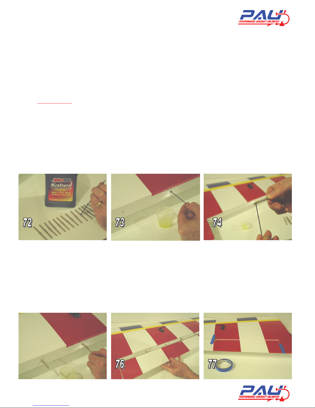
9. Now were going to prep the hinges for installation. Take a small drop of oil and place it in each of
the pivot points of your hinges. The oil prevents excess epoxy from bonding the joint (figure 72).
10. Working with one panel and control surface at a time, apply epoxy into the hinge holes of the
trailing edge. Apply epoxy to one side of the hinges and insert them into the holes (figure 73, 74, and
75).
11. Apply epoxy into the leading edge holes of the control surface and the other side of the hinges.
12. Carefully insert the control surface into the hinges and butt the two surfaces together. Move the
surface up and down a couple of times to make sure all the hinges are aligned correctly and the desired
throw is attained. 35 degrees for ailerons and 45 degrees for all others (figure 76).
13. Use some masking tape to hold the surfaces together and let cure for at least eight hours. Repeat
these steps until all of the surfaces are epoxied in place (figure 77).
Property of Performance Aircraft Unlimited
Property of performance Aircraft Unlimited 13
14. Install the tiller springs you set aside in chapter 2 to the tiller horn and tiller.
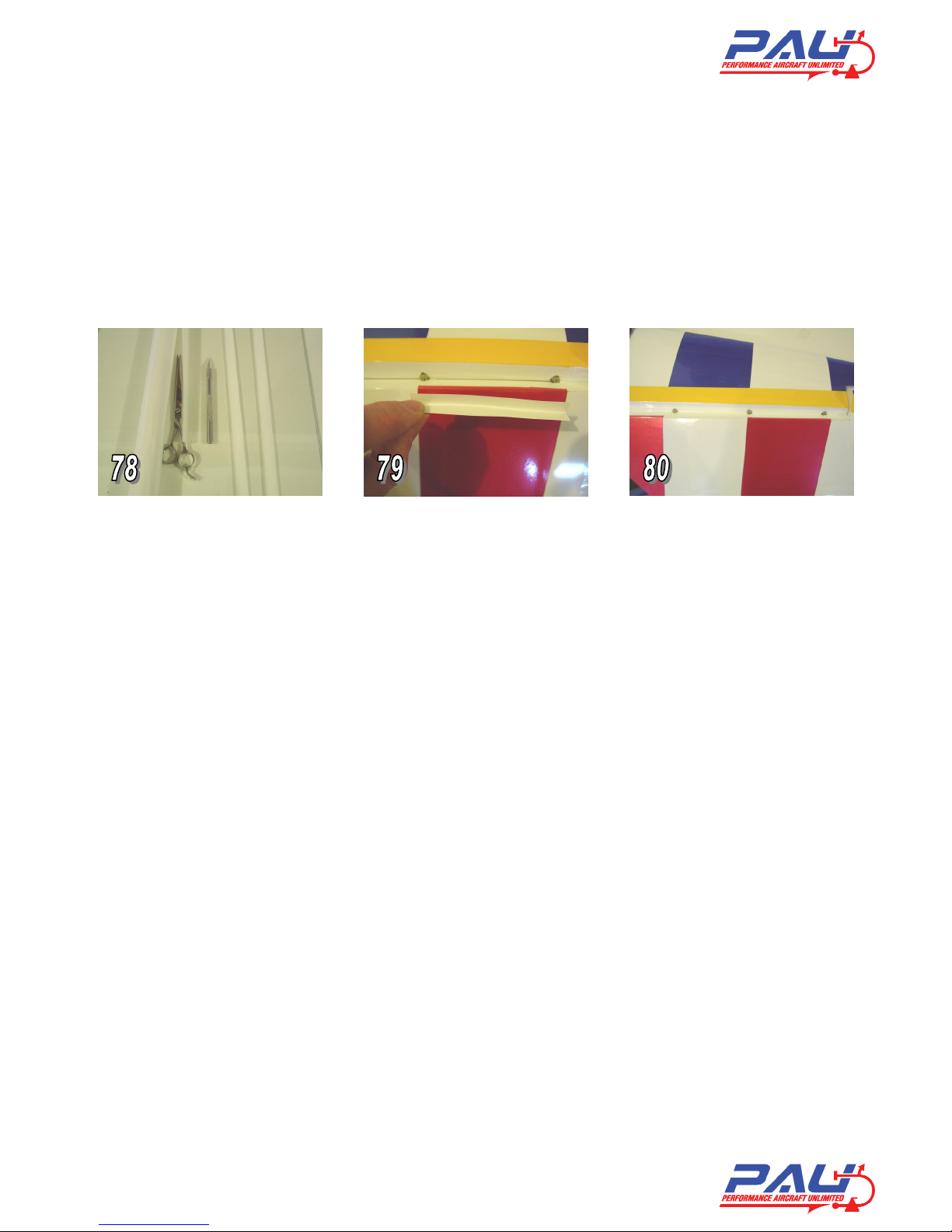
Tip#4 Optional step. After your epoxy has cured, it would be a good time to seal all of your hinge gaps prior to
installing you hardware. This can provide you with a better flying aircraft by increasing control surface
performance and preventing possible flutter. Clear or matching covering material can be ironed in place to fill
any gaps on the bottom of your control surfaces.
Take approximately a one-inch strip of covering the length of your surface. Fold it in half while placing into
the gap with the control surface fully deflected up and iron it in place. Check to make sure you still have full
surface travel once you have completed (figure 78,79, and 80).
Tip#5 Optional step. After your epoxy has cured, it would be a good time to seal all of your hinge gaps prior
to installing the rest of the hardware. This can provide you with a better flying aircraft by increasing control
surface performance and preventing possible flutter. Clear or matching covering material can be ironed in
place to fill any gaps on the bottom of your control surfaces.
Take approximately a one-inch strip of covering the length of your surface. Fold it in half while placing into
the gap with the control surface fully deflected up and iron it in place. Check to make sure you still have full
surface travel once you have completed.

Property of Performance Aircraft Unlimited
Property of performance Aircraft Unlimited 14
Chapter 8
Hardware Installation
We provide high quality aluminum control horn assemblies included with our latest generation of PAU aircraft
kits. We believe these lightweight assemblies are the best available and can also be purchased separately from
PAU. Many pictures in this section are that of our Sukhoi as the assembly in this section is identical to the PAU
Extra 300SP
Place an “×
××
×” to ensure task completion:
What you will need in this chapter:
The entire airframe
Four titanium push rods
Six sets of aluminum control horn assemblies
Four steel posts
Six HD Dubro ball links
One 20oz Du-bro fuel tank
Not Provided:
Two 250oz or better servos for ailerons
Two 200oz or better servos for elevators
One servo for rudder at least 250oz (300oz or
more preferred
One throttle servo 70oz or better
Four 1.5” aluminum servo arms
One 4” offset rudder servo arm
One Fuel dot or other fueling device
Some foam rubber for mounting receiver, ignition module, and fuel tank
Install 250oz or better servos for the ailerons in the servo trays located in the bottom of the wings.
Install 200oz or better servos for the elevators in the servo trays located in the bottom of the horizontal
stabilizers.
Install one or two equaling 250oz or better servos for the rudder in the servo tray inside the fuselage.
Install your throttle and or choke servos.
First you need to find the pre-drilled holes for the steel posts. Install the aluminum control horn
assemblies to each surface with the M4 bolt in the down position. You must blue loc-tite on the
aluminum cone shaped base to ensure the bolt does not try to back out under vibration. Screw on the
horns on to the posts. Do not use loc-tite installing the horn.

Property of Performance Aircraft Unlimited
Property of performance Aircraft Unlimited 15
Make sure your elevator servos are centered and mount your servo arms at 90 degrees to the hinge line.
Take some masking tape and tape the elevator counter
balances to the stabilizers so that they are in a center position.
Screw in your two HD ball links onto the counterclockwise
ends of the push rods and screw the other end into the control
horn. Ensure everything is still centered. Don’t forget to add
locknuts to the 4/40 bolts attaching the ball link to the arm.
Ensure aileron servos are centered and mount your arms
parallel to the hinge line.
Screw in four HD ball links onto the counterclockwise ends
of the 3” H9 push rods and screw the other end into the
control horn. Ensure everything is still centered. Don’t
forget to add locknuts to the 4/40 bolts attaching the ball
links to the arms.
Ensure your rudder servo is centered and mount your rudder
servo arm.
Install your pull-pull cable your remaining pull-pull
hardware. Cables should be crossed to avoid any excess
rubbing on the exits. It is normal for the non-pulling side of
the cable to slacken a little when the rudder is deflected.
Install your tiller springs you set aside earlier.
Assemble the fuel tank according to the directions provided
on the package. You will need to decide whether you want a
two or three-line setup. With a two-line setup you will need
an additional “T” fitting in the carburetor line that connects
to your fuel dot or fueling device. Make sure you use Tygon
fuel tubing inside the tank for the clunk as well.
Install the fuel tank just in front of the wing tube using zip-
ties or hook and latch (Velcro) straps. Place a loop in the
vent line over the top of the tank to prevent fuel loss during
flight and improve flight times. Take small zip-ties or fuel
line clamps and fasten to all the points where the fuels lines
connect.

Property of Performance Aircraft Unlimited
Property of performance Aircraft Unlimited 16
Mount your battery switches in the side of the fuse. We mounted our switches on the black strip of the
fuse thus hiding them from view.
Install the fuel-filling device in a location of your choice. In this case, we installed it just behind the
ignition switch.
Install your throttle push rod. Again as mentioned earlier, we do not want metal-to-metal contact at the
attachment point on the engine. Use a 4/40-rod
with a 2/56 ball link for 4/40 rod to attach the
push rod to the motor.
Once satisfied with your throttle setup, mount
the cowl using the four 6/32 bolts provided and
attach the prop and spinner.
Install the horizontal stabilizers at this time.
Install the carbon fiber stabilizer tube. Slide in
each half and secure them with the four 6/32
retention bolts and washers. On some kits, the
stab tube is approximately ¼” too long. You
may need to trim down your stab tube for proper
fit.
Lets install the wings at this time and check our center of gravity (CG). Install the carbon fiber wing
tube. Slide in each wing panel and secure them with the four nylon wing retention bolts.
Tip#8 For added protection in case the wing retention bolts back out during flight; you can add hitch pins to
the anti-rotation pins of the wing. With the wings installed, mark the anti-rotation pins ¼ inch from the
fuselage side. Remove the wings and drill a small hole in the anti-rotation pins. You can find appropriate
sized hitch pins at most local hardware stores. Re-install wings and insert the hitch pins for added
protection.
Now we’re ready to check the CG and install your remaining hardware. The CG range is 5 to 6 inches back as
measured where the wing meets the fuselage. We recommend 5.5 or center on the wing tube for all types of
flying.
Check CG at this time and place your batteries and remaining hardware in locations to attain the desired
CG. If satisfied mount your remaining hardware.

Property of Performance Aircraft Unlimited
Property of performance Aircraft Unlimited 17
Congratulations! You have just completed assembly of your Edge 540T.
Chapter 9
Radio and Control Surface Setup
Now we are ready to setup your aircraft for flying. Included is this manual are templates for measuring surface
throw you may use if desired. We recommend that you setup your aircraft on low rates for initial flights until
you become familiar with the aircraft and its capabilities.
The recommended low rates for this aircraft are:
25 degrees for ailerons with 0 to 20% expo
15 degrees for elevators with 0 to 20% expo
30 degrees for rudder with 0 to 20% expo
The recommended high rates for this aircraft are:
35 degrees for ailerons with 40 to 70% expo
45 degrees for elevators with 40 to 70% expo
45 degrees for rudder with 30 to 70% expo
or as much as you can stand for hardcore flyers.
CG Range is 5 to 6 inches.
Place an “×
××
×” to ensure task completion:
What you will need in this chapter:
Completed airframe
Radio
Throw templates or meter
Cut out the templates for surface throw. These should be located on the last page of this manual.
Tape each one in place using the horizontal line as a reference point to each stabilizer at the counter
balance and at the inside of the wings where the ailerons meet.
Set your throws accordingly. Double check to make sure nothing is binding to include the throttle and
or choke servos and their linkages. Also, ensure all surfaces and controls are moving in the proper
directions.

Property of Performance Aircraft Unlimited
Property of performance Aircraft Unlimited 18
Chapter 10
Final Inspection and Pre-Flight
Welcome to the final chapter prior to your maiden flight. We hope you have enjoyed building your Edge 540T.
Lets go over the airframe and perform a pre-flight to make sure everything is in order.
Inspect the airframe for any visible damage and loose covering that may have occurred during the build.
Inspect the main landing gear and tail wheel assembly. Ensure all mounting hardware and collars are
fastened properly.
Inspect your motor installation and cowl to ensure all bolts are tight and the muffler is firmly mounted in
place. Check the motor and muffler for possible contact with the cowl. Inspect ignition module and
spark plug wire for proper mounting. Check propeller and spinner to ensure they are both secure.
Inspect the inside of the fuselage to ensure your batteries, switches, regulators (if equipped), fuel tank
and lines are securely fastened. Check nylon wing bolts to ensure they are in place and secured.
Inspect all control surfaces and control surface hardware. Gently tug on each surface to make sure the
hinges are properly bonded. Check the four 4/40 horizontal stabilizer fasteners and ensure they’re in
place and secured.
Check all servos for mounting screws. Check servo arm mounting screws and inspect that the 4/40 links
have been secured with lock nuts.
Fill fuel tank and inspect for any leaks.
Check your batteries in both your aircraft and radio to ensure they are fully charged
Turn on radio to inspect all controls for binding, proper direction and throw while on high rates.
Re-check CG. It should be anywhere from 5 to 6 inches depending on your flying style.
Secure aircraft using a buddy or hold down and start motor according to manufacturers guidelines.
Don’t forget to lower your throttle prior to ignition.
Perform a proper range check with the motor running using your radio manufacturers instructions.
Make sure you go back to low rates for your maiden takeoff and enjoy!
This concludes your pre-flight checks. After your maiden flight, repeat these steps to perform a post flight to
ensure nothing has loosened. It’s always a good habit to use a checklist like this one to go over your aircraft
prior to the first flight of the day.

Property of Performance Aircraft Unlimited
Property of performance Aircraft Unlimited 19
Flying!
Many hours went into developing this Edge 540T keeping the scale appearance while still having unbelievable
flight performance. For contest flying such as IMAC or 3d, the CG at 5.5” or the center of the wing tube offers
great precision and 3d performance.
Every airplane has structural limits, and the larger the plane is, the more critical it is to understand and
respect these limits. This is particularly true for 3D aerobatic planes, since by design, these planes are light
weight, over powered, and have oversized control surfaces.
Pilots need to use proper throttle management, and avoid high speed when executing high stress maneuvers
such as Walls, Parachutes and Blenders. As a general rule, the throttle must be at idle position whenever the
nose is pointed down (whether at 90 degrees or 45 degrees down line).
Planes must be inspected frequently, looking for any loosening screws, bolts and glue joints. Servos and
linkages must be free of play or “slop”, as this is a major cause of flutter (and crashes).
Understanding and applying these few safety and maintenance guidelines will help you get many enjoyable and
rewarding flights with your Giant Scale Plane.
We hope this aircraft offers you many years of enjoyment. Thank you again for choosing PAU and look for
exciting future products.
Additional products from PAU:
100, and 150cc Edge 540
50, 100, and 150cc Edge 540T.
50, 100, and 150cc Extra 300sp.
40 to 50cc Pitts Challenger and Bulldog.
100cc Ultimate.
50cc Sukhoi

Property of Performance Aircraft Unlimited
Property of performance Aircraft Unlimited 20
DA-50 Template
If printing from Adobe, turn off page scaling.
Table of contents
Other PAU Toy manuals


Popular Toy manuals by other brands


krakpol
krakpol leomark 102/246258 Assembly instruction

Fisher-Price
Fisher-Price Sparkling Symphony Starlights Bear quick guide

Innovation First
Innovation First VEX IQ Mia Build instructions

Laine's Planes
Laine's Planes Cuda manual

LeapFrog
LeapFrog Twist & Shout Parent guide & instructions

REVELL
REVELL Hawker Fury Mk.I Assembly manual