PAU Extra 300SP User manual

60” Extra 300SP ARF Instruction Manual
Congratulations and thank you for purchasing the Performance Aircraft Unlimited 60 inch Extra
300SP. The Extra is arguably one of the most renowned aerobatic aircraft ever produced.
Walter Extra who originally designed the Extra, named his aircraft by the horsepower rating of
the motor placed in them. The Extra 300SP is one of the newest releases in full scale and now
R/C.

Our aircraft was designed with 655 sq inches of wing area while keeping the total weight to a
minimum. Whether you want an aircraft precise enough to compete in IMAC or 3D until you’re
airsick, the PAU Extra fits the bill. Its light weight gives you the stability in high-alpha to take it to
the extremes of the flight envelope. If tumbling maneuvers are your thing, our Extra 300sp will
deliver with picture perfect waterfalls and blistering tip spins that are not for the faint of heart.
We believe you will find this to be one of the finest flying aircraft on the market. Most modelers
will find assembly of this aircraft simple and straightforward. We recommend the builder follow
the step-by-step instructions to achieve the best performance and to ensure nothing was over
looked. This manual also includes tip sections throughout that may help you in key areas during
assembly. Please familiarize yourself with this manual before assembly.
This manual is broken down into ten chapters for simplicity:
Chapter 1 - Parts Inventory
Chapter 2 - Preparation for Assembly
Chapter 3 - Landing Gear
Chapter 4 – Motor and ESC Installation
Chapter 5 - Cowling installation
Chapter 6 - Rudder and Elevator Installation
Chapter 7 – Wing Assembly
Chapter 8 - Radio and Control Surface Setup
Chapter 9 - Final Inspection and Pre-Flight
Additional items needed to complete this aircraft, which are not included:
A motor and esc, within the recommend range, and propeller
6 channel computer radio and receiver recommended
Batteries
Two aileron servos rated at least at 70oz of torque
One elevator servos rated at least at 70oz of torque
One rudder servos rated at least at 70oz of torque
5 to 15 minute epoxy

A bottle of thin CA
Covering iron
Various modeling tools for assembly
Chapter 1
Parts inventory
Place an “” to ensure your kit is complete:
1 Fuselage
2 Wing panels (1 right and 1 left)
1 Horizontal stabilizers
1 Rudder
1 Fiberglass Cowl
1 Pair of fiberglass wheel pants
1 Main landing gear
1 Pair of Light wheels
1 Tail wheel and tiller assembly
1 Canopy
1 Carbon fiber wing tube
4 pushrods/turnbuckles
1 set of wheel collars
1 pair of wheel axles
1 Set of control horn assemblies
8 ball links
1 Vinyl graphics package
If any of these parts are missing immediately contact PAU.

Chapter 2
Preparation for Assembly
Professionals utilizing premium Ultracote covering carefully covered your model. Due to
climate changes during shipping, the models covering may have loosened and/or
winkled. It’s a good habit to go over your model with a covering iron to ensure all joints,
seams, and edges are properly sealed.
Ultracote is a lower temperature film that seals and shrinks at lower temperatures.
Make sure you set your iron on a low temperature initially to get a feel for the correct
temperature setting and adjust accordingly. Higher temperatures will cause your
covering to over shrink and distort. Also, use a sock over your iron to ensure a scratch
free finish.
Place an “” to ensure task completion:
Go over you model as necessary with a covering iron to insure all joints, seams, and
corners are sealed properly.
Use your iron to ensure the areas where cutouts are needed for your hardware are
located and sealed down, such as servos; tubes, and control horn mounting locations.
Chapter 3 Landing
Gear and Tail Wheel Assemblies
Now that we’re ready for assembly, we are going to start with the main landing gear
first. You will need to locate the following parts to begin assembly.
Place an “x” to ensure task completion:

What you will need in this chapter for the main gear:
Main gear
One pair of wheels
One pair of wheel pants
One pair of wheel pant cuffs
One pair of axles
Two wheel collars
Nylon spacers
Fuselage
Tail wheel assembly
Slide wheel cuffs onto the main gear.
Insert nylon spacer onto wheel axel, then wheel.
When putting collars on make sure the wheel can
rotate freely. We also recommend using lock-tite
on set screws to prevent collars from becoming
loose.
Insert wheel axel onto main gear, on the back size use supplied washer and nut. Only
thread in the nut until wheel pant in slipped between the axel and main gear. Once
wheel pant is properly aligned tighten down nut while holding axel.
Install landing gear on fuselage using the supplied 3mm screws and washers.
With the main gear on, it is time to set the landing gear cuffs. First, cut a slit along the
neoprene tubing and slide the tubing onto the top edge of the gear cuffs, where the
cuffs will meet the fuselage.
Next, take some Goop glue and apply it to the landing gear where the bottom of the
cuffs meet the gear.

Slide the cuffs up against the fuselage and use tape to hold them in place while the
glue sets. Don’t set the cuffs too tight against the fuselage, as the gear needs some
room to flex without cracking the cuffs.
Chapter 4
Motor and ESC Installation
Your firewall come pre drilled and ready to use with 4020 size motors. We recommend
the PAU 4020 540KV motor (made by Scorpion) along with the Castle Talon 90 amp
ESC.
Install motor onto the firewall using supplied 3mm screws.
Mount ESC on the side of the firewall to ensure ESC gets proper airflow and cooling.
Make sure to test motor direction

Chapter 5
Cowling installation
Begin by cutting a piece of paper and tacking it over the two mounting tabs on the
fuselage, using a marker or pencil make a dot on the middle of the mounting tab.
Slip cowl on under the pieces of paper, using the spinner backplate align cowl to
match spinner and have proper clearance.
Once satisfied with cowl placement drill a hole where the dot you previously is. After
drilling the hole procced to install screws to help hold cowl and prevent it from moving.
Chapter 6
Rudder and Elevator Installation
Slip elevator upside down and backwards
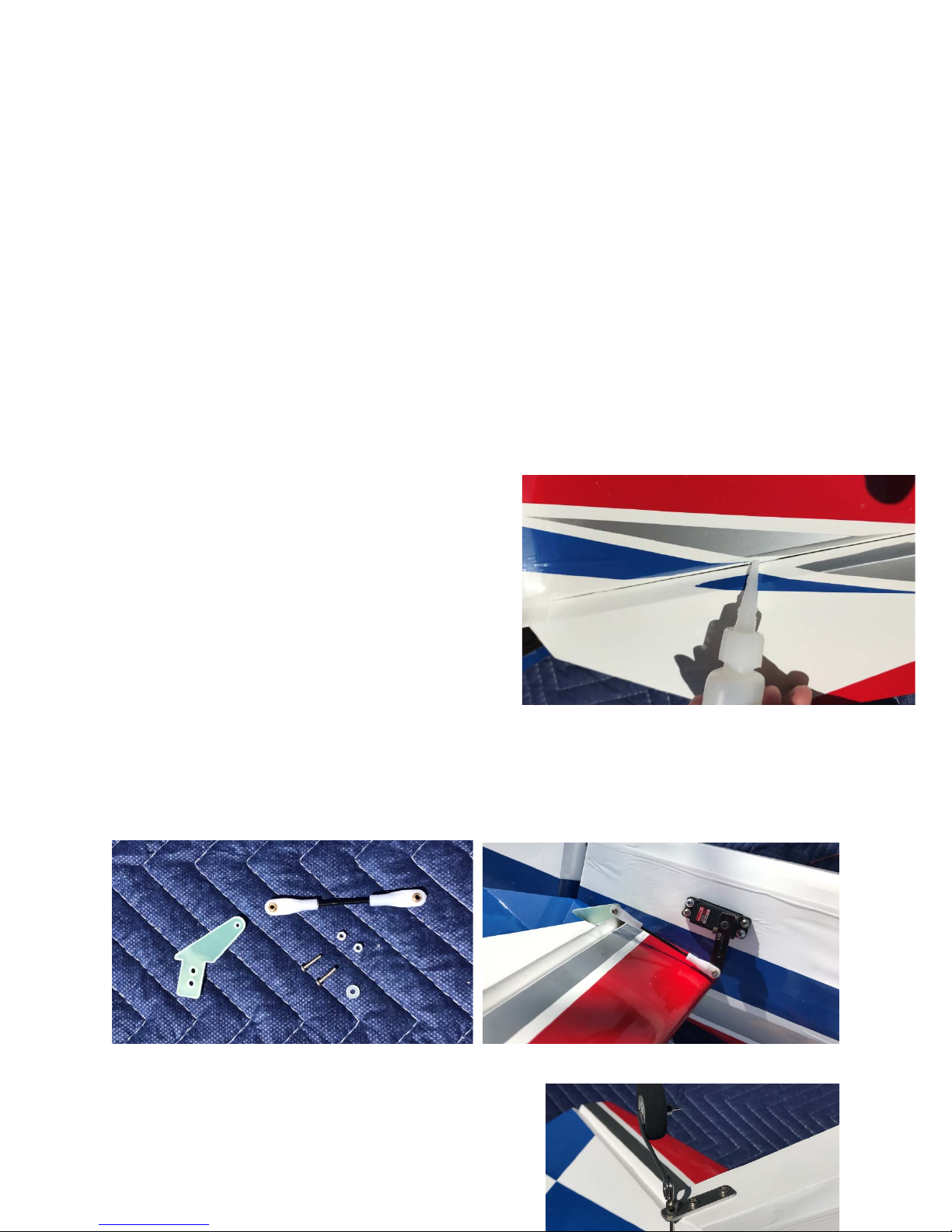
through the horizontal stabilizer slot in the
fuselage. Once elevator is in you can now
install the horizontal stabilizer using thin CA.
Make sure horizontal stabilizer is properly
aligned before using any glue.
Next insert elevator onto the provided CA
hinges. Glue hinges using thin CA and carefully
dripping the glue on top of hinge on both sides.
Before gluing in the control horn, make sure to properly sand the portion that goes
into the wood. After sanding, test fit and glue with 5-15 minute epoxy. Make sure control
horn in completely in the surface.
Once glue has dried you can install the elevator servo and linkage.
Install the tail wheel with supplied screws.

Make sure to align the tail wheel assembly
with the sharpest point of the bevel to ensure
it doesn’t put extra stress on the rudder.
Install rudder the same way as the elevator,
Using CA hinges and thin CA to soak the hinge.
Make sure to place the hook for the tail wheel
assembly before gluing the rudder.
Follow the same steps to install the rudder
servo as the elevator servo.
Chapter 7
Wing Assembly
Install ailerons using CA hinges. Using thin CA, carefully drip CA onto the hinge on
both top and bottom to ensure a proper bond to the wood.
Before installing the control horn, sand the portion that will be glued into the wood.
Use 5-15 minute epoxy to glue in horn making sure that it is completely inside the
surface.
Install servos and linkage.

Chapter 8
Radio and Control Surface Setup
Now we are ready to setup your aircraft for flying. We recommend that you setup your
aircraft on low rates for initial flights until you become familiar with the aircraft and its
capabilities.
The recommended low rates for this aircraft are:
20 degrees for ailerons with 0 to 20% expo
12 degrees for elevators with 0 to 20% expo
30 degrees for rudder with 0 to 20% expo
The recommended high rates for this aircraft are:
35 degrees for ailerons with 40 to 70% expo
45 degrees for elevators with 40 to 70% expo
45 degrees for rudder with 30 to 70% expo
…or as much as you can stand for hardcore flyers!
Place an “x” to ensure task completion:
What you will need in this chapter:

Completed airframe
Radio
Throw templates or meter
Set your throws accordingly. Double check to make sure all surfaces are moving in
the correct directions.
Chapter 9
Final Inspection and Pre-Flight
Welcome to the final chapter prior to your maiden flight! We hope you have enjoyed
building your Extra.
Let’s go over the airframe and perform a pre-flight to make sure everything is in order.
Inspect the airframe for any visible damage and loose covering that may have
occurred during the build.
Inspect the main landing gear and tail wheel assembly. Ensure all mounting
hardware and collars are fastened properly.
Inspect your motor installation and cowl.Check the motor for possible contact with
cowl. Check propeller and spinner to ensure they are both secure.
Inspect the inside of the fuselage to ensure your battery, receiver and wing bolts are
secured.
Inspect all control surfaces and control surface hardware. Gently tug on each surface
to make sure the hinges are properly bonded.
Check all servos for mounting screws. Check servo arm mounting screws.
Make sure battery is fully charged
Turn on radio to inspect all controls for binding, proper direction and throw while on
high rates.
Re-check CG. It should not be behind the wing tube for initial flights.
.
Perform a proper range check with the engine running, using your radio
manufacturer’s instructions.
Make sure you set low rates for your maiden takeoff and enjoy!
This concludes your pre-flight checks. After your maiden flight, repeat these steps to
perform a post flight to ensure nothing has loosened. It’s always a good habit to use a
checklist like this one to go over your aircraft prior to the first flight of the day.
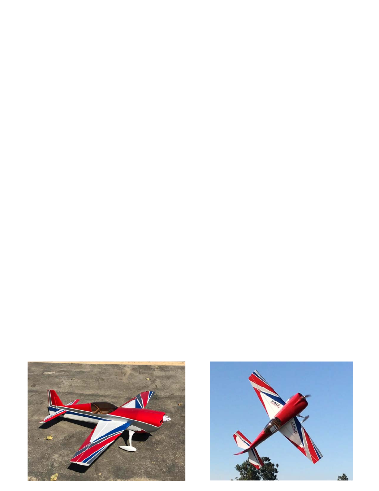
Flying!
We believe you will find this aircraft finest aircraft you’ve ever flown. High-alpha stability
gives you solid control and confidence to bring it right down on the deck! For contest
flying such as IMAC, a CG on the wing tube offers great precision and little coupling.

We hope this aircraft offers you many years of enjoyment. Thank you again for
choosing PAU and look for exciting future products.
Additional products from PAU here: https://www.flypau.com/
Table of contents
Other PAU Toy manuals


Popular Toy manuals by other brands


Smoby
Smoby 99511791F quick start guide

GREAT PLANES
GREAT PLANES Gitabria instruction manual

Our Generation
Our Generation OG Cooking Island instructions

Hangar 9
Hangar 9 Timber 110 30-50cc instruction manual

MOOSE
MOOSE BEST LAB BIO MIST & EXPERIMENT REFILL PACK instruction manual

Rail King
Rail King USRA 0-6-0 Steam Engine Operator's manual

Bandits and Angels
Bandits and Angels TWT8376 Assembly instructions

RESTORATION GAMES
RESTORATION GAMES Return to DARKTOWER REO9200 quick start guide

GREAT PLANES
GREAT PLANES Gee Bee instruction manual

FLIGHT DESIGN
FLIGHT DESIGN CT2K Parts and assembly manual

Hasbro
Hasbro Spiderman 3 Venom Trap 69102 instruction manual

RCRCM
RCRCM DLG Ali instruction manual