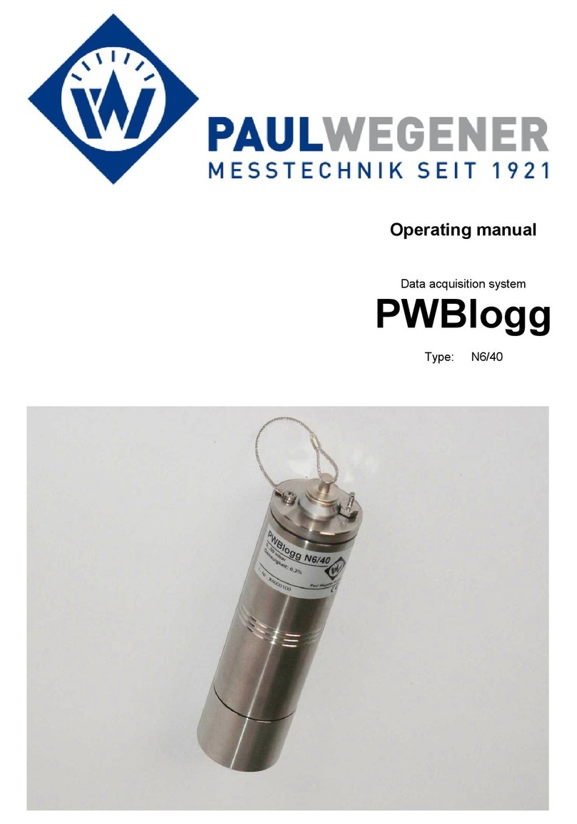
Paul Wegener PWBlogg iModem6 User manual

Operating manual
Data aquisition system
PWBlogg
Device version: iModem

Paul Wegener GmbH
Paul Wegener GmbH
Marienstraße 24
D-06493 Ballenstedt
8. Edition 2022, Editing Date 06/22
© Paul Wegener GmbH, Ballenstedt
All rights reserved. No section of the operating manual may be replicated or processed, duplicated or
distributed using electronic systems in any way (print, photocopy, microlm or other methods) without prior
written permission of the Paul Wegener GmbH.
Design and specications are subject to change without notice.
2

Contents
1 Introduction 4
2 General safety instructions 4
3 Special conditions for use in potentially explosive gas atmospheres of the zone 2 4
4 Special notes on antenna use in Ex zone 2 5
5 Start-up instruction 6
6 Hardware iModem 6
7 Status indication 8
8 Battery change 10
9 Charging the built-in accumulator (optional) 10
10 Technical data 11
11 Transport and storage iModem6 11
12 Recycling batteries and old appliances 11
3
Operating manual of data acquisition system PWBlogg

Paul Wegener GmbH
1 Introduction
The PWB iModem is designed for remote data transmission for PWB-data loggers. Dierent protocols can be
used for data inquiry. The parameterization of the modem is done by the software PWB-Soft.
2 General safety instructions
• This device must only be installed and operated in compliance with the instructions and warning notices
of the dedicated technical documentation.
• Only qualied personnel must install and operate this device.
• The data logger‘s power supply is done by a lithium primary battery. This can optionally be done by a
power supply unit too. In this case the internal lithium battery supplies the data logger during temporary
power failure.
Please note the following safety advice before you install and operate the devices:
• The power supply units and batteries delivered by manufacturer must exclusively be used. Failure to do
so may result in severe damage and accidents.
• Please pay attention to intactness of all connection cables. If there are cable damages, put the device out
of operation immediately. Contact maufacturer for repair.
• Do not charge lithium batteries, throw them into re or expose them to heat, as this can lead to battery
explosion and result in personal injury and/or material damage.
• If uid from battery pack gets into your eyes, rinse them with plenty of water and see a doctor.
• Never use water to extinguish burning batteries! EXPLOSION HAZARD!
• Do not use damaged batteries!
• Do not short-circuit batteries!
4
• Mounting and connecting the device must only be done if there is no potentially explosive atmosphere.
• This device must only be used in areas with pollution level 2 as dened in IEC60991-1.
• This device is only suitable in areas with low risk of mechanical hazards.
• Connecting and disconnecting the plug connectors (antenne too) are only permitted if there is no explo-
sive atmosphere. Operating the moden without antenna is not permitted.
• Unplugged connectors are not permitted in hazardous areas. Always remove unplugged connectors from
hazardous areas!
• Opening the case (e.g. for battery change) must only be done if there is no potentially explosive atmo-
sphere.
• The case must only be cleaned by using wet cloths, otherwise there is the danger of spark ignition by
electrostatic discharge.
• The „online outlet“ for data transmission and data logger conguration must only be used in case of no-
nexistence of an explosive atmosphere. If not used, the „online outlet“ must be closed with the dedicated
cap.
• If the online outlet is permanently used, make sure that the connected devices are with voltage rating no
more than 60V AC or 75V DC. Furthermore make sure that there is a transient protection and that it is set
to a value that does not exceed 140% of the rated voltage.
Attention: The electronics consist of electrostatic sensitive components. Pay attention to ESD-
operation instructions when handling this electronics!
3 Special conditions for use in potentially explosive gas atmospheres of the zone 2

5
4 Special notes on antenna use in Ex zone 2
• The ANT2-M is an antenna which is applicable when using a PWBlogg iModem in zone 2 areas endange-
red by gas explosions.
• Please note: The ANT2-M is classied as „simple apparatus“ as there is no ignition risk just by the anten-
na. Therefore ATEX markings are not permissible.
• The ANT2-M has been assessed together with the PWBlogg iModem to ensure that there is no ignition
risk by interconnecting both.
• If the iModem including a dierent antenna is supposed to be used in areas of the zone 2 endangered by
gas explosions, the antenna must be installed outside any dangerous area or a risk assessment must be
conducted by manufacturer again.
Operating manual of data acquisition system PWBlogg
• If the data logger is supplied by external voltage, the power supply unit delivered by manufacturer must
exclusively be used. This is always connected with the supply voltage outside of the explosion-hazard
area. Use the power supply unit only at the intended supply voltage. Supplying the data logger using
dierent power supply units and additional equipment is not permitted.
• If the device is equipped with a lithium ion battery, charging this battery must be done outside the poten-
tially explosive areas.
• For integration into the system‘s potential equalization use the dedicated port at the data logger‘s case.
Note: The data logger‘s battery circuit is operatively grounded at its case.
Any subsequent modication to the device results in the consequence that a secure use is no more
guaranteed within ex-zone 2 and the EC declaration of conformity loses ist validity.

Paul Wegener GmbH
6
5 Start-up instruction
Please, consider following references during initial operation of the modem:
• Initially, install the software PWB-Soft
• Connect the iModem to power supply
• Then connect the iModem to PC by means of data cable for online-connection.
• Start the PWB-Soft.
• Adjust the interface in the dialog box „Connect“.
• Open “iModem” dialog in the menu “Module”
• Click on the „Connect“ button.
• When the connect dialog appears, adjust in the iModem eld to „automatic“.
• Connect the modem to the PC/laptop.
• To open the iModem dialog, click on the modem number in the main dialog.
• Click on the button „conguration“.
• Carry out all necessary settings. After conrming via „transmit“, the iModem will be congured again.
• Before you insert the SIM card, enter the correct PIN number to avoid disabling the card.
6 Hardware iModem
The iModem is delivered in aluminium-form housing with degree of protection IP 65. A xed online cable
provides connection to a data logger. Depending on online port type at the data logger, an infrared or R232
interface is provided. PC connection to data logger and iModem is done via online port of the iModem. A
correct power supply must be provided for connection to a data logger or to an iModem respectively. For this
purpose, there are dierent options provided.
1. Battery:
The modem can be equipped both for bypassing power failure periods and for power supply only. The battery
BP16.5N5L is provided as standard since version iModem5 was introduced. This type supplies necessary
operating current for GSM/GPRS connection and has no eect of passivation. The iModems as of generation
5 have built-in SuperCaps. The data logger battery type BP16.5N5 is used in this case too.
2. External voltage:
Depending on type, the modem can be supplied with external voltage between 12 and 14 volt. Normally, the
device is operated by a 12 V mains adapter. Combined with a lithium battery, an uninterruptible supply can be
ensured. A backup battery, however, ist not necessary for operating the modem. Any parameter, necessary
for operation, is saved in non-volatile memories. Date and time are taken from connected data logger.
3. Accumulator:
Power supply for mobile applications is also possible by accumulator (separate manual).
The reasonable adjustment of time slots allows economical operation of devices and long battery life. On
request, a life estimation will be made by the Paul Wegener GmbH.

7
The previous gures show the iModem with lithium battery to supply it. Before operating the GSM modem,
the correct PIN number of the SIM card must be adjusted via iModem-software!
The online-connection is on the right. It is used for connection to the integrated or external data logger or ELS
and for making the iModem settings. The antenna is located above at a GSM modem.
Before connecting GSM modem, the SIM card must be inserted into the modem. For that purpose, on iMo-
dem3, you must open the cover of modem-housing. The SIM card slot is located on the GSM module and
can be opened at an eject button using a small pointed item. The iModem4 provides the SIM card slot under
the battery holder. Please insert the SIM card as shown in the photo. After the SIM card has been inserted,
the modem can be closed again and is ready for operation.
Operating manual of data acquisition system PWBlogg

Paul Wegener GmbH
8
7 Status indication
Status LED Modem LED
Status LED (green):
The status LED of the iModem ashes in dierent frequencies or is permanently illuminated to indicate the
current status of the iModem processor.
If the online cable is plugged, the permanent activated status LED indicates that the modem processor is
ready to receive commands from PC/laptop. If the online cable is plugged and the LED ashes, that means
the iModem is performing a task (data transmission, modem initialisation etc.) and not ready-to-receive!
Flashing in 2,5s pulse: The iModem has recognized the connected data logger. The processor is at sleep
mode.
Flashing in 1s pulse: The iModem has not recognized the connected data logger or no data logger is connec-
ted. The modem searches every 30s for the logger.
Quickly ashing in 0,25 pulse: The processor of the iModem is busy (eg searching/reading the logger, sen-
ding SMS etc.)
Flashing in 0,5s pulse: The iModem has recognized a call or established connection to a receiver. Online is
not possible now.
Modem LED (red):
Status display of the modem:
This LED is o when the modem module is deactivated. As long as modem LED is o, no SMS can be sent
and no call can be answered.
A slowly ashing LED (iModem4/iModem5) indicates the modem is activated, but no call is active.
If an iModem6 is activated, the LED is permanently illuminated.
Quickly ashing LED (iModem4/iModem5): A call has been recognized and connection is established.
LED permanently on: The modem is activated, but still has no connection to mobile service provider.
If the LED illuminates permanantly only for some seconds, turns o and illuminates permanantly later again,
faulty settings might make errors when initializing the modem. Hence the modem can not be activated and
will be switched o after 5 failed attempts.

9
Operating manual of data acquisition system PWBlogg
The following applies to iModem4/iModem5:
If the LED illuminates permanently, problems on reception are indicated.
After initializing the modem, shortly ashing LED and switching o again indicates that faulty GPRS parame-
ters may inhibit successful initialization.
If, after modem activating, the LED illuminates 2s and turns o again, then a wrong PIN or a disabled SIM
card can stop initialization!
Assistance on knowing problems:
1. The modem does not activate itself:
• examine ashing behaviour of the modem LED of the modem
• check power supply (power supply unit/battery)
• check PIN of the SIM card
• check reception
• check time slot
• make sure that the data logger is connected (modem adopts time from logger)
2. SMS‘s are not sent:
• check, whether the respective event is activated and a receiver is specied (activating SMS or alert SMS),
• the modem will be activated,
• a PC is connected, which inhibits communication to the modem,
• when using N7 data loggers: check, whether the event “send SMS” is specied as alarm event,
• whether power supply is ok,
• whether the SIM card is unlocked (PIN OK or deactivated)
3. The modem can not be called:
• check, whether a time slot is specied and the modem is activated,
• the right call nummer is used (data call number)
• the SIM card is eligible for data calls,
• a PC is connected to the modem which blocks calls,
• the modem of the receiver is eligible for calls and its settings have been properly made
4. The modem does not write into the web database:
• check, whether the modem is specied as GPRS modem,
• the dedicated rmware is used,
• GPRS parameters are correct,
• FTP transfer is activated (time slot 15min or 1h)
5. The modem does not send data mail:
• check, whether correct SMTP parameters are specied,
• GPRS parameters are correct,
• the modem is specied as GPRS modem,
• a mail address is entered as receiver (eg event time slot)
The iModem4/iModem5/iModem6 provide the status LED (green) and modem LED (red) on the housing co-
ver to make them visible without opening the device.

Paul Wegener GmbH
10
9 Charging the built-in accumulator (optional)
• Do solely use the delivered original charger for charging the accumulator.
• Make sure that the charger‘s specied input voltgage agrees with the local supply voltage.
• The used power socket must be accessible during the whole charging process.
• While charging, the temperature must be betwen +10°C and +45°C.
• The status LED‘s at the charger indicate the state (red = charging, green = charging nished) during char-
ging process.
• An entirely discharged accumulator needs about 3h charging time.
• The PC software PWB-Soft provides information on the residual accumulator capacity.
• To preserve the accumulator, you should switch o the moden when it is not used for long. You ideally
store the modem with residual capacity of about 20%, but never with discharged accumulator.
Note: Depth discharge leads to permanent damage of the accumulator!
If the accumulator‘s residual capacity falls below 20%, it should be charged. We recommend 100% charge
before any use.
The accumulator must not be changed by the user. If a new one is necessary, forward the device to manu-
facturer.
8 Battery change
We recommend battery change should be done by manufacturer. If you change battery by yourself,
please not following procedure:
• A respective battery type including plug connector is available by manufacturer.
• Loose the four fastening cross-head screws of the cover plate.
• Loose carefully the plug connector of the battery and remov the old battery.
• Put the new battery in and press it on the dedicated Velcro pad (iModem3, iModem5, iModem6).
• Connect the new battery to the plug connector of the modem.
• Close the housing again without crushing connecting cables.
No data or parameters get lost when changing battery. After battery change, the modem will contact the log-
ger for the purpose of time synchronization.

11
11 Transport and storage iModem6
It is recommended to remove the battery from the dedicated pin-and-socket connector for transport and sto-
rage of the iModem6.
To reset the iModem, the battery must be plugged again. Note: the SuperCap can be partially discharged
after a long storage period. Meanwhile individual modem features are available to a limited extent only (in
particular for data transmission).
12 Recycling batteries and old appliances
Used electric appliances, batteries and rechargeable batteries are subject to particular statutory
provisions. Batteries, rechargeable batteries and electric appliances must not be disposed with
the household waste.
The end user is obligated to return them by the law. Used electric appliances, batteries and re-
chargeable batteries can be disposed at collecting points, municipal disposal areas or by manu-
facturer / supplier.
The Paul Wegener GmbH as seller of batteries and electric appliances fullls its take-back obligation and
disposes used batteries and old electric appliances free of charge.
This take-back obligation, however, limits itself to used electric appliances, batteries and rechargeable batte-
ries which belong or belonged to the product range of the Paul Wegener GmbH and the amount which was
delivered by the Paul Wegener GmbH.
The end user bears the forwarding charges.
Operating manual of data acquisition system PWBlogg
10 Technical data
• Housing: aluminium cast 80 x 160 x 60 mm (w x h x d)
• Degree of protection: IP65
• Weight: approx. 1400 g
• Power suppy : lithium battery 16,5 Ah (optional external supply 12 VDC)
• Operation time: up to 3 years
• Data transmission: RS232 or infrared
• Explosion protection: II 3G Ex ec IIC T4 Gc X (optional)
• Ambience: -20°C ≤Ta ≤ 60°C
pollution degree 2

EU
EU
EU-DECLARATION OF CONFORMITY
Product description:
PWBlogg iModem
The specied product is in compliance with following European directives.
2014/30/EU electromagnetic compatibility
2014/34/EU equipment and protective systems intended for use in potentially explosive
atmospheres
2014/53/EU radio equipment directive (RED)
and has been developed and tested using the following standards:
EN 61000-6-3:2011-09 subject basic standard for emitted interference – emitted interference for living
quarters, business- and trade as well as small rms
EN 61000-6-2:2011-06 subject standard for interference resistance– industrial sector
EN 60079-0:2019-09 electrical equipment for explosion-hazard areas, section 0: general requirements
EN 60079-7:2016-08 explosion-hazard areas, section 7: equipment protection by increased safety „e“
Marking as category 3 - equipment for use in explosion-hazard areas of the zone 2:
II3G Ex ec IIC T4 Gc X
Manufacturer: Paul Wegener GmbH
Marienstraße 24
D-06493 Ballenstedt
Tel.: +49(0)39483 96 300
Fax.: +49(0)39483 96 400
Internet: www.paul-wegener.de
e-mail: info@paul-wegener.de
The safety advice of the product documentation must be followed!
Ballenstedt, 02.06.2022
Wegener
Managing Director
Paul Wegener GmbH
12
-20 °C ≤ Ta ≤ +60 °C

13
Operating manual of data acquisition system PWBlogg

Paul Wegener GmbH
14

15
Operating manual of data acquisition system PWBlogg

Paul Wegener GmbH
16
Paul Wegener GmbH
Marienstraße 24
D-06493 Ballenstedt
Tel.:
Fax:
Internet:
e-mail:
+49 (0) 39483 96 300
+49 (0) 39483 96 400
www.paul-wegener.de
info@paul-wegener.de
PWB FORM 2231-EN22
Most recent amendment: 07.06.2022
Table of contents
Other Paul Wegener Data Logger manuals
