Paytel P6 Series Quick setup guide

Copyright © 2010 Payter..
All rights reserved. No part of this document may be reproduced in any form by print, photo print, microfilm, electronic copy or any other
means without written permission by Payter BV.
P6X Mechanical Integration Guide
Document version : 1.0
Document status : Release
Date : 30-01-2017
Document ID : PTR-40-10-ML-C-0004-01
NOTICE
This manual contains intellectual property, including but not limited, to trade
secrets and know-how, operating procedure and production procedures that
belong solely to Payter B.V.
Disclosure and/or use and/or reproduction of any part of this document strictly
forbidden, except under a written license from Payter B.V.
Payter B.V.
Rozenlaan 115
3051 LP Rotterdam
The Netherlands
P6X Mechanical Integration Guide

P6X Mechanical Integration Guide
Page 2 / 21
Copyright © 2018 PAYTER
BV. All rights reserved. No
part of this document may be
reproduced in any form by
print, photo print, microfilm,
electronic copy or any other
means without written
permission by Payter BV.
Revision History
Rev
Change
Author
1.0
Initial Release
Payter

P6X Mechanical Integration Guide
Page 3 / 21
Copyright © 2018 PAYTER
BV. All rights reserved. No
part of this document may be
reproduced in any form by
print, photo print, microfilm,
electronic copy or any other
means without written
permission by Payter BV.
Abbreviation list
Abbreviation
Description
3G
Third Generation (mobile communication system)
CCI
Coffee Credit Interface
DC
Direct Current
DHCP
Dynamic Host Control Protocol
DNS
Domain Name Server
EDGE
Enhanced Data for GSM (Global System for Mobile communication) Evolution
EMV
Europay Mastercard Visa
EVA
European Vending Association
GPRS
General Packet Radio Service (mobile communication system)
HSPA
High Speed Packet Access (mobile communication system)
IP
Internet Protocol
LAN
Local Area Network
MDB
Multidrop Bus, Communications bus standard for Vending Machines
ms
Miliseconds
PSP
Payment Service Provider
PVP
Payter Vending Protocol
RTP
Remote Terminal Protocol
SAM
Secure Authentication module
SDK
Software Development Kit
SIM
Subscriber Identification Module
USB
Universal Serial Bus
VMC
Vending Machine Controller

P6X Mechanical Integration Guide
Page 4 / 21
Copyright © 2018 PAYTER
BV. All rights reserved. No
part of this document may be
reproduced in any form by
print, photo print, microfilm,
electronic copy or any other
means without written
permission by Payter BV.
Table of Contents
Revision History .............................................................................................. 1
1. Dimensions & Mounting......................................................................... 5
Device opening ................................................................................................................. 5
Mounting options ............................................................................................................. 6
Dimensions P68 The Arc ................................................................................................... 8
Dimensions P66 The Plane................................................................................................ 9
Dimensions The Angle Casing ......................................................................................... 10
Installation P66 Split ....................................................................................................... 11
Dimensions P66S Split Unit............................................................................................. 12
2. Technical Specifications ....................................................................... 13
3. Troubleshooting................................................................................... 14
Result Codes ................................................................................................................... 14
LAN troubleshooting....................................................................................................... 16
Mobile Internet troubleshooting .................................................................................... 18
4. Warnings ............................................................................................. 19
AC Adapter...................................................................................................................... 19
Terminal.......................................................................................................................... 19
5. Contact ................................................................................................ 19
6. Installation Guide................................................................................. 20

P6X Mechanical Integration Guide
Page 5 / 21
Copyright © 2018 PAYTER
BV. All rights reserved. No
part of this document may be
reproduced in any form by
print, photo print, microfilm,
electronic copy or any other
means without written
permission by Payter BV.
1. Dimensions & Mounting
The majority of the Vending Machines have a provision for installing Payment Terminals.
The dimensions of the P6X Terminal series are based upon the EVA (European Vending
Association) standard.
Device opening
Mounting a P6X terminal series requires a device opening that complies to the EVA EPS –
Standard door model measurements (Fig. 19).
Fig. 19 –Dimensions of opening and weld studs(mm)
All Dimensions [mm] +/- 0.5mm
If no weld studs are available an optional mounting frame, with weld studs, can be ordered. Drill
mounting holes of 4 mm on the same positions as the indicated weld studs to allow mounting of
the frame.

P6X Mechanical Integration Guide
Page 6 / 21
Copyright © 2018 PAYTER
BV. All rights reserved. No
part of this document may be
reproduced in any form by
print, photo print, microfilm,
electronic copy or any other
means without written
permission by Payter BV.
Mounting options
Installation option 1:
In case no weld studs are provided as indicated in Fig 19, Payter can provide a mounting frame
which can be secured through 4mm mounting holes, located at the indicated weld stud positions.
EVA Front Mounting Set Section View
Fig. 20
P66 Terminal
Frame
Vending Machine
P66
Metal environments will influence the performance of the contactless operating field. Please
ensure that the P66 terminals are not completely enclosed in a metal environment otherwise the
operating distance will be reduced. An offset of 5 mm along the sides and rear of the terminal
will provide enough distance. If you have any questions with regards to the mechanical
integration, please contact the Payter support desk.

P6X Mechanical Integration Guide
Page 7 / 21
Copyright © 2018 PAYTER
BV. All rights reserved. No
part of this document may be
reproduced in any form by
print, photo print, microfilm,
electronic copy or any other
means without written
permission by Payter BV.
Installation option 2:
In case the vending machine comes with pre-installed studs the mounting frame is not required.
An additional cover plate can be ordered for a clean finish of the front.
The cover plate is secured with double sided adhesive for a strong connection.
Fig. 21 Terminal with cover plate
Front Cover
Vending Machine
P66

P6X Mechanical Integration Guide
Page 8 / 21
Copyright © 2018 PAYTER
BV. All rights reserved. No
part of this document may be
reproduced in any form by
print, photo print, microfilm,
electronic copy or any other
means without written
permission by Payter BV.
Dimensions P68 The Arc
The thickness of the Vending Machine or cabinet should not exceed 10 mm to ensure a
proper magnetic stripe card swipe.
Fig. 22 –P68 The Arc Measurements

P6X Mechanical Integration Guide
Page 9 / 21
Copyright © 2018 PAYTER
BV. All rights reserved. No
part of this document may be
reproduced in any form by
print, photo print, microfilm,
electronic copy or any other
means without written
permission by Payter BV.
Dimensions P66 The Plane
Fig. 23 –P66 The Plane Measurements

P6X Mechanical Integration Guide
Page 10 / 21
Copyright © 2018 PAYTER
BV. All rights reserved. No
part of this document may be
reproduced in any form by
print, photo print, microfilm,
electronic copy or any other
means without written
permission by Payter BV.
Dimensions The Angle Casing
All dimensions are in mm.

P6X Mechanical Integration Guide
Page 11 / 21
Copyright © 2018 PAYTER
BV. All rights reserved. No
part of this document may be
reproduced in any form by
print, photo print, microfilm,
electronic copy or any other
means without written
permission by Payter BV.
Installation P66 Split
P66S is identical to the P66 terminal with the exception that the card reader and the
communication is split into two parts. The card reader can be mounted on top of any machine,
while the communication unit is located inside the machine. The card reader can be mounted
securing four M4 screws through the machine using the below outline. An addition opening need
to be created for the ribbon cable connection to the communication unit.
Vending Machine
Section View
Front (Reader) Unit
Ribbon Cable
(Max. Length 585 mm)
Communication Unit
The communication unit can be mounted using
the EVA dimensions for securing the unit.

P6X Mechanical Integration Guide
Page 12 / 21
Copyright © 2018 PAYTER
BV. All rights reserved. No
part of this document may be
reproduced in any form by
print, photo print, microfilm,
electronic copy or any other
means without written
permission by Payter BV.
Dimensions P66S Split Unit
Front Unit
Communication Unit

P6X Mechanical Integration Guide
Page 13 / 21
Copyright © 2018 PAYTER
BV. All rights reserved. No
part of this document may be
reproduced in any form by
print, photo print, microfilm,
electronic copy or any other
means without written
permission by Payter BV.
2. Technical Specifications
Contactless Interface
EMVCo. L1 v2.5 Certified
Integrated MSR*2
3 Track
ISO14443 Type A & B (T=CL)
Contact Card Interface*2
EMV L1 v4.3 Certified
Mifare Classic protocol
SAM Card Interface
3 SAM Slots, IS07816 T=O and
T=1
Desfire protocol
Human Interface
4 Blue LEDs
ISO18092: Support NFC Protocol
128x32 dot matrix graphical
LCD with Blue backlight
Operating Distance
Depending on the token up to 10cm from
Reader
Buzzer
CPU
ARM7 Processor, 32-Bit
Dimensions
European Vending Association
Compliant Casing
Memory
16 MB SDRAM
Color
Black
16 MB FLASH memory
Compliances
CE, FCC, RoHS, WEEE
Host Machine
Interfaces
MDB with support for Level 3
functionality
EMVCo, MasterCard, VISA,
SRED
Executive Protocol I.C.W. the VendBox
Power
110 –230VAC, Power Supply
Adapter with 1.5m cable.
CCI
MDB port 12–24VDC
Potential Free Pulse Contact
Environmental
Operating temperature 0 -
50°C
EVA DTS for telemetry
Storage Temperature -15 -
70°C
Remote Terminal Protocol1over Ethernet
(100BASE-TX, 10base-10) or Full speed
USB 2.0
Humidity 10 –90%RH
Non-condensing
Payter Vending Protocol over RS232
Network Connections
Ethernet (100BASE-TX, 10base-10)
network connection
GSM/GPRS/EDGE/3G/HSPA MODEM
(optional)
Table 17 –Specifications Overview
1 A dotNETSDK is available
2 Implemented in the P68 Terminal only

P6X Mechanical Integration Guide
Page 14 / 21
Copyright © 2018 PAYTER
BV. All rights reserved. No
part of this document may be
reproduced in any form by
print, photo print, microfilm,
electronic copy or any other
means without written
permission by Payter BV.
3. Troubleshooting
Result Codes
Result Codes
Description
00 -199
Terminal Internal errors
500 - 799
“
200 - 299
Network infrastructure related errors
300 - 399
Transaction related errors
400 - 499
Contactless interface related issues
Table 18 - Result code categories.
Result Codes
Description
Category
02
Initialization Failed
10
Wrong terminal mode, the terminal is configured in the
wrong mode. (Change to mode 5 RTP)
18
Crypto error, during loading of secure configuration,
Probably wrong configuration file.
24
Hash Failed, check hash setting in terminal !!!!!!!!!!
101
No SAM Found, the SAM module is not detected or cannot
be read. Please check if SAM module is properly placed in
one of the slots.
105
Applet not found on the SAM module.
1 The Settings for APLET ID are not correct.
2 The SAM is not provisioned correctly, request a new SAM
2XX
Network Infrastructure related error please perform
network troubleshooting for LAN or Mobile internet.
203 & 204
Connection to the host is OK, but host responses were not
received correctly. Contact Host service provider to resolve
this issue
216
HTTP module Fault
217
SOAP module fault
218
Web Service not ready
219
SSL Certificate expired, contact local supplier on how to
solve this issue.
220
SSL Certificate revoked, contact local supplier on how to
solve this issue.
221
SSL Certificate CN mismatch, contact local supplier on how
to solve this issue.
222
SSL certificate is self-signed or not signed by a trusted CA,
contact local supplier on how to solve this issue.
223
SSL Version not allowed, contact local supplier on how to
solve this issue.
224
SSL Certificate Error, contact local supplier on how to solve
this issue.

P6X Mechanical Integration Guide
Page 15 / 21
Copyright © 2018 PAYTER
BV. All rights reserved. No
part of this document may be
reproduced in any form by
print, photo print, microfilm,
electronic copy or any other
means without written
permission by Payter BV.
3XX
This error range covers transaction related errors
1. Perform network trouble shooting
2. Try reloading the terminal configuration files
301
Transaction host error, this fault code indicates a specific
issue that occurred while the Host was processing a
transaction.
4XX
This error range covers errors related to the contactless
interface. Perform a test with another contactless card or
token to validate that the card is not the cause of the
problem. If
XX
1XX
5XX
6XX
7XX
Terminal internal error.
If the result code is not specifically listed, but falls in one of
these categories then the terminal has an internal error,
contact your local supplier for assistance.
Table 19 –Result code description
Display message
Description
Possible Solution
“Wait for network”
No active network connection
detected.
Perform LAN or mobile internet
trouble shooting
"Recover network"
Network connection Lost
Perform LAN or mobile internet
trouble shooting
“NO SAM”
No SAM module detected during
startup.
“Invalid Arguments”
No valid configuration is present
“Initializing”
If the terminal remains in this state it
is not receiving commands from the
vending machine.
Check the settings for
MDB/PVP/CCI.
Table 20 –Display message description

P6X Mechanical Integration Guide
Page 16 / 21
Copyright © 2018 PAYTER
BV. All rights reserved. No
part of this document may be
reproduced in any form by
print, photo print, microfilm,
electronic copy or any other
means without written
permission by Payter BV.
No Network
connection
Host not
reachable
LAN troubleshooting
When a network connection cannot be established, perform the following checks:
Solution
1
Check the LAN cable is connected properly, on the terminal connector the
orange and the green LEDs should indicate link-up and activity. If not
double check if the cable is connected properly in the terminal and the
patch outlet.
2
Validate the network settings with the Local IT administrator.
- Dynamic or static IP
- Subnet mask
- DNS
- Gateway
-
Verify, with the local IT administrator, whether below ports and URL’s are
accessible
Transaction processing Creditcall / Elavon
https://live.cardeasexml.com (port 443)
Transaction processing PayPlaza
https://89.221.178.190 (port 1445)
Transaction processing CCV
https://oltp.ccvpay.nl (port 10037)
To verify whether the network is correctly setup. Connect a laptop using
the same cable, outlet and network settings and using a browser try to
connect to the URL’s listed.
Table 21 –LAN Troubleshooting

P6X Mechanical Integration Guide
Page 17 / 21
Copyright © 2018 PAYTER
BV. All rights reserved. No
part of this document may be
reproduced in any form by
print, photo print, microfilm,
electronic copy or any other
means without written
permission by Payter BV.
Use the Diagnostics features of the Vend Settings Tool to see if and how the terminal is
connected to the network.
Fig. 24 - LAN status information

P6X Mechanical Integration Guide
Page 18 / 21
Copyright © 2018 PAYTER
BV. All rights reserved. No
part of this document may be
reproduced in any form by
print, photo print, microfilm,
electronic copy or any other
means without written
permission by Payter BV.
‘….’ Icon Blinking
(No GSM signal)
‘i’ Does not appear
(not connected to
Mobile Internet)
Payment speed
has decreased.
Mobile Internet troubleshooting
Solution
1
Verify whether the data SIM card is placed.
2
If the data SIM card has a PIN code, set it up in the terminal, or remove the
PIN.
3
Check whether the data SIM card is activated with the provider.
4
Verify if the external antenna is correctly connected to the terminal.
5
Check the antenna placement. Relocate the antenna preferably outside the
host machine, do not enclose the antenna in metal.
-
Obtain the correct mobile internet settings:
1. APN
2. Username
3. Password
And set the terminal up accordingly.
-
The terminal will automatically fall back to the GPRS(2G) service if the
3G/HSPA service is not available, causing a possible slowdown in
transaction speeds. Consult with your mobile internet service provider if
this happens regularly.
Table 22 –Mobile Internet troubleshooting
Fig. 25 - Mobile Internet Status Information

P6X Mechanical Integration Guide
Page 19 / 21
Copyright © 2018 PAYTER
BV. All rights reserved. No
part of this document may be
reproduced in any form by
print, photo print, microfilm,
electronic copy or any other
means without written
permission by Payter BV.
4. Warnings
AC Adapter
•Use only power adapters that come with the terminal.
•Do not use the adapter if the cord becomes damaged.
•Do not disassemble the AC adapter. Only qualified technicians may service the
adapter.
•The AC adapter is intended for indoor use only; not do expose to rain or snow.
•Do not use the adapter in high moisture environment s. Never touch the adapter
when your hands or feet are wet.
•Do not immerse the AC adapter or the terminal in fluid; these devices are not
waterproof.
Terminal
•Do not clean with undiluted ammonia or abrasive cleaners
•Do not place the terminal near electrical appliances or other devices that cause
excessive voltage fluctuations or electrical emit electrical noise
•Do not use where this is high heat, direct sunlight, humidity moisture, or caustic
chemicals or oils.
Note: It is the responsibility of the user to operate this device in the intended manner and
stated purpose.
5. Contact
Payter B.V.
Rozenlaan 115
3051 LP Rotterdam
t +31 (0)8 54 01 23 80
f +31 (0)8 40 03 86 50
Warranty Certificate
Payter B.V. warrants to the original purchaser that this product is free from defects in material or
workmanship for the period of one year from the date of purchase. This warranty does not apply
to damage incurred due to misuse; unapproved repairs or alterations.

P6X Mechanical Integration Guide
Page 20 / 21
Copyright © 2018 PAYTER
BV. All rights reserved. No
part of this document may be
reproduced in any form by
print, photo print, microfilm,
electronic copy or any other
means without written
permission by Payter BV.
6. Installation Guide
This manual suits for next models
3
Table of contents
Popular Payment Terminal manuals by other brands
Invenco
Invenco NCR OPTIC 5 installation instructions
Pax Technology
Pax Technology IM15 Quick setup guide
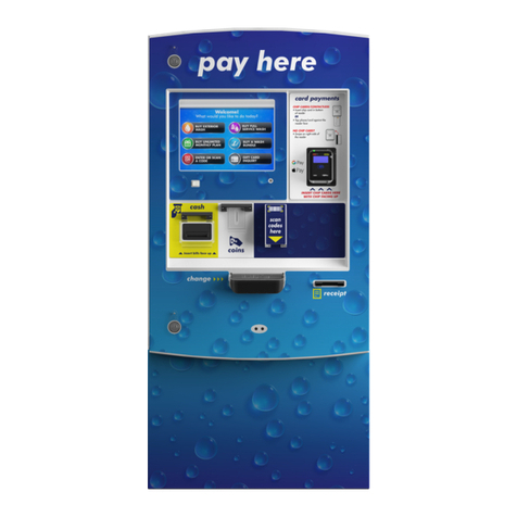
Hamilton
Hamilton HTK Pay Station installation manual

VeriFone
VeriFone M425 installation guide
Rapyd
Rapyd INGENICO MOVE 3500 MOBILE Getting started
Magtek
Magtek DynaPro Go Installation and operation manual

