HTK INSTALLATION MANUAL 4List of Figures
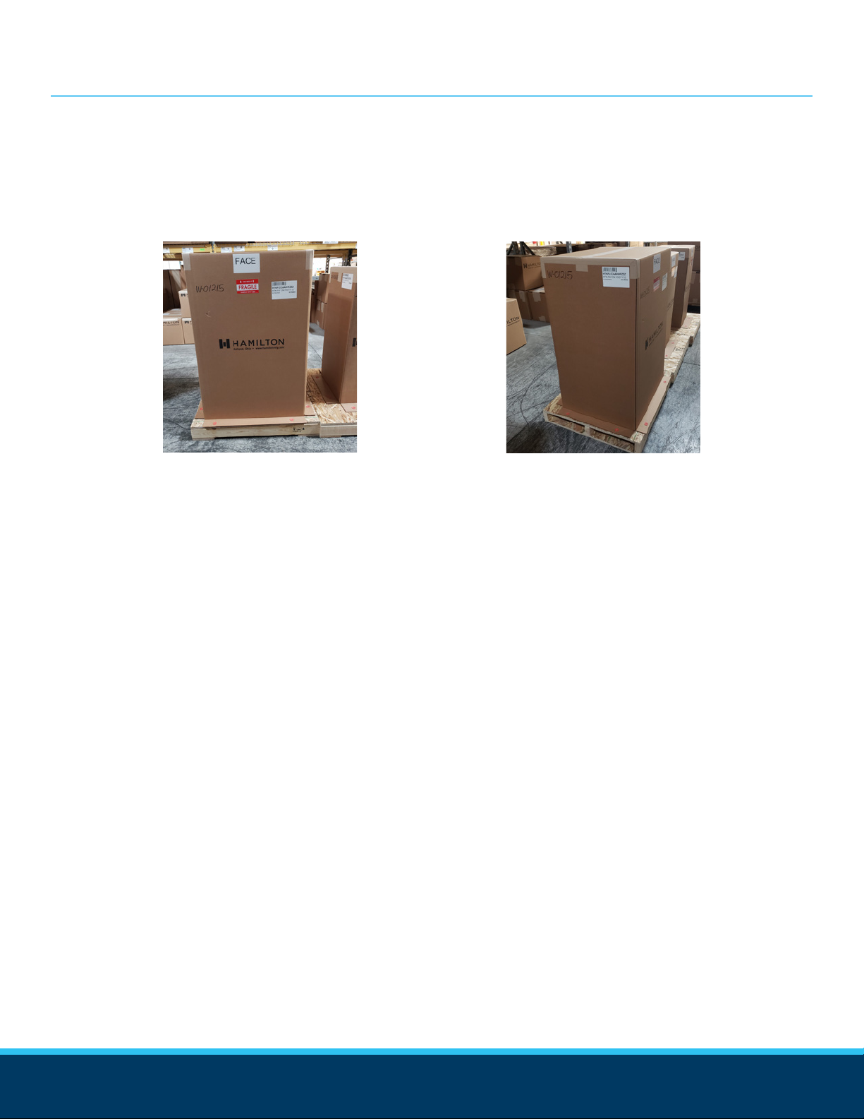
UNPACKING
Figure 1.1: HTK pallet (face) .................................................................
Figure 1.2: HTK pallet (side) .................................................................
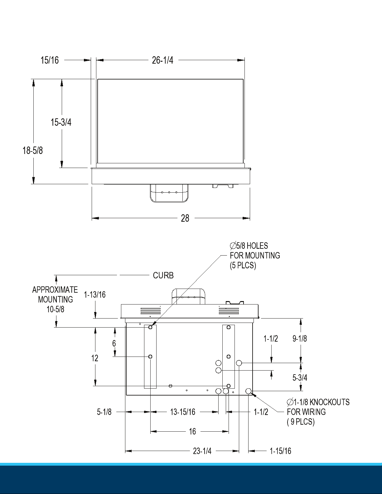
DIMENSIONS - BRICK-IN
Figure 2.1: Top of cabinet ....................................................................
Figure 2.2: Base of cabinet ..................................................................
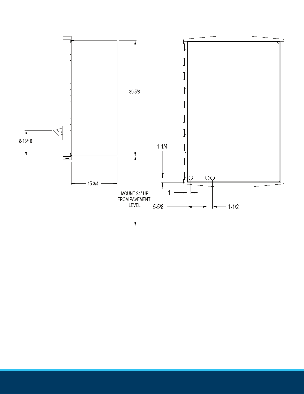
Figure 2.3: Side of cabinet ....................................................................
Figure 2.4: Rear of cabinet ...................................................................
Figure 2.5: Door ..................................................................................
BRICK-IN BOLT PATTERN
Figure 3.1: Brick-in HTK bolt pattern ...................................................
DIMENSIONS - FREE-STANDING
Figure 4.1: Top of cabinet .....................................................................
Figure 4.2: Base of cabinet ...................................................................
Figure 4.3: Sides of cabinet ..................................................................
Figure 4.4: Rear of cabinet ...................................................................
Figure 4.5: Door & base of HTK ............................................................
FREE-STANDING BOLT PATTERN
Figure 5.1: Free-standing HTK bolt pattern ............................................
LANE LAYOUT
Figure 6.1: Front view of brick-in lane layout ..........................................
Figure 6.2: Front view of free-standing lane layout .................................
Figure 6.3: Overhead view of lane layout ...............................................
Figure 6.4: Service door orientation .......................................................
ELECTRICAL DIAGRAMS
Figure 7.1: Power supply wiring connection ..........................................
Figure 7.2: Wash Interface diagram ......................................................
Figure 7.3: Wash Interface diagram, angled ..........................................
Figure 7.4: Gated Sequence Software Ether Vend (MIB Gate) ................
Figure 7.5: Gated Sequence Software Ether Vend (Micro Drive Gate) ......
Figure 7.6: Passive Cycles ....................................................................
Figure 7.7: Active Cycles ......................................................................
COMPONENT CONNECTIONS
Figure 8.1: Power supply connections ...................................................
Figure 8.2: Gen 5 controller connections ...............................................
Figure 8.3: Gen 4 controller connections ...............................................
Figure 8.4: Gen 3 controller connections ...............................................
Figure 8.5: Distribution board connections .............................................
Figure 8.6: Smart Bus Hub connections .................................................
Figure 8.7: Bill dispenser connections ....................................................
Figure 8.8: Stacker interface connections ...............................................
List of Figures
6
6
8
8
9
9
10
11
12
12
13
13
13
14
15
15
16
16
20
21
21
22
23
22
22
25
26
27
28
29
30
31
32