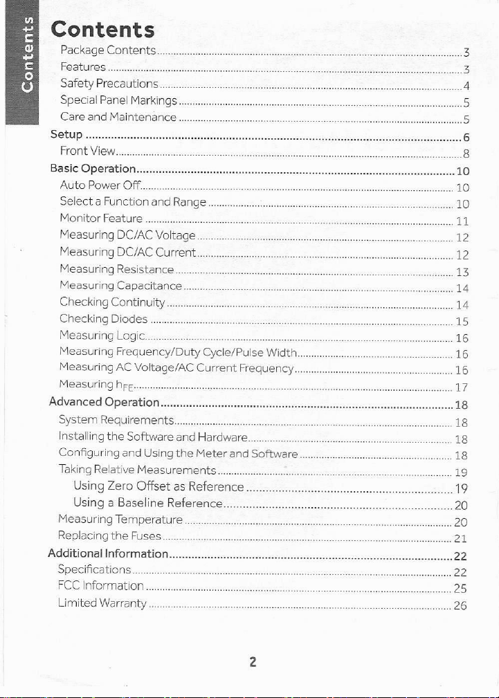
Radio Shack 2200087 User manual

(®
XN
radioshack
2200087
User's Guide
True RMS
Digital Multimeter
FCC Note:
The supplied USB
cable with ferrite
must be used with
your multimeter to
ensure compliance
with the Class BFCC
limits (Section 15.27). Ce
We hope you enjoy your True RMS Digital Multimeter from RadioShack. Please read this
user's guide before using your new multimeter:

Contents
Contents
Package Contents
Features ..
Safety Precautions
Special Panel Markings
Care and Maintenance
SEUUID emu nswos ners tssasonsebasebsenssstesiass savas aSEERea
Front View...
Basic Operation
Auto Power Off..................
Select aFunction and Range .
Mentor Feature: ..amsmmssssassass
Measuring DC/AC Voltage.
Measuring DC/AC Current.
Measuring Resistance.
Measuring Capacitanc
Checking Continuity................
Checking Diodes
Measuring Logic. :
Measuring Frequency/Duty Cycle/Pulse Width
Measuring AC Voltage/AC Current Frequency
Measuring heg.....
Advanced Operation
System Requirement:
Installing the Software and Hardware................
Configuring and Using the Meter and Softwar:
Taking Relative Measurements ....................
Using Zero Offset as Reference
Using aBaseline Reference......
Measuring Temperature ..
Replacing the Fuses........
oO
wo
tub
W
Additional Information
Specifications.
FCC Information =
Limited Warranty .............ococccerevcmeeeressssssssssssssssesssosseessess sesso 20

Package Contents
«Digital Multimeter «Test Leads (2)
PETER
Te)
+Rubber Boot -USB Cable
«K-type Thermocouple
a
«User's Guide —»Fuse 250V/12A (2 inside meter)
«Fuse 250V/500maA (2 inside meter)
Features
«Measures voltage, current, resistance, capacitance. frequency, temperature,
and more
+True RMS for more accurate AC voltage and current readings
« Auto-ranging with manual-ranging override
-Computer interface enables you to log and graph measurements
+6000-count digital LCD indication
«Auto power-off after 30 minutes to conserve battery life

Contents
Safety Precautions
Read and follow thesesafety precautions.
Never apply voltages to the meter that exceed the limits givenin the
specifications. Never apply more than 1000V DC or 750V RMS AC between
the input jacks and ground.
+Use extreme caution when working with voltages above 100V. Always
disconnect power from the circuit you are measuring before you connect test
leads to high-voltage points.
+Never connect the test leads to avoltage source when you set the meter's
function dial to H2/LOGIC, »)/D+, QAF mA/A/== or yA/A/=2.
+Always discharge any capacitors of the circuit under test before you attach
test leads.
+Always turn off power and disconnect the test leads from the circuit you are
testing before you replace the meter's battery or fuse. Never operate the meter
unless its back cover and battery cover are in place and secured.
+Never try to probe with both test leads at the same time or hold both test
leads in one hand.
+The testleads supplied with your meter are rated for 1000V. Use only test
leads ofthe same rating with the meter. You can order replacement leads
from your local RadioShack store.
+Donotuseafuse of brand or rating other than those specified here. Doing so
might damage your meter.
+Because many AC/DC sets have apotentially hot chassis, be sure the top
of your workbench and the floor underneath it are made of non-conductive
materials.
+Your multimeter is designed primarily to measure household AC voltages.
Because of the dangers inherent in measuring three-phase circuits, we
strongly recommend you do not use this meter to measure 3-phase, line-to-
line voltage. If you still want to, put on protective clothing—a face shield and
fireproof gloves and upper body protection is required before measuring. If
you do not have this protection, DO NOT MEASURE THESE CIRCUITS.
«Toreduce the risk of fire or shock hazard, do not expose this product to rain
or moisture. For indoor use only.
+When you are not using the meter, always turn it off.
+Ifthis equipment is used in amanner not specified in this user's guide, the
protection provided by the equipment may be impaired.
This meter is fully calibrated and tested. Under normal use, no further adjustment
should be necessary. If the meter requires repair, do nottry to adjust it yourself.
Take it to your local RadioShack store.

Special Panel Markings
ACAUTION: Risk of electric shock! Refer to the complete
operating instructions.
CAUTION: Be extremely careful when making high-
Avoltage measurements; DO NOT TOUCH TERMINALS OR
PROBE ENDS.
=] The meter is protected by double insulation.
Mee Th [tage that this met ei
750V— emaximum voltage that this meter can measure is
1000V DC or 750V AC. The maximum current thatthis
400mA terminal can measure is 400mA DC and AC.
MAX
+10A MAX The maximum current you can measure at this jack is 10A
FUSED DC/AC. This jack is fuse-protected.
CAT.I This equipment is rated for INSTALLATION CATEGORY II
:(3600VA max)
500V To avoid electrical shock or instrument damage, do not
MAX connect the common input terminal (=COM jack) to any
=k source that exceeds 500 volts with respect to earth/
-ground.
WARNING:
Shock Hazard
|
The sliding guard on the front of the meter protects
if guard not against electrical shock. Do not remove the guard.
installed.
Care and Maintenance
Keep the meter dry; if it gets wet, wipe it dry immediately and make sure that the
meter is completely dry before using it. Use and store the meter only in normal
temperature environments. Handle the meter carefully; do not drop it.
To keep the meter looking new, occasionally wipe it with acloth slightly dampened
with water. Do not use harsh chemicals, cleaning solvents, or strong detergents
to clean the meter.
S3Ud3U0)

Setup
@Install Batteries
1. Remove the rubber boot ifit is attached
2. Turn off your meter. Loosen the screw and remove
the battery cover.
3. Insert two AA batteries (not supplied), matching
the polarity symbols (+ and =) marked inside.
4. Secure the battery cover with the screw.
Battery Notes:
+Useonly fresh batteries of the required size and
recommended type.
+Dispose of old batteries promptly and properly. Do not burn or bury them.
+Ifyou do not plan to use the meter for amonth or more, remove the batteries.
Batteries can leak chemicals that can destroy electronic parts.
«= When[Z3 appears or the meter stops operating properly. replace the batteries.
(@ Use the Stand (Optional)
You can fold out the stand on the back of the meter to
place it upright on aflat surface for easier viewing.
®Use the Rubber Boot
(Optional)
The rubber boot protects your meter from damage and stores the test leads. You
can also use it to mount your meter on awall with ascrew
(not supplied).
Flip up to mount on ascrew.
Store the test leads
when notin use.

@Connect the Test
Leads
1. Remove the plastic plugs before
using your test leads.
2. Slide up the Sliding Guard to
show the test lead sockets.
3. Plug the black test lead into
~COM (common), then plug
the red test lead into +V.mA.Q.
To measure current higher than
400maA, plug the red test lead into
+10A MAX instead of +V.mA.Q.
AN WARNING:
=Although the test leads are rated for
1000 volts, and the maximum rating of
this meteris 1000 volts DC /750 volts
RMS AC, do not try to measure voltage
greater than 1000 volts DC /750 volts
RMS AC.
+The meter sounds awarning tone when you
set it to measure anything except current and
you connect atest lead to +10A MAX. This
reminds you not to touch the circuit with the
test leads.

Setup
Front View
Indicates auto range mode. The meter
automatically enters the auto range mode
when you turnit on.
£=%V/dBm
Measures DC and AC voltage in dBm or volts.
°C/°F
Measures temperature in Celsius or Fahrenheit.
HA/A/=
Measures current.
mA/A/=
Measures current.
Qrit
Measures ohms and capacitance.
o)/ Pk
Checks continuity and diodes.
Hz/LOGIC
Measures logic (HI/LO) /frequency.
hee
Measures the gain of small-signal bipolar
transistors.
OFF
Switches off the meter.
-COM
Plug the black lead into this jack.
+V.mA.Q-
Plug the red lead into this jack.
+10A MAX
Plug the red lead into this jack when measuring
current over 400mA.
il ——
gr gE:
Rubber Boot
+Protect the meter.
-Store the test leads.
+Mount the meter to awall.

HOLD
«Tests the display.
«Disables auto power-off.
«Pauses/continues measurement monitoring
{(maximum/minimum values).
Be SELECT
Toggles between measurement options within a
function.
RANGE
«Selects auto or manual ranging.
«Selects different ranges in manual range mode.
RELA
Takes relative measurements.
Hz/DUTY/WIDTH
Measures frequency, duty cycle, and pulse width.
MAX/MIN
Stores maximum and minimum readings.
Function/Power dial
Turns the meter on/off and selects the measurements.
Sliding Guard
DN Warning: The guard protects against
electric shock. Do not remove it.
Test Leads

~
2
Ed
©
A
(7)
a
o
=
wn
[3:3
[5
Basic Operation
Auto Power Off
When left unattended, your meter automatically turns off after 30 minutes. Press
any button to turn the meter back on
To disable the auto power off function:
1. Turn off your meter.
2. Pressand hold the HOLD and SELECT buttons simultaneously, then turn on
the meter. PLoc appears until you release both buttons.
To reactivate the auto power off function, turn the meter off, then back on.
Select aFunction and Range
Each position on the function dial accesses one or more individual functions.
To select afunction:
1. Turn the function dial to the position with the desired function
2. Press SELECT to toggle between the functions in each position. The unit of
measure that appears on the display shows the currently set range.
3. Press RANGE repeatedly to select arange.
Note the position of the decimal:
IF8.000V appears. the meter is set to measure less than 4volts. IF3380V
appears, the meter is set to measure up to 1000 volts.
10

Read the range in volts, ohms, capacitance, or amps as indicated by the position
of the decimal point.
600 mV ddd.d mv
6V d.dddv
60V dd.ddv
600V ddd.dVv
1000VvDC
/750V AC
|
9dddV
600 pA ddd.d pA
6000 pA
60 mA
400 mA
6A
10A
600 Q)
6kQ
60kQ
Monitor Feature
The meter's monitor feature stores the minimum or maximum measured value. If
the meter measures avalue outside that range, it updates the stored values.
The meter automatically sets itself to manual mode and disables auto power off
when you use itto monitor.
pe
OR
dddd pA
dd.dd mA
ddd.d mA
dddd A
dddd A
ddd.dQ
d.ddd kQ
dd.dd kQ
Set the meter to any function except °C/°F, dBm, *), TF, LOGIC, or hgg.
Connect the test leads to the circuit.
Press RANGE to select asuitable range.
Press MAX/MIN. MAX appears. Press MAX/MIN to toggle between the
ddd.d kQ
d.ddd MQ
dd.dd MQ
d.ddd nF
dd.dd nF
ddd.d nF
d.ddd pF
dd.dd pF
Lo]
I
1k
2]
Oo
od
{0}
=
I
=
<}
3
maximum value (when MAX appears) and minimum value (when MIN
appears).
5. To pause monitoring, press HOLD. HOLD appears. To continue monitoring,
press HOLD again.
6. To exit monitor mode, press and hold MAX/MIN until MAX or MIN
disappears.
t|Note: Ifthe meter is set to voltage or current function and the input is out of the
settings range, OF appears.
11

c
=
Ed
ro
Et
Q
=
(eo)
i
wn
es
0
Measuring DC/AC Voltage
You can measure AC voltage superimposed on aDC voltage source bias while
ignoring the DC voltage, but never try to measure an AC voltage that is riding on a
DC source bias where the peak AC voltage exceeds 1000V with respect to earth
ground.
NN WARNING: Do NOT try to measure aDC voltage above 1000 volts oran AC
voltage above 750 volts RMS, and never clamp atest lead to ahot wire (usually red,
black, or blue in AC wiring circuits). Ifone lead is clamped to ahot wire and you touch
the meters other probe, you could receive an electric shock.
1. Setthe function dial to =2V/dBm. To measure AC voltage, press SELECT to
show dBm or avolts unit with ~ in front of the value. To measure DC voltage,
press SELECT to show avolts unit without ~in front of the value.
2. Ifthe meter is set to automatic range control, it automatically moves to the
range that gives the best reading.
To manually set the range, press RANGE ([NUI[§] disappears). Press RANGE
again to change the range (if necessary)
3. Power off the circuit under test. Touch the test leads to the circuit.
Or, to measure AC voltage superimposed on aDC voltage source bias,
connect a0.1 microfarad (uF)/100V mylar capacitor (not included) in series
with the positive terminal of the circuit and the red test lead, then power on
the circuit and read the AC voltage.
©Note:
When the meter is set to the 600mV range, OF continues to appear even after
you remove an over-range input signal. This is normal. Touch the test leads
together or connect them to acircuit to make OF disappear.
+0dBmis equal to the consumption power on a 600-ohm resistor with 0.775V
voltage drop.
Measuring DC/AC Current
To measure DC/AC current. you must break the circuit and connect thetest leads
to two circuit connection points. The connection must be in series with the circuit
under test.
OD warning:
=Never connect the test leads across avoltage source. Doing so can damage
the meter or the circuit under test. The maximum input limit for AC/DC current
measurement is 10A.
12

9.
Ifyou do not know the amount of current in the circuit you are measuring, always
connect the red test lead to +10A MAX.
Rotate the function dial to pA/A/== for 600/6000pA and 6/10A ranges or to
mA/A/== for 60/400mA and 6/10A ranges.
Press SELECT to measure AC current (~ appears) or DC current
(~ disappears).
Power off the circuit under test and discharge all capacitors.
Plug the black test lead into ~COM and the red test lead into the appropriate
Jack.
Connect the meter's test leads in series with the circuit.
Apply power and read the current value. If the measurement is less than
400mA and the red test lead is connected to +10A MAX, power off the
circuit.
If your measurement exceeds the selected range, OF appears until the
measured current is reduced to the selected range.
Move the red test lead to +V.mA.Q.
Rotate the function dial to pA/A/== or mA/A/==, depending on the value
you measured in Step 6.
Reapply power to the circuit.
t1Note: Ifyou are measuring DC current and the current’s polarity is negative, =
appears before the value.
Measuring Resistance
1.
2.
3.
Power off the circuit under test and discharge all capacitors.
Rotate the function dial to Qk
If the display shows 8.8000 nF or 8.000 pF, press SELECT to change to the
Resistance function.
When you rotate the function dial to Q/1k, the meter resets to automatic
range control and automatically moves to the range that gives the best
reading.
To manually set the range, press RANGE ([X8I[#] disappears). Press RANGE
again to change the range (if necessary).
Touch the test leads across the resistor (that is, atest lead on each resistor
lead), or remove one of the component leads from its circuit and touch the
test leads across the resistor.
13
w
I
Ll
(2]
[o]
Bel
(}
=
i
=
0
=

c
=
Ed
©
i
7}
a
o
=
7)
1G
3
Goll Note:
+With no resistance connected across the test leads (meaning resistance is
infinite), OF appears when you measure resistance. This is normal.
+Ifyouare measuring resistance of about 1MC) or more, the display might take a
few seconds to stabilize. This is normal
+Tocalculate and measure avery small resistance, see “Taking Relative
Measurements” on page 19.
Measuring Capacitance
The capacitance-measuring circuit in your meter charges aconnected capacitor
to aspecific voltage level, then discharges the capacitor to alower voltage. The
meter measures the amount of time it takes to discharge the capacitor.
1. Power offthe circuit under test and discharge all capacitors.
2. Rotate the function dial to QA tand press SELECT until nF or pf appears
Attach the red test lead to the positive side of the capacitor and the black
test lead to the negative side. Or, remove one of the leads of the capacitor
fromits circuit and connect the test leads to the capacitor's matching
(positive or negative) terminals. The measured value appears.
Note:
The voltages applied across electrolytic capacitors affect their measured value.
Ameasurement taken with alow voltage will be lower than one taken with a
voltage near the capacitor’s voltage rating. Because this meter cannot use
high voltage to set the electrolyte, it cannot measure the absolute value of
capacitance.
+Forlow-value capacitors, the measurement might be very close to the meters
actual input capacitance. Use the meters relative feature to measure low
capacitance values. See “Taking Relative Measurements” on page 19.
+Capacitance measurement accuracy depends on the measurement method
and differs with different types of capacitors. The meter's measurement is for
reference only.
Checking Continuity
You can use the meter to check for shorted or open electrical circuits.
1. Power off the circuit under test and discharge all capacitors.
2. Rotate the function dial to 9k.
3. Press SELECT until") appears.
14

4. Touch the test leads across the circuit you want to measure.
Shrt appears and the buzzer sounds ifthe circuit resistance is less than
about 50 ohms (meaning the circuit is continuous or shorted).
Open appears and the meter's buzzer does not sound if the circuit resistance
is greater than about 50 ohms (meaning the circuit is not continuous).
Checking Diodes
You can check diodes, transistors, and other semiconductors for opens, shorts,
and normal operation, and determine the forward voltage and polarity for diodes.
Power off the circuit under test and discharge all capacitors.
2. Rotate the function dial to »)/$k.
3. Press SELECT. $F appears.
4. Connect the test leads to the device you want to check, or remove one
of the component leads from its circuit and connect the test leads to the
component. Note the first reading.
5. Reverse the test leads and note the second reading.
+If one reading shows avalue and the other is overrange (OF appears).
the device is good.
«If OF appears during both readings, the device is open.
+If both values are very small or zero, the device is shorted.
To check polarity of an unmarked diode:
Connect the test leads to the two sides of the diode. Measure and note the
voltage. Then, reverse the test leads, measure and note the second reading. The
side of the diode where the meter shows ahigher voltage using the red test lead
is the anode (+) side. The side of the diode where the meter shows OF using the
red test lead is the cathode (-)side.
aNote:
When you testasilicon-type semiconductor, the values might vary depending
on the temperature.
w
118
=
[3
le)
©
o
=
)
=
=]
3
=The values that appear during adiode check show the actual forward voltage
(3.0V max). If the voltage exceeds 3.0V. OF appears. The meter cannot check
this diode.
15

=
=
Ed
©
i
7)
o
le}
I)
(7)
fo
:]
Measuring Logic
DN WARNING: Do not apply more than 5V DC between terminals. This could
damage the meter orthe circuit being tested.
1. Rotate the function dial to Hz/LOGIC.
2. Press SELECT once. LO appears.
3. Connect the test leads to the device you want to check.
+LO appears if the logic is low (the voltage is lower than 1.0V).
+Hi appears if the logic is high (the voltage is higher than 2.0V)
+The actual voltage appears ifthe logic is between 1and 2V.
Measuring Frequency/Duty Cycle/Pulse
Width
The meter can measure frequency from 10Hz to 4MHz and duty cycle and pulse
width with asignal frequency from 10Hz to 100kHz. The amplitude of the signal
should not be larger than 10V peak
1. Rotate the function dial to Hz/LOGIC.
2. Press SELECT until Hz, KHz, or MHz appears.
Otherwise, press Hz/DUTY/WIDTH to select duty cycle function
(% appears) or pulse width function (uS or mS appears).
3. Connect the black test lead to aground reference for the signal, and connect
the red test lead to the signal source.
“
1Note: For Pulse Width and Duty Cycle, apply +5/-0V square wave.
Measuring AC Voltage/AC Current Frequency
The meter can measure the frequency of an AC voltage, with or without aDC
source bias.
NN WARNING: To avoid electrical shock and damage to the meter, never try to
measure afrequency of more than 1kHz between AC 40 volts RMS and 750 volts
RMS.
1. [Ifyou are measuring AC voltage with aDC source bias, set the function dial
to==V/dBm.
To measure AC current frequency.rotate the function dial to pA/A/== for
600/6000pA and 6/10A ranges or mA/A/2% for 60/400mA and 6/10A
ranges.
16

To select the frequency function, press Hz/DUTY/WIDTH until Hz, kHz, or
MHz appears.
To select the duty cycle or pulse width function, press Hz/DUTY/WIDTH
until %appears (to select duty cycle) or until pS or mS appears (to select
pulse width).
If %, pS, or m5 appears and you want to select the frequency function again,
press Hz/DUTY/WIDTH until Hz, kHz, or MHz appears.
Connect the test leads to the device you want to check
=Note:
Measuring hg
You can use the meter to measure the DC gain of
small-signal, bipolar transistors in the FE range of
1000
ND CAUTION: To avoid damaging the meter, do not try
to check atransistor ifyou do not know its type and pinout.
1.
2.
Ifthe function dial is set to =2V/dBm and you want to set the meter for
maximum sensitivity when measuring a new signal, press SELECT to select the
AC Vfunction then press Hz/DUTY/WIDTH to selectthe frequency function.
To change back to AC Vmeasurement, press SELECT once then press
SELECT again to select the AC Vdisplay mode (dBm or volts). Press SELECT
twice to set the meter back to the AC Vmeasurement function.
Ifthe meter is set to measure current, it cannot measure the frequency of a
signal with DC bias.
w
1
a
0
Oo
©
1)
=
i)
=
o
=
Set the function dial to hgg.
Unplug both test leads from the meter, then slide
down the Sliding Guard to show the hgg socket
Insert the transistor you want
to check into the hgg socket,
matching the pinout of the
transistor with the labels on heg Socket
the socket. The transistor's
value appears.
17

Advanced Operation
You can use the supplied USB cable to connect your meter to acomputer,
allowing you to monitor, record, and log data over aperiod of time. You can
even use your meter to display oscilloscope information on your computer. For
example, you can record changes in temperature in arefrigerator or voltage
changes in acircuit over aperiod of time.
System Requirements
Windows® 8/7, Windows Vista® Windows XP, Windows ME/2000/98
CPU Dual core 2.2 GHz [CPU 2.0GHz
RAM 15GB RAM 512MB
Harddisk 20GB Harddisk 10GB
Screen Screen
resolution leas resolution 800x600
Installing the Software and Hardware
1. Turn on your computer and start the installed Windows operating system.
2. Use the supplied USB cable to connect the multimeter to your computer.
Note the sticker Connect to PC on the cable.
3. Insert the software CD into your CD-ROM drive. Browse to the
CD-ROM drive to install the driver at:
meter view setup\win7, XP, Vista (or win8, or win98, ME, or win2000)\
Driver\Setup
4. Browse to the CD-ROM drive to install the multimeter application (Meter
View) at:
meter view setup\win7, XP, Vista (or win8, or win98, ME, or win2000)\
Application\MeterView Setup
c
9s
-
f=
He
el)
efiel
<0 5. Restart your computer.
Configuring and Using the Meter and
Software
After connecting, you must configure your meter and the Meter View software so
that they can work with each other.
1. Onyour computer, start the Meter View application.
18

Turn on your meter.
Press and hold SELECT and RANGE together. [SEN] appears.
Click the p- icon, or click Start in the Run drop-down menu, and then click the
Start button to set up the meter to work with your computer. Data is
transmitted from your meter to your computer. The display you see on the
meter also appears on your computer.
Note:
+Ifthe Meter View software stops communicating with the meter; check the
connection between the meter and the computer and make sure [ERI still
appears on the meters display.
«+ Meter Viewincludes installation files and ahelp file. Find the help file in the
Resources folder.
+Meter View allows five days ofdata logging, after which you will receive a
"Memory full" message. Click OK to save the data file.
Taking Relative Measurements
The meter allows you to take relative measurements for certain functions.
This allows you to measure very low resistance or identify closely matching
measurements.
This feature is not available for °C/°F, dBm, 9), ©, LOGIC, and hgg.
Using Zero Offset as Reference
The lowest scale on this meter is 400 ohms and the resolution is 1/10 of an ohm.
With lower resistances (for example, a1ohm resistor), the resistance in the
meter's test lead can produce areading error. The zero offset feature subtracts
any resistance from the meter leads.
1. Select the function (not °C/°F, dBm, 9), DF LOGIC, or hg).
2. Select the 600Q range.
3. Measure the zero offset. For capacitance, disconnect test leads. For other
functions, touch the test leads together.
O
5-1
0
3
3)
et
0)
=
padueApy
4. Intheory, the meter will read 0.0. If you see anon-zero reading, press
RELA Rel Aappears. The reading will be subtracted from subsequent
measurements.
5. Take ameasurement. You will get the actual value for the measured
component.
19

Using aBaseline Reference
Abaseline reference allows you to compare componentsdirectly. For example,
you can compare resistors in aset by measuring one resistor as the baseline and
then measuring how closely the remaining resistors match the baseline.
1. Select the function (not °C/°F, dBm, 9), DF, LOGIC, or hg).
2. Press RANGE to select arange
3. Connect the test leads to the component whose measurement you want to
use as abaseline.
4. When you see the reading, press RELA. Rel Aappears and the meter sets
to manual range
5. Take ameasurement for another component. Rather than the actual
measurement value, the meter will display the component's variation from
the baseline (0.20. 0.01,-0.13,-0.02, etc.). If the measured value is lower
than the baseline, the meter will show anegative relative value. Areading of
0.00 indicates an exact match.
»To stop relative measurement, press RELA again or set the function dial to
another setting.
Note:
+Forthe most accurate reading, the temperature should be between 65°F and
83°F (18°C and 28°C), with amaximum of 75% relative humidity.
Relative and baseline measurements MUST always be in the manual ranging
mode.
+When measuring voltages in zero offset or baseline mode, the noise ofthe
environment you are measuring in could interfere with measurements.
Measuring Temperature
{N warning:
+Donotuse the thermocouple to measure objects when the voltage is above
30VRMS and 42.4Vpeak or 60V DC,
=Measuring high temperatures with the included probe can cause personal injury
(including burns) or damage to the thermocouple’s probe.
Set the function dial to °C/°F.
2. Plug the thermocouples black lead into ~COM (common), then plug itsred
lead into +V.mA.Q.
3. Press SELECT to select Celsius (°C) or Fahrenheit (°F).
Goji
x
ed
=
ae
ET
Beoo8
<O
20
Table of contents
Other Radio Shack Multimeter manuals

Radio Shack
Radio Shack 22-218 User manual

Radio Shack
Radio Shack 22-812A User manual

Radio Shack
Radio Shack 22-812 User manual

Radio Shack
Radio Shack 22-602 User manual

Radio Shack
Radio Shack 2200813 User manual

Radio Shack
Radio Shack 22-174A User manual

Radio Shack
Radio Shack 22-178 User manual

Radio Shack
Radio Shack 22-813 User manual

Radio Shack
Radio Shack 22-168A User manual

Radio Shack
Radio Shack 22-812 User manual