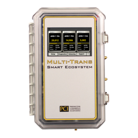
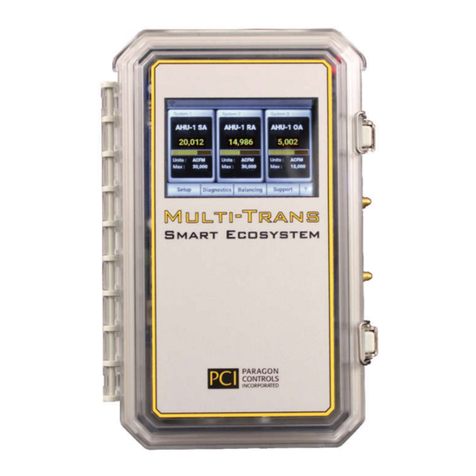
PCI OAFE-1550 Manual

OAFE-1550
Outdoor Airflow Measurement System
Operation & Maintenance Manual
Engineered for accuracy, applicability,
durability and simplicity in HVAC air systems


OAFE-1550 Operation & Maintenance Manual
Paragon Controls Incorporated i Revision Level 000
TABLE OF CONTENTS
TABLE OF CONTENTS............................................................................................................................. i
1. INTRODUCTION .............................................................................................................................. 1
1.1. DESCRIPTION........................................................................................................................... 1
1.2. BASIC OPERATION ................................................................................................................. 1
1.3. SAFETY ..................................................................................................................................... 2
1.3.1. Electrical Connections ........................................................................................................ 2
1.3.2. Static Electricity.................................................................................................................. 2
2. AIRFLOW MEASUREMENT STATION......................................................................................... 3
2.1. TYPICAL INSTALLATIONS ................................................................................................... 3
2.2. INSTALLATION GUIDELINES FOR DUCTED APPLICATIONS ....................................... 4
2.3. MAINTENANCE ....................................................................................................................... 4
2.4. SITE STORAGE, HANDLING, AND SPARE PARTS ............................................................ 4
3. SIGNAL PROCESSOR INSTALLATION........................................................................................ 5
3.1. NEMA 1 MECHANICAL INSTALLATION ............................................................................ 5
3.2. NEMA 4 MECHANICAL INSTALLATION ............................................................................ 6
3.3. ELECTRICAL & PNEUMATIC INSTALLATION.................................................................. 7
3.4. INPUT/OUTPUT SET-UP ......................................................................................................... 8
3.4.1. Process output ..................................................................................................................... 8
3.4.2. Temperature Input (Option)................................................................................................ 8
3.5. COMMON CONFIGURATION CHANGES ............................................................................ 8
3.5.1. Area Factor.......................................................................................................................... 8
3.5.2. Operating Range ................................................................................................................. 9
4. SIGNAL PROCESSOR POWER-UP CONFIGURATION............................................................. 10
4.1. ACTIVE POWER-UP DISPLAY............................................................................................. 10
4.1.1. Active Display Descriptions ............................................................................................. 10
4.2. KEY FUNCTIONS................................................................................................................... 11
5. SIGNAL PROCESSOR DISPLAY MENUS ................................................................................... 12
5.1. FIELD & TECH CONFIG MENUS......................................................................................... 12
6. SIGNAL PROCESSOR FIELD MENUS......................................................................................... 13
6.1. OPERATING RANGE ............................................................................................................. 13
6.2. ZERO PRESSURE CALIBRATION ....................................................................................... 13
6.3. ENGINEERING UNITS........................................................................................................... 13
6.4. LOCKDOWN ........................................................................................................................... 14
6.5. LOCKDOWN DELAY............................................................................................................. 14
6.6. FLOW CORRECTION............................................................................................................. 15
6.7. AUTOZERO (OPTIONAL) - STATUS................................................................................... 15
6.8. AUTOZERO (OPTIONAL) - INTERVAL .............................................................................. 16
6.9. AUTOZERO (OPTIONAL) - TEST INTERVAL ................................................................... 16
6.10. TEMP. COMP. (OPTIONAL) - TEMP. UNITS ...................................................................... 16
6.11. TEMP. COMP. (OPTIONAL) - TEMP. VALUES .................................................................. 17
6.12. TEMP. COMP. (OPTIONAL) - TEMP. INPUT ...................................................................... 17
6.13. TEMP. COMP. (OPTIONAL) - FIXED VALUE .................................................................... 17
6.14. DISPLAY FILTER ................................................................................................................... 18
6.15. OUTPUT FILTER - PROCESS................................................................................................ 18
6.16. ALARM OPTIONS (OPTIONAL) - ALARM STATUS......................................................... 18
6.17. ALARM OPTIONS (OPTIONAL) - ALARM VALUES ........................................................ 19
6.18. ALARM OPTIONS (OPTIONAL) - ALARM DELAY .......................................................... 19

OAFE-1550 Operation & Maintenance Manual
Paragon Controls Incorporated ii Revision Level 000
TABLE OF CONTENTS
6.19. DP DISPLAY FORMAT - DISPLAYED ONLY IN PRESSURE MONITOR MODE.......... 19
6.20. FACTORY DEFAULTS .......................................................................................................... 20
7. SIGNAL PROCESSOR TECH CONFIG. MENUS......................................................................... 21
7.1. AREA FACTOR....................................................................................................................... 21
7.2. MIN. CALIBRATION.............................................................................................................. 21
7.3. 50% CALIBRATION - DISPLAYED ONLY IN PRESSURE MONITOR MODE ............... 21
7.4. SPAN CALIBRATION ............................................................................................................ 22
7.5. TEMP. COMP. (NO TEMP. COMP OPTIONAL) - FIXED VALUE .................................... 22
7.6. ALTITUDE............................................................................................................................... 22
7.7. PROCESS OUTPUT CAL ....................................................................................................... 23
7.8. CORRECTION COEFFICIENT – PROBE CALCULATION COEFFICIENT...................... 23
7.9. CORRECTION COEFFICIENT - PIEZOMETER RING CALCULATION COEFFICIENT 23
7.10. 4PT FLOW CORRECTION ..................................................................................................... 24
7.11. PRE-FILTER ............................................................................................................................ 24
7.12. MAC ADDRESS (BACNET COMMUNICATION OPTION) ............................................... 25
7.13. INSTANCE CODE (BACNET COMMUNICATION OPTION)............................................ 25
7.14. MODBUS ID (MODBUS COMMUNICATION OPTION).................................................... 25
7.15. BAUD RATE............................................................................................................................ 26
8. SIGNAL PROCESSOR WARNING MESSAGES.......................................................................... 27
8.1. INPUT PRESSURE OVERRANGE MESSAGE..................................................................... 27
8.2. TRANSDUCER CALIBRATION MESSAGE ........................................................................ 27
8.3. AREA FACTOR MESSAGE ................................................................................................... 27
9. SIGNAL PROCESSOR TROUBLESHOOTING GUIDE............................................................... 28

OAFE-1550 Operation & Maintenance Manual
Paragon Controls Incorporated 1 Revision Level 000
1. INTRODUCTION
1.1. DESCRIPTION
The OAFE-1550 is an AMCA certified outdoor airflow measurement system with integral signal
processor that is capable of producing an overall ±0.5% accuracy through the velocity range of 200 to
1,200 fpm and ±5% accuracy at 100 fpm.
The airflow measurement station consists of multiple airflow elements, factory mounted and pre-piped
in a casing designed for flanged connection to ductwork, control dampers, louvers, etc. An optional
inlet bell is available for plenum applications. Standard materials consist of a G90 galvanized casing
and 6063-T5 anodized aluminum flow sensors, suitable for most HVAC applications. The airflow
averaging elements are head type devices, which generate a differential (velocity) pressure signal similar
to the orifice, venture, and other head producing primary elements. The airflow measurement station is
constructed so as to comply with ASHRAE Standard 111 for equal area traversing of an airflow
measurement plane. Multiple elements are manifolded together for connection to the integral airflow
signal processor.
The signal processor utilizes current state-of-the-art digital microprocessor technology capable of
producing unequaled 24-bit (16,777,216 steps) A/D and 12 bit (4,096 steps) D/A signal conversion
resolution. Having a twelve-point linearization capability, the signal processor can be field calibrated to
accurately determine true airflow rates even when the primary airflow measurement stations do not meet
their minimum installation requirements. The ultra low operating ranges and the auto zeroing function
of the signal processor provides accurate airflow measurement down to 100 fpm. The signal processor
accepts a temperature input signal for air temperature indication, temperature signal transmission for
remote readout, and air density compensation for standard or actual airflow calculations. A password
protected configuration menu provides quick and simple field configuration by authorized personnel.
Field configuration of engineering units, process noise filtering, operating range, alarm set points, etc,
are performed via user friendly menus and a six button touch pad.
An optional temperature transmitter with 4 to 20mA output and temperature range of -30 to 130°F is
available to provide a temperature input signal to the signal processor for air density compensation (see
the associated installation, operation and maintenance manual for further information).
1.2. BASIC OPERATION
The airflow measuring station produces pneumatic output signals referred to as total (high) and static
(low) pressure. These two pressures are piped to the signal processor where the static pressure is
subtracted from the total and the result indicated as velocity pressure. This measured differential
pressure is equal to the average velocity of the air stream moving through the plane that the airflow
measuring station is located in. This signal can be converted to air velocity and flow using the following
equations:
a
a
T
460
921.29
325.1
a
V
P
V
7.1096
AVQ
Where:
a
Actual density of air, in lb/ft
3
(0.075 lb/ft
3
at sea level and 68°F)
a
T= Actual temperature, in °F (default value is 68°F)
P
V
= Velocity pressure, in inches H
2
O
V = Velocity, in fpm
Q = Flow, in cfm
A = Area, in ft2
This signal is scaled and linearized before being displayed and transmitted out as a 4-20ma, 0-5vdc, or
0-10vdc signal.

OAFE-1550 Operation & Maintenance Manual
Paragon Controls Incorporated 2 Revision Level 000
The AutoZero option detects and corrects any zero offset caused by large ambient temperature changes.
The Temperature Compensation option compensates the flow and velocity signal for density changes
caused by variations in the process air temperature. An external temperature transmitter is required.
1.3. SAFETY
1.3.1. Electrical Connections
Before any electrical connections are made, ensure the POWER SWITCH is in the OFF position.
1.3.2. Static Electricity
The circuit board contains components which are susceptible to damage caused by static electrical
discharge. Should it be necessary to remove the circuit board from the enclosure, appropriate
precautions must first be taken to ensure that the operator and the circuit board are at the same electrical
potential.

OAFE-1550 Operation & Maintenance Manual
Paragon Controls Incorporated 3 Revision Level 000
2. AIRFLOW MEASUREMENT STATION
2.1. TYPICAL INSTALLATIONS
ROOFTOP AHU WITH RAIN HOOD
EXTERIOR MOUNTED AIRFLOW STATION ROOFTOP AHU WITH RAIN HOOD
INTERIOR MOUNTED AIRFLOW STATION
OA INTAKE PLENUM
(BY OTHERS)
OA CONTROL
DAMPER
(BY OTHERS)
AIRFLOW
STATION
F
L
O
W
RAINHOOD
(BY OTHERS)
OA INTAKE PLENUM
(BY OTHERS)
OA CONTROL
DAMPER
(BY OTHERS)
AIRFLOW
STATION
F
L
O
W
RAIN HOOD
(BY OTHERS)
OUTDOOR AIR PLENUM MOUNTED AIRFLOW
STATION OUTDOOR AIR PLENUM MOUNTED AIRFLOW
STATION
LOUVER
(BY OTHERS)
OA INTAKE PLENUM
(BY OTHERS)
OA CONTROL
DAMPER
(BY OTHERS)
F
L
O
W
AIRFLOW
STATION
LOUVER
(BY OTHERS)
OA INTAKE PLENUM
(BY OTHERS)
OA CONTROL
DAMPER
(BY OTHERS)
AIRFLOW
STATION
F
L
O
W
PLENUM MOUNTED MINIMUM OUTDOOR
AIRFLOW STATION DUCTED OUTDOOR AIRFLOW STATION
OA INTAKE PLENUM
(BY OTHERS)
DAMPER
ECONOMIZER
(BY OTHERS)
OA CONTROL
DAMPER
(BY OTHERS)
LOUVER
(BY OTHERS)
F
L
O
W
AIRFLOW
STATION
OA INTAKE PLENUM
(BY OTHERS)
OA CONTROL
DAMPER
(BY OTHERS)
AIRFLOW
STATION
FLOW

OAFE-1550 Operation & Maintenance Manual
Paragon Controls Incorporated 4 Revision Level 000
2.2. INSTALLATION GUIDELINES FOR DUCTED APPLICATIONS
The station may be installed in any duct configuration. However, the accuracy of the installation is
dependent on the flow conditions in the duct. The minimum installation requirements based upon a
uniform velocity profile approaching the duct disturbance for flow rates less than 2,500 fpm are shown
below. These are not ideal locations. It is always best to locate the station as far as possible from all
duct disturbances, with upstream disturbances being the most critical consideration.
OPPOSED BLADE DAMPERS
2D
ELBOWS
3D
FLOW
D
FLOW
2D
FLOW
D/4
FLOW
D/6
FLOW FLOW
15° MAX
TRANSITIONS
D/6
2D
4D
FLOW
D/2
FLOW
DUCT TAKE-OFFS
FLOW
D
Notes:
Rectangular Ducts:
D =
HW4H = Duct height W = Duct width
2.3. MAINTENANCE
Since the sensing elements have no moving parts, only periodic cleaning may be required. The sensing
elements should be inspected for fouling of the sensing holes as part of an annual preventative
maintenance program. Installations having viscous airborne particles may require more frequent
inspection. If the sensing holes on the elements have become fouled or plugged, the following
procedure is recommended. Caution, all instruments must be isolated (removed) from the sensing
lines prior to performing the following cleaning procedure.
- Backpurging: Connect clean/dry compressed air, set at a maximum pressure of 25 psi, to the
output pressure ports (total and/or static) of the sensing element being cleaned. While
purging the sensing element, wipe the surface of the cylinder with a cloth or brush to loosen
and remove all contaminant buildup.
- Cleaning: In applications where the sensing elements are subject to viscous contaminants it
is recommended that the surface be washed with a cleaning agent. The cleaning agent used
must be suitable for use on the type of material the sensing element is constructed of (i.e.
aluminum, stainless steel, etc.)
2.4. SITE STORAGE, HANDLING, AND SPARE PARTS
The sensing elements must be stored indoors, in the original shipping package, and in a dry place.
Failure to do so may result in internal blockage of averaging chambers due to dust migration and/or
insect infestation. Although the sensing elements are not fragile by design, care must be taken not to
damage or disfigure the cylinder surface when handling and installing. Particular attention must be
given to the surface areas in which sensing ports are located. The sensing elements come as a complete
fabricated assembly. No spare parts are required.

OAFE-1550 Operation & Maintenance Manual
Paragon Controls Incorporated 5 Revision Level 000
3. SIGNAL PROCESSOR INSTALLATION
3.1. NEMA 1 MECHANICAL INSTALLATION
Refer to Figure 3.0 for installation clarification.
2.265"
7.625" PG21(3/4")
PG13.5(1/2") - TYP OF 3
CONTROLS
INCORPORATED
PARAGON
PCI
SIGNAL PROCESSOR
MicroTrans
4.625"
EQ
3.500"
8.250"
75 F
ACFM
*
1,225
FIGURE 3.0

OAFE-1550 Operation & Maintenance Manual
Paragon Controls Incorporated 6 Revision Level 000
3.2. NEMA 4 MECHANICAL INSTALLATION
Refer to Figure 3.1 for installation clarification.
PG13.5(1/2") PG13.5(1/2")
MOUNTING SCREW DIA. UP TO 1/4".
8.2"
(TYP OF 2)
STANDARD 1/4" COMPRESSION OPTION
5.0"
I.D./DATA LABEL
PARAGON
INCORPORATED
CONTROLS
PCI
MicroTrans
SIGNAL PROCESSOR
1,225
75 F
ACFM
EQ
*
PG13.5(1/2")
PG21(3/4")

OAFE-1550 Operation & Maintenance Manual
Paragon Controls Incorporated 7 Revision Level 000
3.3. ELECTRICAL & PNEUMATIC INSTALLATION
Refer to Figure 3.2 for electrical and pneumatic installation clarification.
- Nema 4 Option - Remove the MicroTrans
EQ
cover by turning each corner cover mounting
screw counter clockwise.
- Both Nema 1 & Nema 4 enclosures incorporate three 1/2" conduit connections and one 3/4"
conduit connection to interface all electrical wiring and pneumatic tubing to the device.
Determine which conduit connection will be used and remove the black plug and install the
appropriate conduit fitting (By Others).
- The three electrical connectors located on the MicroTrans
EQ
board have removable plugs for
ease of installing the interface wiring. (Caution - All electrical connections must be made
with the MicroTrans
EQ
power switch in the OFF position)
J1
1 2 3 111213141516171845678
J3 (ALARM OPTION)
J2
ON
OFF
POWER
SWITCH
ENTER
ESC
109
LON
INPUT
TEMP.mA
V
PROC.
OUTPUT
mA
V
10V
5V
(24VAC/DC)
POWER SUPPLY
TEMP.
TRANSMITTER
(4-20mA LOOP
POWERED)
+
-
(4-20mA OUTPUT)
TEMP.
TRANSMITTER (0-10VDC OUTPUT)
TEMP.
TRANSMITTER
RECEIVING DEVICE
(PROCESS)
S1 S2 S4
-
+
-
+
+
-
+ 24VDC LOOP POWER
- TEMPERATURE INPUT(GND)
+ TEMPERATURE INPUT
+ NETWORK COMMUNICATIONS
- NETWORK COMMUNICATIONS
- PROCESS OUTPUT(GND)
+ PROCESS OUTPUT
8
10
9
EARTH GROUND
1
24VAC / DC
3
2
J1
4
6
7
5
J2
J3 (ALARM OPTION)
15
17
18
16
11
13
14
12
NC
LOW ALARMNO
NC
COM
HIGH ALARM
COM
NO
TYPICAL FLOW ELEMENT CONNECTION
CONNECTION
TOTAL (HIGH)
PRESSURE CONNECTION
PRESSURE
STATIC (LOW)
Tp CONNECTION
FE-1000
Sp CONNECTION
PURGE HOLD
FIGURE 3.2

OAFE-1550 Operation & Maintenance Manual
Paragon Controls Incorporated 8 Revision Level 000
3.4. INPUT/OUTPUT SET-UP
The MicroTrans
EQ
has been configured and calibrated at the factory for your specific requirements.
Refer to MicroTrans
EQ
Set-Up label located on the left side of unit to verify correct Input/Output
configuration for the application. Refer to chart and Figure 3.2 above if input or output configuration
changes are required.
3.4.1. Process output
To change the output configuration, set the S2 & S4 switches as follows:
Process Output Range S2 S4
Current 4-20mA NA mA
Voltage 0-10vdc 10V V
Voltage 0-5vdc 5V V
3.4.2. Temperature Input (Option)
To change the input configuration, set the S1 switch as follows:
Temperature Input S1 Switch Selection
4-20mA mA
0-10VDC V
3.5. COMMON CONFIGURATION CHANGES
3.5.1. Area Factor
Allows user to enter or modify an existing Area Factor. The area factor can be entered or modified as
follows:
Step 1. From the active display, enter the Tech. Config. menu by pressing the Up/Down
buttons simultaneously.
Step 2. Enter password number 1000 and press Enter button.
Step 3. Press the Enter Button once to access the Area Factor menu.
Step 4. Enter new Area Factory using Up/Down/Left/Right buttons.
Step 5. Press Enter button once.
Step 6. Press ESC button once.
Step 7. The active display should now be displayed.
Tech. Config.
Password: 1000
Area Factor Area Factor
Zero Calibration (FT
2
)
50% Calibration (001.000)
Span Calibration (Press Enter)

OAFE-1550 Operation & Maintenance Manual
Paragon Controls Incorporated 9 Revision Level 000
Warning Message:
Op Range Outside
allowable Value
Op Range will be
reset to the MAX
F.S. value
If the new Area Factor causes the existing Operating Range value to be outside the new calculated Min.
or Max Full Scale value, the Operating Range will be reset to the new Max Full Scale value. The
display will automatically jump to the Op Range menu allowing the user to enter a new Operating
Range value. This can be accomplished by performing the steps under Section 2.5.2 Operating Range.
3.5.2. Operating Range
The Operating Range allows the user to enter a value which will represent 100% of the process output
signal. The menu will display the Maximum Full Scale value possible for the user to enter as the
Operating Range. The Operating Range can be changed by using the following steps:
Step 1. From the active display, enter the Field menu by pressing and holding the Enter button
for 3 seconds.
Step 2. Press the Enter button once to access the Operating Range menu.
Step 3. Enter new Operating Range using Up/Down/Left/Right buttons.
Step 4. Press the Enter button once.
Step 5. Press ESC button twice.
Step 6. The active display should now be displayed.
Step 7. Process Output is automatically rescaled to the new Operating Range.
Field Setup
Menu
Operating Range Operating Range
Zero Calibration (6,000-12,000)SCFM
Engineering Units Enter Value
Lockdown (10,000) SCFM

OAFE-1550 Operation & Maintenance Manual
Paragon Controls Incorporated 10 Revision Level 000
4. SIGNAL PROCESSOR POWER-UP CONFIGURATION
4.1. ACTIVE POWER-UP DISPLAY
Upon initial power-up, Software Revision information will be displayed on the graphic display for
approximately 5 seconds.
EQ-1
Software Rev. XX.XXX
BACnet Rev. XX.XXX
4.1.1. Active Display Descriptions
After power-up initialization, the following information will appear on the graphic display depending
upon the options purchased.
* 75˚F * 75˚F *
0
.0000
000,000
000,000
AutoZero Inch w.c. High Alarm ACFM Low Alarm ACFM
Pressure Monitoring with an
Auto Zero Cycle
Flow Monitoring with a
High Alarm Condition
Flow Monitoring with a
Low Alarm Condition
Number Description
1 Process units
2 Air Flow temperature units in F or C (Temperature Compensation Option)
3 Flashing Asterisk indicates the CPU is functioning
4 Engineering units
5 Displayed during an AutoZero cycle (AutoZero Option)
6 Indicating High Alarm value has been exceeded (Hi/Lo Alarm Option)
7 Indicating Low Alarm value has been exceeded (Hi/Lo Alarm Option)
123
4
5
6
7

OAFE-1550 Operation & Maintenance Manual
Paragon Controls Incorporated 11 Revision Level 000
4.2. KEY FUNCTIONS
The following figure and description identify the function of each button.
J1
1 2 3 111213141516171845678
J3 (ALARM OPTION)
J2
ON
OFF
POWER
SWITCH
ENTER
ESC
109
LON
INPUT
TEMP.mA
V
PROC.
OUTPUT
mA
V
10V
5V
S1 S2 S4
21
3
4
5
6
78
Number Description
1 Enter Key - Allows a user to enter into the Field Menu, enter into a selected menu item
or store into memory changes made to the program.
2 Up Key - Allows the user to scroll up in the menu list to a selected item or increase
digits when making value changes.
3 Right Key - When making changes to user values the right key allows the user to scroll
to the correct digit for changes.
4 Down Key - Allows the user to scroll down in the menu list to a selected item or
decrease digits when making value changes.
5 Left Key - When making changes to user values the left key allows the user to scroll to
the correct digit for changes.
6
Escape Key - The Escape key allows the user to back out of the menu to the active
display. If a user starts to make a change and decides to cancel the change, the Escape
key will allow the user to return to the Active Display without making the change (see
Section 3.1 Active Display).
7 Power Switch – Allows a user to turn power off to the MicroTrans
EQ
during field
wiring changes or modifications to the device.
8 Lon Switch – Allows a user to send a unique Neuron device ID when connecting to a
LonWorks communication network.

OAFE-1550 Operation & Maintenance Manual
Paragon Controls Incorporated 12 Revision Level 000
5. SIGNAL PROCESSOR DISPLAY MENUS
5.1. FIELD & TECH CONFIG MENUS
The following table shows the Field and Tech. Config menus for devices set to monitor Flow, Velocity
and Pressure. The display will vary depending upon the options purchased.
MicroTrans
EQ
Setup for Flow or Velocity
Field Setup Menu
(Press ENTER button)
Tech. Config. Menu
(Press UP/DOWN buttons simultaneously)
(Enter Password number 1000)
(Press ENTER button)
Operating Range Area Factor (FT
2
)
Zero Calibration Min Calibration
Engineering Units Span Calibration
Lockdown Altitude
Flow Correction Output Calibration
AutoZero Correction Coefficient
Temp. Comp. 4PT Flow Correction
Display Filter Pre-Filter
Output Filter MAC Code
Alarm Options Instance Number
Factory Defaults Modbus ID
Baud Rate
MicroTrans
EQ
Setup for Pressure
Field Setup Menu
(Press ENTER button)
Tech. Config. Menu
(Press UP/DOWN buttons simultaneously)
(Enter Password number 1000)
(Press ENTER button)
Operating Range Min Calibration
Zero Calibration 50% Calibration
Engineering Units Span Calibration
AutoZero Output Calibration
Display Filter MAC Code
Output Filter Instance Number
Alarm Options Modbus ID
DP Display Format Baud Rate
Factory Defaults

OAFE-1550 Operation & Maintenance Manual
Paragon Controls Incorporated 13 Revision Level 000
6. SIGNAL PROCESSOR FIELD MENUS
To enter the Field Setup Menu; depress and hold the Enter button for 5 seconds.
6.1. OPERATING RANGE
This menu allows the user to view the range of values possible for the user to enter as the Operating
Range. The Operating Range value entered will represent 100% process output signal (5vdc/10vdc or
20mA).
Field Setup
Menu
Operating Range Operating Range
Zero Calibration (ACFM)
Engineering Units (6,000-12,000)
Lockdown (10,000)
6.2. ZERO PRESSURE CALIBRATION
The Zero Calibration menu allows the user to perform a zero transducer calibration to eliminate any
transducer zero shift.
(Caution: Before performing a zero calibration, disconnect the Total (High) and Static (Low)
pressure connections, perform a zero calibration and then reconnect the Total and Static pressure
connections).
Field Setup
Menu
Operating Range Input Value CPU Taking
Zero Calibration (0.000) in. W.C. Samples
Engineering Units
Lockdown
(Press Enter) (Please Wait)
6.3. ENGINEERING UNITS
A list of engineering units are available for the user to select from for display purposes to meet customer
requirements. Changing the engineering units will affect the process display and the alarm value menus.
Field Setup
Menu
Operating Range Eng. Units
Zero Calibration
Engineering Units (ACFM)
Lockdown

OAFE-1550 Operation & Maintenance Manual
Paragon Controls Incorporated 14 Revision Level 000
Standard Flow
Units Actual Flow
Units
Standard
Velocity
Units
Actual Velocity
Units Pressure
Units
SCFM ACFM SFPM AFPM Inch w.c.
SCFH L/S Sm/s Am/s Pa
SL/S Am
3
/
S % % KPa
Sm
3
/S % mm w.c.
Sm
3
/HR %
%
6.4. LOCKDOWN
Due to the high square root gain associated with very low delta p values, the output is locked to zero
output value until the output value reaches the specified LockDown value entered. Above the
LockDown value the output is linear to air flow. The LockDown value can be changed from 0 to 20% of
Operating Range value. Lock-down values can be changed in 1% increments. The recommended
standard is 10%.
Field Setup
Menu
Operating Range Lockdown (0-20%)
Zero Calibration (10)%
Engineering Units Delay (0-10 sec)
Lockdown (2) Sec
6.5. LOCKDOWN DELAY
The Lockdown Delay menu allows the user to enter a lockdown time delay (0-10 seconds) that will
delay the display and output lockdown from occurring until the flow value or output value has remained
below the lockdown value for that duration.
Field Setup
Menu
Operating Range Lockdown (0-20%)
Zero Calibration (10)%
Engineering Units Delay (0-10 sec)
Lockdown (2) Sec

OAFE-1550 Operation & Maintenance Manual
Paragon Controls Incorporated 15 Revision Level 000
6.6. FLOW CORRECTION
The Flow Correction menu was incorporated into the MicroTrans
EQ
to give the user an easy way to
make corrections to the display and output without changing the Op. Range value entered by the factory
or user. The Flow Correction menu would be used to correct for a constant error from zero to the entered
Op Range value. If the user knows the % change required to match the balancers reading, select the K-
Factor menu and enter this value for the K-Factor. The minimum and maximum allowable K-Factor
value is displayed in the K-Factor menu. If the new K-factor value needs to be calculated, select the K-
Factor Calc. Menu, enter the MicroTrans
EQ
Displayed value and Actual measured Value, press Enter
and the % change will be calculated and stored as the new K-Factor value. The MicroTrans
EQ
will
multiply the entered area factor value by the new K-Factor value.
Field Setup Flow Correction
Menu K-Factor Range
(.085 - 1.3)
Flow Correction K-Factor K=1.000
AutoZero
Temp Comp. K-Factor Calc. Displayed Value
Display Filter (000000)
Actual Value
(000000)
EXAMPLE OF FLOW CORRECTION
The balancer is consistently measuring an Actual Value that is 500 CFM less than the 10,000 CFM
Displayed Value on the MicroTrans
EQ
display. The user would then perform the following math
function: Actual Value / Displayed Value = K-Factor so 9,500 CFM / 10,000 CFM = 0.950. The user
would enter 0.950 for the K-Factor Flow Correction. If the K-Factor Calculator is used, the K- Factor
Flow Correction would automatically update the K Factor.
6.7. AUTOZERO (OPTIONAL) - STATUS
The AZ Status menu allows the user to turn the AutoZero function ON or OFF. This menu is available
only if the AutoZero option is purchased.
Field Setup
Menu
Flow Correction AZ Status AZ Status
AutoZero AZ Interval (ON/OFF)
Temp Comp. AZ Test Interval
Display Filter (ON)

OAFE-1550 Operation & Maintenance Manual
Paragon Controls Incorporated 16 Revision Level 000
6.8. AUTOZERO (OPTIONAL) - INTERVAL
The AZ Interval menu allows the user to select the AutoZero Interval from once an hour to once a day in
1 hour increments. Use the UP/DOWN keys to select the interval value. Upon device power up, an
AutoZero cycle will occur after 20 seconds. This menu is displayed only if the AutoZero option is
purchased.
Field Setup
Menu
Flow Correction AZ Status AZ Interval
AutoZero AZ Interval (1 TO 24HR)
Temp Comp. AZ Test Interval
Display Filter (1)HR
6.9. AUTOZERO (OPTIONAL) - TEST INTERVAL
The AZ Test Interval menu allows the user to select an Auto Zero test frequency of once a minute to
once every 30 minutes in 1 minute increments. Use the UP/DOWN keys to select the interval value.
This menu is available only if the AutoZero option is purchased. If AZ Test is turned ON for more then
60 minutes, it will automatically default to OFF and the AutoZero Interval (section 5.8) will be
reactivated.
Field Setup
Menu
Flow Correction AZ Status AZ Test Interval
AutoZero AZ Interval (ON/OFF)
Temp Comp. AZ Test Process Interval
Display Filter (1)Min
6.10. TEMP. COMP. (OPTIONAL) - TEMP. UNITS
The Temperature Units menu allows the user to select the appropriate temperature units for the job. This
menu is available only if the Temp Comp. option is purchased.
Field Setup
Menu
Flow Correction Temp. Units Units
AutoZero Temp. Values (ºF / ºC)
Temp Comp. Temp. Input
Display Filter Fixed value (ºF)
Table of contents
Other PCI Measuring Instrument manuals