PCI OAFE-2000 Instruction manual

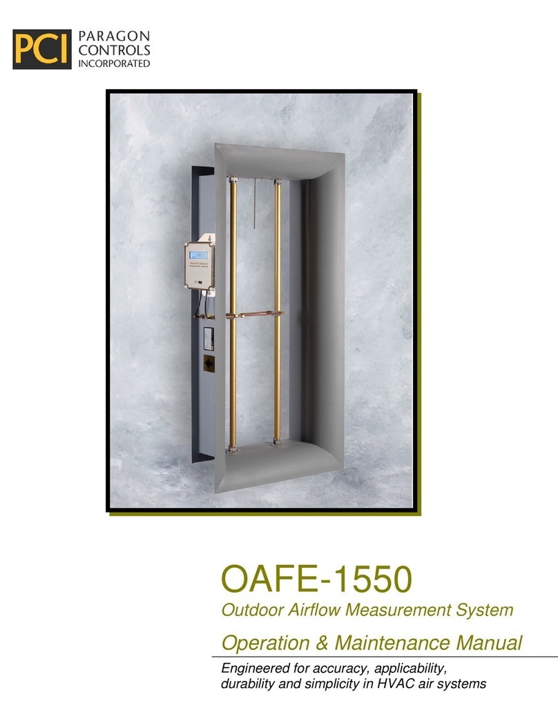
OAFE-2000
Outdoor Airflow Measurement System
Installation, Operation
& Maintenance Manual
THE SENSEABLE SOLUTION

OAFE-2000 IO&M Manual
Paragon Controls Incorporated ii Revision Level 000
TABLE OF CONTENTS
1.INTRODUCTION ..............................................................................................................................1
1.1.Description..................................................................................................................................1
1.2.Basic Operation..........................................................................................................................1
1.3.Specifications .............................................................................................................................2
1.4.Safety .........................................................................................................................................2
1.4.1.Electrical Connections ........................................................................................................2
1.4.2.Static Electricity ..................................................................................................................2
2.AIRFLOW MEASUREMENT STATION ............................................................................................3
2.1.Typical Installations ....................................................................................................................3
2.2.Installation Guidelines for Ducted Applications ..........................................................................4
2.3.Maintenance...............................................................................................................................4
2.4.Site Storage, Handling, and Spare Parts....................................................................................4
3.MTSE INSTALLATION .....................................................................................................................5
3.1.Product Installation Dimensions .................................................................................................5
3.2.Electrical Connections................................................................................................................6
3.2.1.Common Electrical Connections.........................................................................................7
3.3.Pneumatic Connections............................................................................................................10
4.MTSE CONFIGURATIONS ............................................................................................................11
4.1.Display Overview......................................................................................................................11
4.2.System Configurations .............................................................................................................12
4.2.1.Display Types ...................................................................................................................12
4.3.Display Features.......................................................................................................................13
4.3.1.Sensor Data Page Shortcut ..............................................................................................13
4.3.2.Keypad..............................................................................................................................14
5.MENU INFORMATION ...................................................................................................................15
5.1.Levels of Menus .......................................................................................................................15
5.2.Setup Menus ............................................................................................................................16
5.2.1.Operating Range Menu ....................................................................................................18
5.2.2.K-Factor ............................................................................................................................19
5.2.3.Analog I/O Configuration ..................................................................................................20
5.2.4.System Filters ...................................................................................................................21
5.2.5.Network Communications.................................................................................................21
5.2.6.Temperature Compensation & Altitude.............................................................................22
5.2.7.Alarm Options ...................................................................................................................23
5.2.8.Units and Precision...........................................................................................................25
5.2.9.ΔP Settings (Optional) ......................................................................................................26
5.3.Diagnostics Menu.....................................................................................................................27
5.3.1.Sensor Data Page ............................................................................................................28
5.3.2.System Overview..............................................................................................................29
5.3.3.Factory Defaults................................................................................................................30
5.3.4.Software Update ...............................................................................................................31
5.3.5.ScreenSaver .....................................................................................................................32
5.3.6.AutoZero Settings .............................................................................................................32
5.4.K-Factor Page Shortcut............................................................................................................33
5.5.Notification Page ......................................................................................................................33
5.6.Troubleshooting and Help Pages .............................................................................................35
ATTACHMENTS
A BACnet PROTOCOL IMPLEMENTATION CONFORMANCE STATEMENT
B MODBUS SOFTWARE CONFIGURATION PARAMETERS

OAFE-2000 IO&M Manual
Paragon Controls Incorporated 1 Revision Level 000
1. INTRODUCTION
1.1. Description
The OAFE-2000 is a packaged and specifiable outdoor airflow measuring system capable of producing
an overall ±0.5% of reading accuracy and will satisfy LEED, ASHRAE 62.1, ASHRAE 189.1, ASHRAE
170 and California Title 24 requirements for verifying the required ventilation rates or air changes per
hour.
The OAFE-2000 is designed to tackle the challenges of outside airflow measurement which is often low
velocity, loaded with particulate, and application specific. The packaged system consists of an integral
transmitter and multiple airflow elements, factory mounted and pre-piped in a casing designed for
flanged connection to ductwork, control dampers, louvers, etc. The airflow measurement station is
constructed to comply with ASHRAE Standard 111 for equal area traversing of an airflow measurement
plane.
Utilizing Paragon Controls’ full sheet metal capabilities, the OAFE-2000 can match up with almost any
new or existing ductwork, hood, or outside air opening for a seamless engineered solution. An optional
inlet bell is available for plenum applications. Application specific materials such as 316 Stainless Steel
are available where salt-air may be a concern.
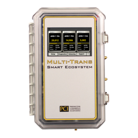
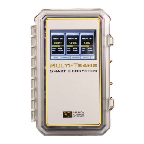
The integral (Multi-Trans Smart Ecosystem) MTSE Transmitter is a flow and pressure transmitter that
has been engineered to provide a cost-effective solution for accurate airflow measurement of up to
three systems; perfect for air handling or rooftop units requiring ventilation rate monitoring at the
outside air intake and supply and return fan/fan array airflow monitoring. The MTSE can connect to
each fan’s existing piezometer-ring airflow sensors or to field installed airflow stations; up to five flow
sensing points. The MTSE can simultaneously measure up to four additional differential pressure
sensing points such as pressure drop across filters or coils, duct static pressure, and plenum pressure.
The total (summed) airflow rate for the individual flow systems differential pressure points is indicated
on a 3.5-inch HMI touch screen.
The total airflow rate of each system is available to the BMS or local controller via dedicated field
selectable 0-10 VDC or 4-20 mA analog outputs and via field selectable BACnet®-MS/TP Master or
Modbus® RTU Slave network communications. Independent flow and pressure values for each of the
nine sensing points is also available to the BMS or local controller via network communication.
1.2. Basic Operation
The airflow measuring station produces pneumatic output signals referred to as total (high) and static
(low) pressure. These two pressure signals are piped to the MTSE where the static pressure is
subtracted from the total and the result indicated as velocity pressure (differential pressure). This
measured differential pressure is equal to the average velocity of the air stream moving through the
plane that the airflow measuring station is located in. This signal can be converted to air velocity and
flow using the following equations:
a
a
T
460
921.29
325.1
a
V
P
V
7.1096AVQ
Where:
a
Actual density of air, in lb/ft
3
(0.075 lb/ft
3
at sea level and 68°F)
a
T
= Actual temperature, in °F (default value is 68°F)
P
V
= Velocity pressure, in inches H
2
O
V = Velocity, in fpm
Q = Flow, in cfm
A = Area, in ft
2

OAFE-2000 IO&M Manual
Paragon Controls Incorporated 2 Revision Level 000
This signal is scaled and linearized before being displayed and transmitted out as a 4-20mA or 0-
10VDC signal.
The AutoZero option detects and corrects any zero offset caused by large ambient temperature
changes. The Temperature Compensation option compensates the flow and velocity signal for density
changes caused by variations in the process air temperature.
1.3. Specifications
Power Requirements 20 - 28VAC/VDC Supported Protocols BACnet MS/TP
Modbus RTU Slave
Power Consumption 8.5W, 15.3VA Max Max communication length 4000 ft. (EIA-485)
Protection Circuit Polarity Protected
Self-Resetting Fuse
Operating Temperature -20°F to 158°F
(-29°C to 70°C)
Digital Outputs (2) Open Collector Digital
Outputs
Temperature Compensated Range -4°F to 158°F
(-20°C to70°C)
Digital Inputs (2) Dry Contact Digital Inputs Storage Temperature -40°F to 257°F
(-40°C to 125°C)
Analog Outputs (4) 16-bit Analog Outputs
Field Selectable 0-10V & 4-20mA
Overvoltage and Overcurrent Protected
Enclosure Impact Resistant Polycarbonate
IP-66, NEMA 4X Rated
Fire Retardant UL 94 V-0
Analog Inputs (4) 12-bit Analog Inputs
Field Selectable 0-5V, 0-10V & 4-20mA
Dimensions 9.50" L x 5.69" W x 3.56" H
Terminal Blocks Pluggable Screw Type
16 to 24 AWG
Pressure Connections 1/4" OD Barbed
Brass Fittings
Accuracy +/- 0.25% F.S.
1.4. Safety
1.4.1. Electrical Connections
Before any electrical connections are made, ensure the POWER SWITCH is in the OFF position.
1.4.2. Static Electricity
The circuit board contains components which are susceptible to damage caused by static electrical
discharge. Should it be necessary to remove the circuit board from the enclosure, appropriate
precautions must first be taken to ensure that the operator and the circuit board are at the same
electrical potential.

OAFE-2000 IO&M Manual
Paragon Controls Incorporated 3 Revision Level 000
2. AIRFLOW MEASUREMENT STATION
2.1. Typical Installations
ROOFTOP AHU WITH RAIN HOOD
EXTERIOR MOUNTED AIRFLOW STATION
ROOFTOP AHU WITH RAIN HOOD
INTERIOR MOUNTED AIRFLOW STATION
OA INTAKE PLENUM
(BY OTHERS)
OA CONTROL
DAMPER
(BY OTHERS)
AIRFLOW
STATION
F
L
O
W
RAIN HOOD
(BY OTHERS)
OA INTAKE PLENUM
(BY OTHERS)
OA CONTROL
DAMPER
(BY OTHERS)
AIRFLOW
STATION
F
L
O
W
RAIN HOOD
(BY OTHERS)
OUTDOOR AIR PLENUM MOUNTED AIRFLOW
STATION
OUTDOOR AIR PLENUM MOUNTED AIRFLOW
STATION
LOUVER
(BY OTHERS)
OA INTAKE PLENUM
(BY OTHERS)
OA CONTROL
DAMPER
(BY OTHERS)
F
L
O
W
AIRFLOW
STATION
LOUVER
(BY OTHERS)
OA INTAKE PLENUM
(BY OTHERS)
OA CONTROL
DAMPER
(BY OTHERS)
AIRFLOW
STATION
F
L
O
W
PLENUM MOUNTED MINIMUM OUTDOOR
AIRFLOW STATION DUCTED OUTDOOR AIRFLOW STATION
OA INTAKE PLENUM
(BY OTHERS)
DAMPER
ECONOMIZER
(BY OTHERS)
OA CONTROL
DAMPER
(BY OTHERS)
LOUVER
(BY OTHERS)
F
L
O
W
AIRFLOW
STATION
OA INTAKE PLENUM
(BY OTHERS)
OA CONTROL
DAMPER
(BY OTHERS)
AIRFLOW
STATION
FLOW

OAFE-2000 IO&M Manual
Paragon Controls Incorporated 4 Revision Level 000
2.2. Installation Guidelines for Ducted Applications
The station may be installed in any duct configuration. However, the accuracy of the installation is
dependent on the flow conditions in the duct. The minimum installation requirements based upon a
uniform velocity profile approaching the duct disturbance for flow rates less than 2,500 fpm are shown
below. These are not ideal locations. It is always best to locate the station as far as possible from all
duct disturbances, with upstream disturbances being the most critical consideration.
OPPOSED BLADE DAMPERS
2D
ELBOWS
3D
FLOW
D
FLOW
2D
FLOW
D/4
FLOW
D/6
FLOW
FLOW
15° MAX
TRANSITIONS
D/6
2D
4D
FLOW
D/2
FLOW
DUCT TAKE-OFFS
FLOW
D
Notes:
Rectangular Ducts:
D =
HW4
H = Duct height W = Duct width
2.3. Maintenance
Since the sensing elements have no moving parts, only periodic cleaning may be required. The
sensing elements should be inspected for fouling of the sensing holes as part of an annual preventative
maintenance program. Installations having viscous airborne particles may require more frequent
inspection. If the sensing holes on the elements have become fouled or plugged, the following
procedure is recommended. Caution, all instruments must be isolated (removed) from the
sensing lines prior to performing the following cleaning procedure.
- Backpurging: Connect clean/dry compressed air, set at a maximum pressure of 25 psi, to
the output pressure ports (total and/or static) of the sensing element being cleaned. While
purging the sensing element, wipe the surface of the cylinder with a cloth or brush to loosen
and remove all contaminant buildup.
- Cleaning: In applications where the sensing elements are subject to viscous contaminants
it is recommended that the surface be washed with a cleaning agent. The cleaning agent
used must be suitable for use on the type of material the sensing element is constructed of
(i.e. aluminum, stainless steel, etc.)
2.4. Site Storage, Handling, and Spare Parts
The sensing elements must be stored indoors, in the original shipping package, and in a dry place.
Failure to do so may result in internal blockage of averaging chambers due to dust migration and/or
insect infestation. Although the sensing elements are not fragile by design, care must be taken not to
damage or disfigure the cylinder surface when handling and installing. Particular attention must be
given to the surface areas in which sensing ports are located. The sensing elements come as a
complete fabricated assembly. No spare parts are required.

OAFE-2000 IO&M Manual
Paragon Controls Incorporated 5 Revision Level 000
3. MTSE INSTALLATION
The MTSE is rated for either indoor or outdoor installation. It can be mounted near the
supply/return/exhaust fans reducing the pneumatic tubing runs. Since the MTSE comes standard in a
NEMA 4X Enclosure it can also be mounted in the OA intake where it may be exposed to rain/snow or
near cooling coils, providing flexibility in the mounting location. Avoid locations that are subject to high
vibration. When installed outdoors, do not install the MTSE where the display screen is in direct
sunlight.
3.1. Product Installation Dimensions
Figure 3.1 – MTSE Enclosure

OAFE-2000 IO&M Manual
Paragon Controls Incorporated 6 Revision Level 000
3.2. Electrical Connections
Figure 3.2 – Terminal Block Description
J1 – Power In The MTSE can be powered with 24VAC or 24VDC. Allowable range is 20-
28V. Pin 1 on the power supply terminal is the positive leg, however the
device is reverse polarity protected.
J2 – Future Sensor
Module Expansion
Additional remote MTSE units will be daisy-chained together to expand the
sensing capability. Currently not available.
J3 - Service
Communication
Communication pins for Factory programming. DO NOT CONNECT TO
THESE PINS.
J4 - Network
Communication
BACnet/Modbus communication pins.
J5 - Digital Inputs and
Digital Outputs
Not Used
J6 - Future Sensor
Module Expansion
Will provide power for additional MTSE sensor module units. Currently not
available.
J7 - 24VDC Output to
Temp. Transmitters
Supplies power for external temperature transmitter(s).
J8 - Analog Inputs
Analog Inputs are tied to the temperature inputs and are scaled to the
minimum and maximum values set in Temperature Compensation & Altitude
Setup Menus.
J9 - Analog Outputs
System 1 Analog Process Output is System 1 Total Summed Flow (Process
Value) of the sensors in System 1. This is scaled to the Operating Range set
in the Setup Menus where 0V or 4 mA is 0 flow and 10V or 20 mA is the
operating range.

OAFE-2000 IO&M Manual
Paragon Controls Incorporated 7 Revision Level 000
3.2.1. Common Electrical Connections
PCI recommends cable should be low capacitance, shielded 24 AWG (minimum) twisted wire for all
electrical connections. When connecting multiple MTSE units on a common communication network,
connect shielding wires together and connect only one side of the shielding wire to earth ground at the
building automation system; do not connect both ends of the shield wire to earth ground.
Figure 3.3 – Typical 1 System connection to 24VAC/DC power, 4-20mA loop-powered
temperature transmitter, analog receiving device, or network communication.

OAFE-2000 IO&M Manual
Paragon Controls Incorporated 8 Revision Level 000
Figure 3.4 – Typical 3 System connection to 24VAC/DC power, 4-20mA loop-powered
temperature transmitters, analog receiving devices, or network communication.

OAFE-2000 IO&M Manual
Paragon Controls Incorporated 9 Revision Level 000
Figure 3.5 – Typical 3 System connection to 24VAC/DC power, 0-10V three-wire temperature
transmitters, analog receiving devices, or network communication.

OAFE-2000 IO&M Manual
Paragon Controls Incorporated 10 Revision Level 000
SENSOR 4
SENSOR 5
SENSOR 2
SENSOR 3
SENSOR 1
SF-1
SF-2
RF-1
RF-2
OA-1
3.3. Pneumatic Connections
The MTSE can measure a maximum of five airflow points in up to three systems and monitor up to four
ΔP points for a total of 9 sensing points. Two pneumatic plenum-rated signal tubing lines are required
to be connected to the MTSE for each sensing point, a high (or Total) and a low (or Static) connection.
Transducers in the MTSE are numbered sequentially; therefore, all connections for System 1 must be
made in order starting at Sensor 1, and then System 2 will start immediately after the last sensor in
System 1, and so on. See label inside cover of MTSE for sensor numbering. Shown below is an
example of an MTSE configured to measure two Supply Fans, two Return Fans, and a single Outside
Air opening.
Figure 3.6 – Typical pneumatic connections to piezometer rings
on fans and outside air flow measurement station

OAFE-2000 IO&M Manual
Paragon Controls Incorporated 11 Revision Level 000
4. MTSE CONFIGURATIONS
The MTSE can be configured to measure airflow in up to 3 unique Systems and monitor up to 4
additional differential pressure (ΔP) points up to a total of 9 sensing points.
4.1. Display Overview
Shown below is a fully loaded MTSE monitoring (3) independent systems and (4) ΔPs.
Figure 4.1 – Main Screen showing 3 Systems and 4 ΔP measurement points.
1) System Number: Static text indicating the specific system number.
2) System Tagging: Custom entered tagging information for a more meaningful representation of
where measurement is taking place.
3) System Measurement: Live measurement of flow, velocity, or pressure for the System.
4) Units: Field selectable units for the System Measurement.
5) Max Operating Range: Upper limit of allowed flow measurement value. System Bar graph and
System Analog Output are scaled to this value (Max = 10V or 20mA).
6) Temperature: System Temperature reading from Input source.
7) ΔP1 Tag: Customer field entered tagging information for individual, non-System measured
differential pressures.
8) ΔP Pressure Measurement: Live measurement of individual, non-System measured pressures.
9) ΔP Alarm Value: Field adjustable alarm setpoint value for ΔP Pressure Measurement. Can be high
or low triggered setpoint.
10) Setup Menus
11) Diagnostics Menus
12) K-Factor Menu Shortcut
13) Notification: Alarms and Warning Notifications
14) (?) Troubleshooting and Support Pages

OAFE-2000 IO&M Manual
Paragon Controls Incorporated 12 Revision Level 000
4.2. System Configurations
The MTSE can be custom configured to match most applications to measure, sum, and report up to 3
systems and 4 ΔP points for a total of up to 9 sensing points, as described below:
System
Each System is defined as having all the following unique properties:
1. Single or multiple transducers to measure a single point or multiple points of differential
pressure (i.e., fan array, duct, outside air, supply air, return air, or exhaust air).
a) Multiple points are summed if measuring flow.
b) Multiple points are averaged if measuring pressure or velocity.
2. A single entry for a transducer span, piezometer coefficient, and/or area factor for flow
calculations, i.e., all fans or airflow measurement stations must be exactly the same.
3. Temperature compensation and an Analog Input for a dedicated temperature sensor input.
4. Ability to correct for “System Effect” with user defined K-Factor.
5. Selectable operating range, engineering units, and dedicated analog output signal relative to
operating range.
6. Adjustable rolling-average sample filters.
7. High and Low alarms.
In addition to the (3) Systems there are also two other sensor measurement types with their own unique
properties which are described below.
Sub System (Commonly used as 2nd OA)
Many air handling unit manufacturers are offering dual outside air intakes for greater turndown
capability. The MTSE has the ability to measure a unique and independent 2
nd
OA intake. The 2
nd
OA
flow measurement is similar to a System as explained above, but with some key differences:
1. The 2
nd
OA is limited to a sensor quantity of (1).
2. The 2
nd
OA is summed into the last System, which may or may not be System 3.
3. The 2
nd
OA has most of its own unique parameters to be entered independently from the 1
st
OA, i.e., operating range, area factor, K-factor, and alarms, but also shares the following
settings with the last system.
i. Analog Output represents summed flow value
ii. Filter
iii. Temperature
iv. Engineering units
Differential Pressure (ΔP) Points
ΔP’s are individual pressure measurements of interest. ΔP is made available on the MTSE to monitor
things such as total fan static, duct static pressure, or filter banks – to name a few examples.
ΔP’s will have no settings other than the following characteristics:
1. Same span for all ΔPs
2. Same engineering unit’s selection for all ΔPs (in pressure)
3. Individual tagging
4. Individual Alarm Trigger (High or Low)
5. Individual Alarm Value Setpoint
4.2.1. Display Types
Depending on how your MTSE was ordered, the System quantity and ΔP quantity will change the
appearance of the Main Screen. Shown below are images of a single system and a two-system
configuration with no ΔP points of measurement. If ΔP points of measurement were ordered, they will
appear at the bottom of the display similar to what is shown and described in Figure 4.1.

OAFE-2000 IO&M Manual
Paragon Controls Incorporated 13 Revision Level 000
Figure 4.2 – Main Screen for a single system and two systems.
4.3. Display Features
4.3.1. Sensor Data Page Shortcut
Touch anywhere within the dashed red box on any of the Main Screen Types (whether it is one system
or up to three systems) and the user will be taken to the Sensor Data Page which displays the flow rate
and pressure for each individual sensor. See Section 5.3.1, Senor Data Page Section for more details.

OAFE-2000 IO&M Manual
Paragon Controls Incorporated 14 Revision Level 000
4.3.2. Keypad
In most setup menus, it is necessary to enter numeric values for the settings. These values will be
entered through a popup keypad, like the one shown below:
1. Parameter Information: Indicates what parameter is currently being entered
2. Max: Maximum allowable value to be entered for the given parameter
3. Min: Minimum allowable value to be entered for the given parameter
4. Units: Displays the units for the given parameter being entered
The acceptable range of values that can be entered for a given parameter are shown in the popup
keypad as Max and Min, Item 2 and 3 in the above image. After keying in the desired value press
Enter to save the value and return to the previous menu. If you press BACK, you will be returned to the
previous menu and no values will have been saved or modified.

OAFE-2000 IO&M Manual
Paragon Controls Incorporated 15 Revision Level 000
5. MENU INFORMATION
5.1. Levels of Menus
The following is a tree view of the available menu pages on the bottom of the Main Screen (see Figure
4.1). Pressing one of these menu buttons loads a separate menu as described below. An icon with a
back-arrow key is present in every menu page in the lower left corner of the screen. This arrow key will
return you to the previous page.
NORMAL ACTIVE DISPLAY
SETUP MENU All job specific parameters and configuation
information is entered here (See Section 5.2)
DIAGNOSTICS
Sensor Data Page View flow rate, pressure data, and status
for each individual sensor
System Overview View system and parameter configuration
information
Factory Defaults
Reset MTSE to Factory Default Settings
(Caution - resetting will remove parameters
set in the field)
Software Update
If instructed by the Factory, software can
be upgraded by inserting new microSD
(uSD) card
Screen Saver Mode Toggle On or Off Screen saver
Factory Password protected factory configuration
menu
AutoZero Settings
(only available when AZ is ordered)
Initiate true AutoZero by pressing Run
AutoZero
Enable/Disable AutoZero
AutoZero Interval
(in hours upto 24)
K-FACTOR Shortcut button to K-Factor Page in
Setup Menu
NOTIFICATION Alarms and other warnings are visible here
? (INFORMATION) Company information and software revision
are visible here
Troubleshooting information is also visible
with the right arrow

OAFE-2000 IO&M Manual
Paragon Controls Incorporated 16 Revision Level 000
5.2. Setup Menus
In each of these menus, the parameters for Systems 1, 2, and 3 (description of a System can be found
in Section 4.2) will be configured. For example, if the user is in the Operating Range Menu the
operating range for Systems 1, 2 and 3 will be set in this page. Only Systems that have been
configured in the Factory menu will be displayed in the Setup Menus. Therefore, the pages in the
Setup Menus may look different from your setup if the sensor quantities were only entered for one or
two systems at the Factory.
All Setup Menu pages will write each System’s parameters to internal memory and also be backed up
on the microSD card. Some settings are not System specific and will be applied to all (3) Systems.
These settings are as follows:
a) Altitude and Altitude Units
b) Temperature Units
c) Communications
Each page has a question mark icon (?) in the bottom right corner for Help Dialogue. Selecting this
icon will navigate to a help screen detailing the parameters and their functions of the previous page.
Shown below is the Setup Menu Main page.
The structure of the Setup Menu is shown in the flow chart below. A detailed explanation of each Setup
Menu item is described in the following subsections.

OAFE-2000 IO&M Manual
Paragon Controls Incorporated 17 Revision Level 000
SETUPMENUS
1. Operating Range
Enter Tagging Information for each system
served
Toggle Select Area Type either Area or
Piezometer for each system
Enter Area or Piezometer Coefficient
for each system
Enter Operating Range for each system;
Max value that represents 100% of output
For Piezometer Coefficients that incorporate
a Standard Density term, toggle
Std. Den. to Incld
2. K-Factor
Enter Balancer and MTSE flow
measurements to calculate a K-factor
Or enter K-factor directly
3. Analog I/O
Toggle select System Process Output
0-10V or 4-20mA for each system
Toggle select System Temperature Input
0-5V, 0-10V, or 4-20mA for each system
4. System Filters Enter total Number of Samples for rolling
average calculation for each system
Enter Sampling Interval Time (time in
seconds between samples) for rolling
average calculation
5. Network
Communications
Toggle select between BACnet MS/TP
Master or Modbus RTU Slave
Toggle select available Baud Rate
Enter the MAC Address or Modbus ID Enter Instance Number (BACnet only)
6. Temperature and
Altitude
Toggle select where Temp Input will be
obtained between Fixed, Variable, or
Network for each system
If Fixed temp, enter Temp in last column.
If Variable, enter min and max Temp for min
and max analog input for scaling
Toggle select between Altitude or Barometric
pressue for density correction
If Altitude selected, enter Elevation in feet; if
Barometric selected enter Pressure in in.Hg
Toggle select Termperaure Units between
degrees F or C
7. Alarms
Toggle Enable or Disable Alarms for each
system
Enter Low and/or High Alarm setpoint value
(in same units) to be compared to an
individual sensor's value (0 is Off)
Enter Alarm Delay value; amount of time in
seconds before alarm is triggered
Enter Lockdown Percent (of Operating
Range) for each system; a zero value will
be indicated when below this percentage
Enter a Lockdown Delay value; amount of
time in seconds before a zero value is
triggered
8. Units and Precision
Toggle select between Measurement Type:
Std. Flow, Act. Flow, Std. Velocity, Act.
Velocity, or Pressure for each system
Toggle select Units of measure
corresponding to the Measurement Type
Toggle select the Decimal Point location for
significant decimal figures for each system
9. ΔP Settings
(only if ΔP is ordered)
Enter ΔP Tagging information for each
ΔP point
Toggle select Alarm trigger mode for each ΔP
point: Off, High Alarm, or Low Alarm Enter Alarm Setpoint value (in same units)
Toggle select ΔP Units of measurement

OAFE-2000 IO&M Manual
Paragon Controls Incorporated 18 Revision Level 000
5.2.1. Operating Range Menu
This menu allows the user to modify the fields shown and described below. This page may look
different from your setup if the sensor quantities were only entered for one or two systems. Navigate to
this menu from the Main Screen by pressing Setup » 1. Operating Range.
Tagging Information
Selecting this box will provide a keypad popup to allow entry of unique System tagging information.
The tagging information will be displayed on the Main Screen and any other place indicating System 1,
System 2, or System 3 Tagging in the Setup Menus. Twelve characters can be entered as the System
tag.
Area Type
Allows user to toggle between flow calculation method for either Area or Piezometer ring equations.
Area should be selected if the MTSE is connected to a flow station or flow sensors with known cross-
sectional area. Piezometer should be selected if connected to a fan’s piezometer ring that has a
manufacturer-provided fan coefficient.
Area/Piezometer Coefficient
Allows user to enter or modify an existing Area Factor if Area is selected in Area Type. The cross-
sectional area of the flow station or duct is used to determine volumetric flow in the MTSE. If a new
Area Factor value is entered and causes the previous entered Operating Range value to exceed the
new minimum or maximum calculated full-scale range, the new area factor will be set, and operating
range will be the new full-scale maximum.
If Piezometer is selected in Area Type, allows user to enter a manufacturer-specified fan coefficient
when connected to a piezometer ring. See Standard Density below for different ways manufacturers
present fan coefficients.
Operating Range
Allows user to enter a value which will represent 100% of the process output signal also referred to as
Max on the Main Screen page. Touching this box will bring up the Keypad which identifies the
maximum and minimum values that can be entered. The maximum value is calculated at full scale
transducer span, and the minimum value is calculated using the low limit value entered by the Factory
(Operating Range Low Limit Default = 5% of maximum Vp value).
Table of contents
Other PCI Measuring Instrument manuals
Popular Measuring Instrument manuals by other brands

Agilent Technologies
Agilent Technologies E8363BU/CU-068 Installation note

MULTISPAN
MULTISPAN VOLT-19N operating manual

Ambco
Ambco 2500 user manual

Ludlum Measurements
Ludlum Measurements 3003i manual

Precision Digital Corporation
Precision Digital Corporation ProVu PD6001 instruction manual

PCB Piezotronics
PCB Piezotronics IMI SENSORS M625B02 Installation and operating manual