pcl NEXUS Series User manual

76411 Issue 2 www.pclairtechnology.com
NEXUS Generator & Multi-head Inflator User Manual
Safety Guidelines
This manual contains information that is very important to know
and understand. This information is provided for safety and to
prevent equipment problems. To help recognise this information,
observe the following symbols.
Danger indicates an imminently hazardous
situation which if not avoided WILL result
in death or serious injury.
Warning indicates a potentially hazardous
situation which if not avoided, COULD
result in death or serious injury.
Caution indicates a potentially minor or
moderate injury.
Notice indicates important information,
that if not followed, may cause damage to
equipment.
Unpacking
After unpacking the unit, inspect carefully for any damage that
may have occurred during transit.
Do not operate unit if damaged during
shipping, handling or use.
General Safety Information
The operator of this product must take the necessary precautions
to prevent the level of danger indicated by these symbols. The
operator is required to read and understand this instruction
manual and all safety warnings, labels etc.
Any employer allowing the use of this product in their field of work
must distribute this instruction manual to all users. The employer
must also ensure all users read, understand and follow the
instructions as described in the manual, safety warnings, labels,
etc.
Please read and save these instructions. Read carefully before attempting to assemble, install, operate or maintain the product described.
Protect yourself and others by observing all safety information. Failure to comply with instructions could result in personal injury and/or
property damage! Retain instructions for future reference.
Image shown is PCL standard decal.
Actual decal may vary by individual part number.
Read and understand all safety warnings
and instructions before operating this
product. Failure to read and follow all
safety warnings may result in serious
personnel injury or death. Property
damage and/or product damage may also
occur if all warnings are not followed.
1. Do not expose the product to flammable gases,
vapours or fumes
2. Do not store flammable gases in or near this product
3. Never use flammable or toxic solvents to clean the
product or any of the unit's parts
4. Never remove or alter any safety warning labels, tags,
etc. located or provided with product.
5. Follow all directions for maintenance.
The use of other than genuine PCL
replacement parts may result in reduced
equipment performance. Repairs must be
performed by authorised repair personnel,
otherwise the warranty will be void.
PART NUMBER
SERIAL NUMBER

NEXUS Generator & Multi-head Inflator user manual
www.pclairtechnology.com
General Specifications
This Equipment also complies with the EC directives:
2004/108/EC (EMC directive)
confirmed by report No.10655/TR/1
73/23/EEC (LOW Voltage Directive)
as amended by 93/68/EEC
Accordance with IEC/EN 61010-1:2001 confirmed by
report No. TTR-004115-18-00
Guidelines
In order to provide a trouble free operation it is necessary to
connect the power supply from the main switchboard with a MAX
3amp fuse/RCB protection device. This must be grounded.
The circuit breaker should be marked as the disconnecting device
for the equipment.
The compressor producing the air should have the necessary
water and dirt filtration, to minimise accumulation of debris at the
inflator line filter strainer.
For efficient tyre inflation, ensure that the air supply is 10 psi, 0.7
bar or 70kpa above the intended maximum inflation range.
Inside installations
Use 3 pin connecting plugs or 2 pin + Earth with the Earth Ground
wire installed on electrical infrastructure.
The unit is designed to run with the earth connection installed.
"According to Class 1 - Basic insulation in conjunction with
protective Earthing"
Calibration & Accuracy
The accuracy of our digital units when released from our factory is
that:-
The maximum permissible error (MPE) = 0.08 bar
Each unit, before release, is checked and calibrated on test
equipment that has accuracy traceable to a UKAS Laboratory No.
0221 referenced to certificate 0029346.
NEXUS
variant
Max inlet
supply
Min inlet supply Recommended
supply
Max inflation
pressure
Min inflation
pressure
Display
resolution
Units of
measurement
NEX2/MQ 145psi/10bar/
1000kPa
130psi/9bar/
900kPa
14.5psi/1bar/100kPa
above max set
pressure of inflator
90psi/6.3bar/
630kPa
4psi/0.3bar/
30kPa
1psi /0.1bar/
10kPa
psi/bar/kPa
NEX4/MQ 145psi/10bar/
1000kPa
130psi/9bar/
900kPa
14.5psi/1bar/100kPa
above max set
pressure of inflator
90psi/6.3bar/
630kPa
4psi/0.3bar/
30kPa
1psi /0.1bar/
10kPa
psi/bar/kPa
NEX6/MQ 174psi/12bar/
1200kPa
145psi/10bar/
1000kPa
14.5psi/1bar/100kPa
above max set
pressure of inflator
160psi/11bar/
1100kPa
4psi/0.3bar/
30kPa
1psi /0.1bar/
10kPa
psi/bar/kPa
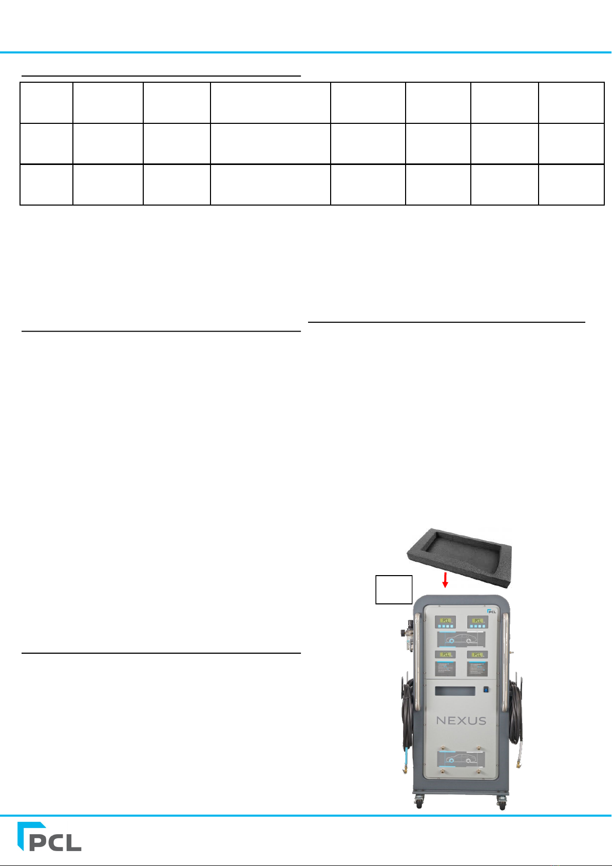
Pre-use installation elements
Upon unpacking of the unit please note there is hardware that will
need installing on the machine before operation can commence.
There is a foam insert (fig1) that accompanies the NEXUS where
the following components will be packed:
Four hoses (DS68)
Four hose brackets
Gauge dial (Forms part of the ATC12)
ATC12 (+ATF12 for NEX6 models) regulator mounting screws and
washers.
UK power lead (N2S23)
EU power lead (N2S24)
US power lead (N2S25) - supplied with 120v US variants only
Any hoses that can not be packaged into the foam insert will be
strapped to the cabinet with shrink wrap.
Fig 1

NEXUS Generator & Multi-head Inflator user manual
www.pclairtechnology.com
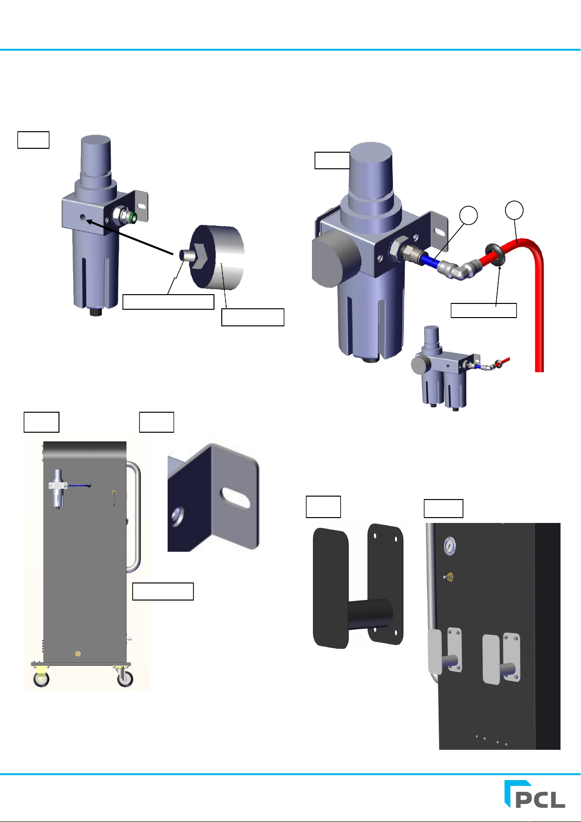
1. Install filter-regulator (ATC12).
Remove filter-regulator unit and dial gauge from packaging and
apply PTFE tape to the dial thread before screwing into the unit.
2. Installation of filter-regulator mounting brackets
Locate holes on side of cabinet and mount the brackets to these
using the screws and washers provided (fig2). The two slotted
bracket mounts are already pre-attached to the filter (fig3).
3. Attachment of pneumatic pipe to the filtration unit.
Pipe A is attached to the right hand side of the filter-regulator via a
push in fitting.
4. Installation of hose mounting hooks
There are two mounting hooks (Fig 5) that need mounting on each
side of the cabinet. Screws and washers are provided. Simply
locate mounting holes on the side of cabinet and install (Fig 6)
Front
Fig 4
A B
Grommet
Fig 1
Dial
Fig 2
Re-apply PTFE tape
Fig 3
Fig 5 Fig 6
N6 Version
NEXUS Generator & Multi-head Inflator user manual
www.pclairtechnology.com
General Specifications
System set-up instructions
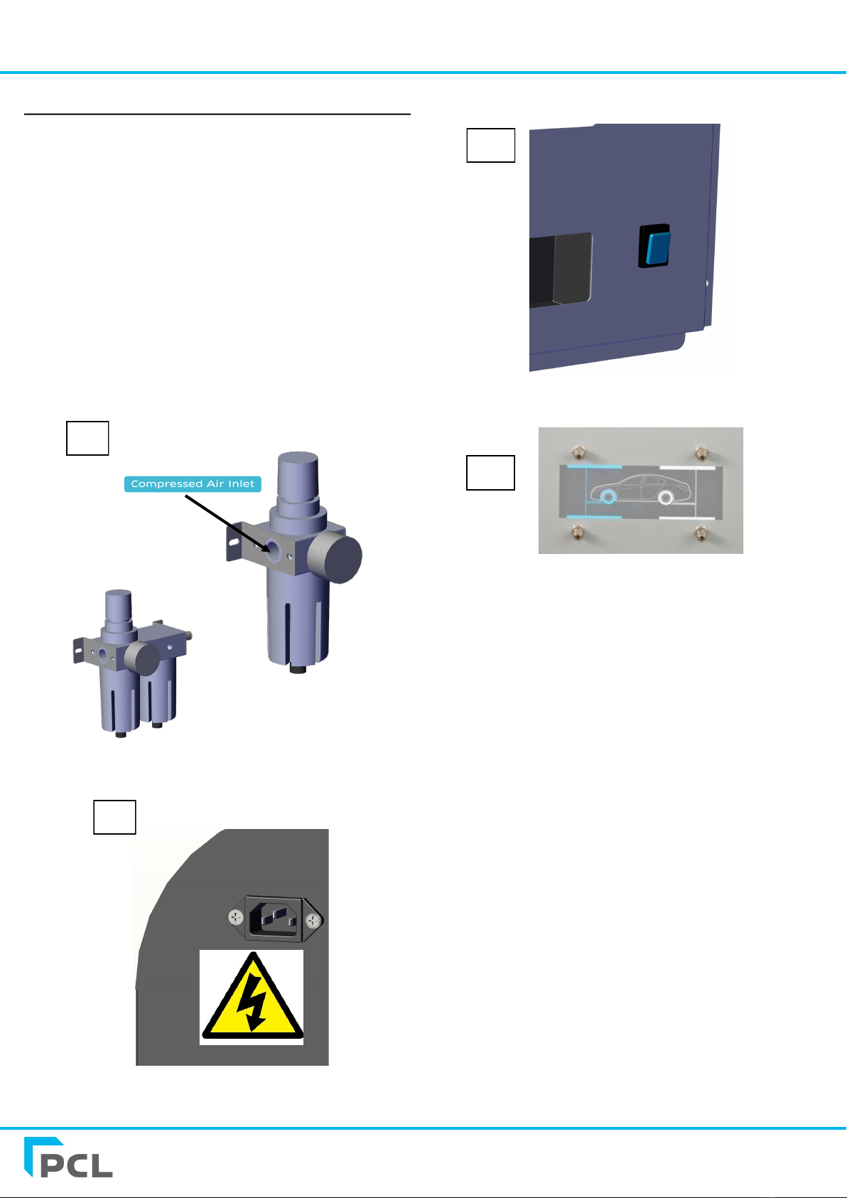
1. Connect to air supply by screwing your chosen adaptor to the
Rp 1/4 fitting (1/4 NPT for US versions) into the compressed air
inlet port, See Fig. 7. Then connect your air supply coupling end
to the adaptor. Please note the N6 version has a combination
filter unit.
2. Connect the mains power lead to the IEC socket at the back of
the unit cabinet as shown in FIG 8.
3. Turn on/off switch to the ‘on’ position shown in FIG 9.
4. Locate hose output quick connect couplings at the bottom of
the unit and connect all four hose adaptor ends to these shown in
Fig 10. Ensuring the blue coded hoses are connected to the blue
terminals and the white coded hoses to the white terminals.
N6 Version
Fig 7
Fig 8
Fig 9
Fig 10

NEXUS Generator & Multi-head Inflator user manual
www.pclairtechnology.com
Operation
Switch on the Inflator Generator by pressing the button on the front of
the unit, shown in Fig. 9.
Following this the LCD display check process will run. During this
process, the slave controller will then show ‘SYN’ and these will
synchronise with the master controllers.
= Increase target set pressure
= Decrease Set pressure
= Commence flat tyre start up
= Top off or Purge Mode select
The Nexus multi-controller is configured to have 4 controllers, these
are set in pairs, 1 for the Front and 1 for the Rear of the vehicle.
There are 2 Vertical pairs and each Vertical pair is configured to be a
Master and Slave controller.
Adjustment of pressure on each pair is controlled by the Master and
the Target pressure is also simultaneously set on both.
Adjustment of tyre pressures
Set the Tyre pressure with the + and –buttons on the top left for the
front two tyres, and top right for the rear two tyres.
This sets the target pressure
simultaneously on the both paired
controllers.
1. Select Inflation Mode using the Purge or Top Off/Standard
cycle button.
To Select the Inflation Mode press ‘once’ to view current
setting, to change to the alternative mode, this button is
pressed twice before the LCD screen returns to the Set
pressure display.
For Purge Mode the display will show the symbol shown
on the left (Default at Machine start up).
For standard inflation / Top Off Mode the Display will show the symbol
shown on the left.
For purge cycle follow the below
steps
Follow the below sequence for purging the tyres.
1. Set Target pressures for front and rear wheel.
2. Set desired mode for ‘purge’ operation.
3. Connect the hoses marked with Blue indicator to the front
two tyres and connect the hoses marked with white
indicator to the rear two tyres.
4. Auto deflation will commence with the default 2 purging
cycles as soon as the delivery hoses are connected to the
tyres.
The inflation cycle is complete when the axle has both LCD dis-
plays showing ‘END’ and an audible buzzer is heard. The Complet-
ed front or rear axle hoses to tyres can be removed. The remain-
ing axle will continue to complete its remaining cycles inde-
pendently, until the both show ‘END’ and the audible buzzer is
heard.
Note: If the one of the tyre has reaches the target pressure 1st on
the same axle, the audible warning will wait until the 2nd tyre is
also at the END condition.
For standard inflate follow the
below steps
1. Set Target pressures for the front and for the rear wheels.
2. Set desired mode for operation ‘Top off’
3. Connect the hoses marked with Blue indicator to the front
two tyres and connect the hoses marked with white
indicator to the rear two tyres.
4. Auto inflation will commence as soon as the delivery hoses
are connected to the tyres.
The inflation cycle is complete when the axle has both LCD
displays showing ‘END’ and an audible buzzer is heard. The
Completed Front or rear axle hoses to tyres can be removed. The
remaining axle will continue to complete its remaining cycles
independently, until the same ‘END’ and the audible buzzer is
heard.
Purging or Top/off of Motorcycle
wheels
Follow procedures above, the unused hoses may be left connected
to the generator. If the Device is to be used to inflate 2 flat tyres,
the 2 spare hoses will need to be disconnected from the generator
During a Top off or Purge procedure, at any time the cycle can be
paused by pressing the + or - buttons, the display will show the
current pressure and l l (pause symbol).
Press + or –to recommence the cycle.

NEXUS Generator & Multi-head Inflator user manual
www.pclairtechnology.com
Flat tyre inflation
It will be observed that if some of the wheels are not inflating this
will show a ‘0’ (Zero) on the display. Press flat tyre to initialise the
flat tyre inflation pulses.
If all the wheels are flat, the user must press the Flat tyre key on
both axles.
To inflate a number of flat tyres with unused hoses only, the
unused hoses must be disconnected to avoid hose ‘snaking’ from
the discharging high pressure N2.
Note: Always ensure that any replacement hose connectors are of
the “Open end” type
Emergency stopping
Top pause/stop the inflation / deflation cycles press either the + or
- button together. This will display a pause symbol. To re-start
press the + or - button again.
To adjust N2purge parameters
Number of Purge Cycles NPC
Over Pressure Limit OPS
Lower Pressure Limit LPL
These can be adjusted if required by the operator by:-
1. Turn the unit on and off to restart the ‘set up’ process
2. When you see ‘PCL’ displayed on both top left and top right
controller screens press the + and - buttons simultaneously
3. Press the + button until you see ‘8’ displayed on the
screens
4. Enter this by pressing the flat tyre button on both screens
5. The screen at this stage should display NPC. This is the first
of the four parameter settings. These parameters may be
scrolled up and down to view by pressing the + or -
buttons. The three parameters are fully defined in (1)
Parameters.
6. To access any of the parameters, press flat tyre, this will
open up the parameter contents, adjust values using the
(+/-) buttons and save value chosen by pressing the flat
tyre button.
7. To exit out of any parameter press the far right button
once, this will return you to the set default press.
(1) Parameters
Definition PCL standard settings
npc Number of purge cycles 2
ops Over pressure setting 0 psig/bar or set pressure
lpl Lower pressure limit 10 % of target pressure
npc is adjustable between 1 and 5 cycles = increase cycles to
improve N2 tyre purity. On N6 models ONLY when the desired
inflation pressure is above 60psi/4.1bar you only require 1 purge
as standard to achieve an acceptable purity level while increasing
inflation times.
ops is adjustable between 0 and 29 psig/2.00 bar = allows the
inflation pressure to go beyond the set pressure by the value
assigned, this may be used to compensate for a reduced number
of N2 cycles .
lpl is adjustable between 10% to 50% and represents lower limit
for purging. For tyres with higher set pressures the low pressure
threshold can be increased to reduce time, and can be coupled
with an increased number of N2 cycles.
Adjusting tank pressure
tnp is adjustable for the NEX6 only. The NEX6 is factory set at
9bar/130psi. If your max inflation pressure is 8bar/116psi or less
you DON’T need to change the TNP. Always remember that the
Tank Nitrogen pressure (TNP) MUST be at least 1 bar / 14.5psi
higher than the max inflation pressure. For example if you are
inflating to 9bar/130psi your TNP MUST be set at 10bar/145psi. To
achieve the TNP pressure the input pressure (seen on the
regulator on the side of the unit) must be 1 bar higher e.g.
11bar /160psi.
In order to do this you must first remove the
top back plate from the rear of the unit using
an Allen key. You will then see an LCD head
assembly and buttons. Follow the procedure:
1. Turn the unit off and back on again using the front on/off
switch.
2. When the unit is running its start up checks you will see
‘PCL’ on the screen, press the far right button within 2
seconds of seeing PCL.
3. ‘L1’ should be visible on the screen. Press the + button until
you see ‘L9’ on the screen.
4. Press the flat tyre button to enter into it
5. Press the + button until you can see TNP displayed.
6. Press flat tyre button to enter into it.
7. The screen should display 8bar/116psi
8. If you want to reduce or increase this tank set pressure
simply press the + or - button to reach your target.
9. Once you have reached your target press the flat tyre
button to save it.
10. Press the far right button three times to enter out of
parameters and back into the start up process screen.

NEXUS Generator & Multi-head Inflator user manual
www.pclairtechnology.com
For inspection and checking of
the actual tyre pressure:
1. Simultaneously depress + and - keys together (long
sound tone will be heard), then press the start button 5
times
2. Tyre pressure will now display pressure resolution to 0.01
bar. User may then compare pressure accuracy to test
apparatus (Note: Unit will not function as tyre inflator)
3. By pressing any button, the unit will resume to normal
screen operation.
Calibration & Accuracy
The accuracy of our digital units when released from our factory
is that:-
The maximum permissible error (MPE) =
0.08 bar.
Service / Maintenance
There is no requirement to service the following items:
1. Pressure Transducer
2. Electric Control Board
If these are faulty they can only be
replaced by a competent person.
Please refer to an Authorised
dealer.
Periodically
Check the hose.
Check the tyre connector.
Remove air input supply and tyre hose from the head.
Unscrew captive sintered filters from filter housings and
clean or replace.
Working safety instructions
Since the unit is not explosion-proof, the device should not be
installed in areas where explosions are possible. Consideration
must be given to the requirements relative to Hazardous Area
Standards for your region or country.
The unit is designed and built to the relevant basic health and
safety requirements of the EC.
This product can be dangerous if used
improperly. Children should not be
allowed to use this equipment, as
incorrect setting can allow tyre to be
over inflated and a subsequent tyre
burst/explosion can occur!
Each person who is involved with installation, start-up,
maintenance and the operation of the unit must read and
understand the complete operating manual.
The PCL tyre inflators are exclusively approved for the
dispensing of air/N2. Each use which doesn't follow this
purpose as well as modifications to the product will be
deemed to be improper use. The manufacturer is not liable
for damages caused by improper use, the risk lies solely
with the user.
Proper use of the product also implies the
observance of the manufacturers
instructions with regard to installation,
start-up, operation and maintenance.
All works concerning installation, start-up,
adjustment and maintenance must be
made by qualified staff. For the operation
of this tyre pressure inflator the local
safety and accident prevention rules must
be observed in all cases.
High Pressure air is stored within the
system.
Do not exceed the maximum air input
pressure.
Do not operate this product if tired or
under the influence of medication, drugs
or alcohol.
To avoid the risk of personal injury,
especially to the eyes, face or skin DO
NOT direct the air/N2stream at any
person.
NEXUS Generator & Multi-head Inflator user manual
www.pclairtechnology.com
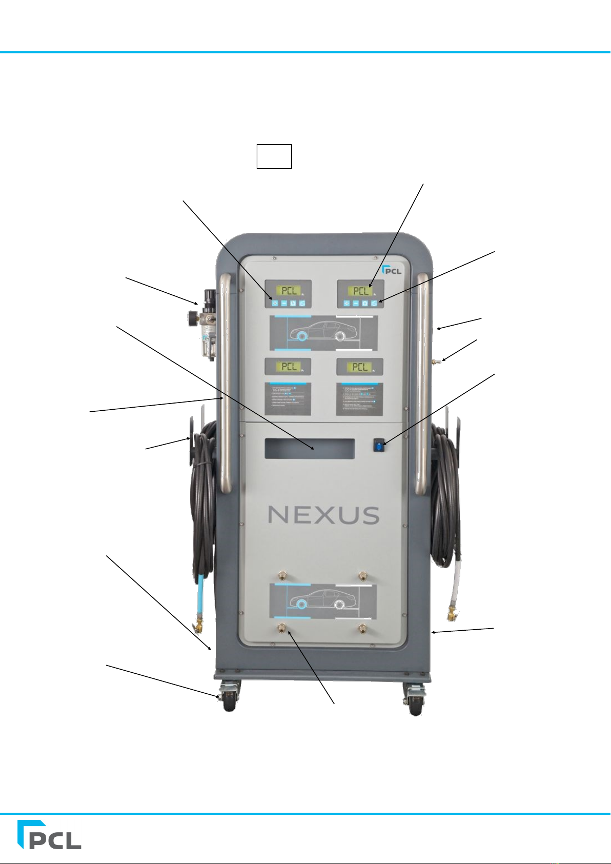
Filter-regulator unit
LCD Display
Valve cap tray
Hose hooks
Output hose connections
4 individual
exhausts
90mm castors
Rear tyres control
panel
On/Off switch
Auxiliary port
N2 Tank pressure
Nitrogen purity test point
Handles
Unit view
Fig 14
Front tyres
control panel
NEXUS Generator & Multi-head Inflator user manual
www.pclairtechnology.com
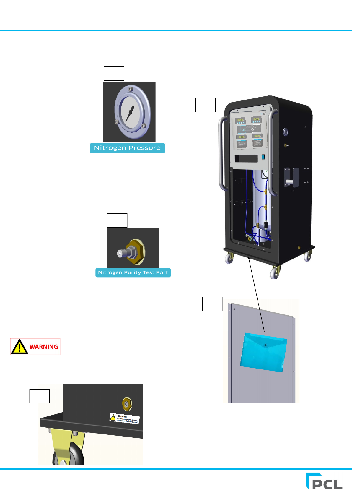
FOR TRAINED ENGINEERS ONLY
If required you can locate the system installation and internal
wiring diagrams in a document wallet. To do this you must
disconnect the air supply to the unit. Remove hex head screws
using a 5mm Allen key on all the bottom panel screws. Then
disconnect the nylon pipe from the 6 way manifold block situated
on the bottom of the panel in Fig 18.
Fig 15
Fig 17
Fig 18
Fig 19
Nitrogen Pressure Gauge
This is located on the side of the unit and indicates the Nitrogen
tank pressure contained within the unit (Fig 15).
Nitrogen Purity Test Port
This is located on the side of the unit below the Nitrogen Pressure
Gauge and is designed to identify the purity of Nitrogen being
produced by the machine. To identify the purity of Nitrogen being
produced simply remove the valve cap and push the connector on
a PCL Nitrogen Analyser unit (N2A001) which will automatically
give you a purity readout.
Fig 16
Auxilliary Port
This is located on the bottom of the left hand side of the unit. This
is only designed for use when other equipment needs to be used
with the unit. For example to connect a ‘closed end’ MK3 airline
gauge for manual inflation or to connect the unit to a receiver
tank. The auxiliary port is not connected to the control panel.
Please note that the Nitrogen pressure (Fig
15) MUST be drained before removing the
auxiliary port to connect other equipment.

NEXUS Generator & Multi-head Inflator user manual
www.pclairtechnology.com
Problem Possible Cause Solution
No display No power connected Switch power on
No inflation process Tyre is below 3 psi
Faulty connector
Press flat tyre button
Replace faulty connector
Buzzer does not sound Buzzer volume has been turned off
Buzzer is damaged
Turn buzzer on
Replace buzzer
Inflation process starts but does
not complete
Low or no supply pressure
Leaks exist
Check supply pressure
Confirm leaks do not exist
Supply pressure leaks out input Input and tyre hoses are incorrectly reversed Ensure input connection is to offset port, tyre
connection is central between input and exhaust
Inflating or deflating is very slow Check that mesh filters under input and output
port fittings are blocked
Clean and or replace mesh filters
Connector will not seal to the
tyre stems
Connector worn Replace connector
Connector leak while not
connected to tyres
Connector worn Replace connector
E1 Unstable or insufficient supply pressure Check the supply pressure
E4 Small volume, caused inflator to check pressure
> 2bar / 29psi over target pressure
Check hose is not kinked or blocked, ensure a OPEN
END connector is installed
E5 Inflator started under pressure i.e. is connected
to tyre or a CLOSED END connector is being used
Remove hose from tyre and allow inflator to reset
Change connector to OPEN END type
E6 Pressure sensor drift out New sensor required - Refer to authorised repairer
E8 Pressure sensor disconnected from PCB or faulty New sensor required - Refer to authorised repairer
E9 Pressure sensor failure - high New sensor required - Refer to authorised repairer
E10 Under voltage Check power supply
E11 Over voltage Check power supply - Refer to authorised repairer
E12 Checksum corrupted New PCB required - Refer to authorised repairer
E13 Lost or corrupted calibration settings New PCB required - Refer to authorised repairer
E14 Count issue New PCB required - Refer to authorised repairer
E17 Calibration settings corrupt Recalibrate unit - Refer to authorised repairer
E18 Runtime error New PCB required - Refer to authorised repairer
E19 Touch screen error New PCB required - Refer to authorised repairer
E20 - E23 Start-up sequence error(s) New PCB required - Refer to authorised repairer
E24 PSA count/run hours error New PCB required - Refer to authorised repairer
E25 N2 count/run hours error New PCB required - Refer to authorised repairer
E26 Tank sensor under range New sensor required - Refer to authorised repairer
E27 Tank sensor over range New sensor required - Refer to authorised repairer
E28 Signature mismatch / PCB error New PCB required - Refer to authorised repairer
E35 Communications failure Switch machine off and back on - if error still
persists please refer to authorised repairer.
Trouble Shooting Guide/Error Messages
NEXUS Generator & Multi-head Inflator user manual
www.pclairtechnology.com
PCL LIMITED WARRANTY
PCL warrants the components of each unit to which this Limited Warranty applies against defects in materials and workmanship for
a period of twelve (12) months from date of sale (as evidenced by bill of sale or equivalent) or for a period of eighteen (18) months
from date of shipment from PCL manufacturing facility (identifiable by the serial number and noted on original bill of lading from
the manufacturing facility), whichever period is shorter. During this warranty period and subject to the conditions set forth in this
statement, PCL will, at its option, repair or replace component parts that were defective at the time of shipment from PCL
manufacturing facility, subject, however, to the following specific EXCLUSIONS: hoses and connections.
Repair or replacement will not extend the warranty period.
Customer must give PCL timely notice of any warranty claim by contacting an authorized PCL service centre. Claims must be
accompanied by (1) evidence, by a bill of sale or equivalent, which clearly establishes date of purchase of the unit and (2) the
serial number, found on the unit. Customers must properly pack parts in their original or equivalent packaging, prepay shipping
charges, and insure the shipment or accept the risk for loss or damage in shipment. Return shipment to customer will be freight
collect unless otherwise agreed. For service at a customers location, customer will be charged the then prevailing service rates .
The Limited Warranty applies to PCL manufactured units only. Items listed in the applicable operators manual under routine
maintenance are not covered by this or any other warranty. Failure to complete maintenance as stated in any applicable
maintenance schedule will void the Limited Warranty. The Limited Warranty is expressly conditioned upon proper and normal use
and service of the unit and upon strict compliance by customer with all of PCL instructions and recommendations for installation,
operation and maintenance. The Limited Warranty does not apply to the unit or parts that are damaged or become defective due to
improper handling, maintenance, storage, use, or operation, and does not cover ordinary wear and tear, corrosion, or erosion.
THE LIMITED WARRANTY SET FORTH IN THIS STATEMENT CONSTITUTES PCL'S SOLE WARRANTY FOR THE UNIT AND
THE REMEDIES SET FORTH HEREIN CONSTITUTE CUSTOMERS SOLE REMEDIES FOR BREACH OF WARRANTY. THIS
LIMITED WARRANTY IS IN LIEU OF ALL OTHER WARRANTIES, EXPRESS OR IMPLIED, IN FACT OR BY LAW,
INCLUDING WITHOUT LIMITING THE GENERALITY OF THE FOREGOING, ANY WARRANTY OR MERCHANTABILITY OR
FITNESS FOR A PARTICULAR PURPOSE.
Determination of the suitability of the unit for the use contemplated by the customer is the sole responsibility of the customer. PCL
shall not, under any circumstances, be liable in contract, tort or otherwise (including negligence and strict liability) for indirect,
special, incidental, or consequential damages, and PCL's total liability shall not exceed the net purchase price for the unit. PCL shall
be excused for delay or inability to perform obligations due to events beyond its reasonable control.
CUT HERE
Mail to:
Warranty Department
PCL
Holbrook Rise
Holbrook Industrial Estate
Sheffield
S20 3GE
United Kingdom
Warranty Registration
Please complete and mail this form to activate warranty
Or visit us at www.pclairtechnology.com
Name ________________________________________ Title _________
Company Name ______________________________________________
Type of Business _____________________________________________
Address ____________________________________________________
City _______________ County _______________ Post Code __________
Telephone ___________________________________________________
Part Number ____________________ Serial No ____________________
Purchased From ______________________________________________
Purchase Date _________________________
Calibration Certificate
Each unit, before release, is checked and calibrated on test equipment that has accuracy
traceable to Druck pressure indicator S/N2329290.
The Druck unit is referenced to Certificate 0029346 issued by UKAS Laboratory No. 0221.
This accuracy exceeds EC Directive 86/217/EC and BS EN 12645:1999 (MPE = 0.08 bar).
This Equipment also complies with the EC directives:
2004/108/EC (EMC directive) confirmed by report No.10655/TR/1
73/23/EEC (LOW Voltage Directive) as amended by 93/68/EEC
Emission: EN 61000-6-3:2007 Electromagnetic compatibility Generic standards
EN 55016-2-3:2006; EN 55016-2-1:2004; EN 55014-1:2006
EN 61000-3-2:2006; EN 61000-3-3:1995 +A1+A2
Immunity: EN61000-4-2:1995+A1+A2:2001; EN61000-4-4:2004; EN61000-4-5:2006
EN61000-4-6:1996+A1:2001; EN61000-4-11:2004
EN61000-4-8:1993+A1:2001
Inflator Head Location
Set Pressure Top
Left
Top
Right
Bottom
Left
Bottom
Right
2 BAR / 29PSI
5.5 BAR / 80PSI
PURITY
PART NUMBER
SERIAL NUMBER
TESTED BY
DATE

76411 Issue 2 www.pclairtechnology.com
Orientierungshilfen zur Sicherheit
Diese Bedienungsanleitung enthält wichtige Informationen, die
bekannt sein und verstanden werden muss. Diese Informationen
dienen der Sicherheit und der Vermeidung von Problemen mit dem
Gerät. Sie erkennen diese Informationen an den folgenden
Symbolen.
'Gefahr' weist auf eine unmittelbar
gefährliche Situation hin, die bei
Nichtvermeidung zum Tod oder zu
schweren Verletzungen führt.
'Warnhinweis' weist auf eine potentiell
gefährliche Situation hin, die bei
Nichtvermeidung zum Tod oder zu
schweren Verletzungen führen könnte.
'Vorsicht' weist auf eine potentielle
mittelschwere oder geringe Verletzung
hin.
'Hinweis' weist auf wichtige Informationen
hin, deren Nichtbeachtung zu Schäden am
Gerät führen kann.
Auspacken
Prüfen Sie das Gerät nach dem Auspacken sorgfältig auf eventuelle
Transportschäden.
Nehmen Sie das Gerät nicht in Betrieb,
wenn es beim Versand, Transport oder
Gebrauch beschädigt wurde.
Allgemeine
Sicherheitsinformationen
Der Bediener dieses Produktes muss die notwendigen
Vorkehrungen ergreifen, um die durch diese Symbole angezeigten
Risiken zu vermeiden. Der Bediener muss diese
Bedienungsanleitung sowie alle Sicherheitsetiketten, Warnhinweise
usw. lesen und verstehen.
Jeder Arbeitgeber, der den Einsatz dieses Produktes in seinem
Arbeitsbereich gestattet, muss diese Bedienungsanleitung an alle
Benutzer ausgeben. Der Arbeitgeber muss auch dafür sorgen, dass
alle Benutzer die Anweisungen der Bedienungsanleitung, die
Etiketten, Warnhinweise, usw. lesen, verstehen und befolgen.
Bitte lesen Sie diese Bedienungsanleitung und bewahren Sie sie auf. Lesen Sie die Anleitung sorgfältig, bevor Sie versuchen, das
beschriebene Produkt zusammenzubauen, zu installieren, zu betreiben oder zu warten. Beachten Sie zu Ihrem eigenen Schutz und zum
Schutz anderer alle Sicherheitsinformationen. Bei Missachtung von Anweisungen kann es zu Personen- bzw. Sachschäden kommen!
NEXUS Bedienungsanleitung NEXUS Generator
und Mehrkopfpumpe
Vor der Inbetriebnahme dieses Produktes
müssen alle Sicherheitswarnhinweise und
Anweisungen gelesen und verstanden
werden. Werden nicht sämtliche
Sicherheitswarnhinweise gelesen und
befolgt, kann dies zu schweren
Personenschäden oder zum Tod führen.
Bei Nichtbefolgen der Warnhinweise kann
es außerdem zu Sachschäden bzw.
Schäden am Produkt kommen.
1. Setzen Sie das Produkt keinen entzündlichen Gasen
oder Dämpfen aus.
2. Lagern Sie keine entzündlichen Gase im oder in der
Nähe des Produktes.
3. Verwenden Sie niemals entzündliche oder toxische
Lösungsmittel zum Reinigen des Produktes oder eines
seiner Teile.
4. Entfernen Sie niemals am Produkt befindliche oder
mitgelieferte Sicherheitsetiketten, Aufkleber usw.
5. Befolgen Sie alle Anweisungen zur Wartung.
Bei der Verwendung von Ersatzteilen, die
nicht von PCL stammen, kann die
Geräteleistung beeinträchtigt werden.
Reparaturen müssen von autorisiertem
Reparaturpersonal durchgeführt werden,
andernfalls verfällt die Garantie.
TEILENUMMER
SERIENNUMMER
Die Abbildung zeigt die Standard-Ausführung von PCL..
Das tatsächliche Erscheinungsbild kann je nach Teilenummer abweichen.
NEXUS Bedienungsanleitung NEXUS Generator und Mehrkopfpumpe
www.pclairtechnology.com
Allgemeine Spezifikationen
Dieses Gerät entspricht ferner den Bestimmungen der
folgenden EG-Richtlinien:
2004/108/EG (EMV-Richtlinie) bestätigt von Bericht
Nr. 10655/TR/1
73/23/EEG (Niederspannungsrichtlinie)
geändert durch 93/68/EEG
Gemäß IEC/EN 61010-1:2001, bestätigt durch Bericht
Nr. TTR-004115-18-00
Hinweise
Um einen störungsfreien Betrieb zu gewährleisten, muss die
Stromversorgung von der Hauptschaltanlage mit einer MAX 7 Amp.
Sicherung/RCD-Schutzeinrichtung angeschlossen werden. Diese
muss geerdet sein.
Der Leistungsschutzschalter muss als Trenneinrichtung für das
Gerät markiert sein.
Der Kompressor, der die Druckluft erzeugt, sollte über die
erforderliche Wasser- und Schmutzfiltrierung verfügen, um die
Ansammlung von Ablagerungen im Filtersieb der Leitung des
Füllgeräts zu minimieren.
Für eine effiziente Füllung der Reifen ist sicherzustellen, dass die
Druckluftversorgung 0,7 bar über dem vorgesehenen maximalen
Füllbereich liegt.
Installationen im Innenbereich
Verwenden Sie 3-polige Anschlussstecker oder 2-polige + Erdung
mit dem Erdungskabel der elektrischen Infrastruktur.
Das Gerät ist für den Betrieb mit der installierten Erdleitung
ausgelegt. "Gemäß Klasse 1 - Basisisolierung in Verbindung mit
Schutzerdung"
Kalibrierung und Genauigkeit
Die Genauigkeit unserer digitalen Geräte bei Freigabe ab Werk
lautet wie folgt:-
Maximal zulässige Abweichung (Fehlergrenze) =
0,08 bar
Jedes Gerät wird vor Freigabe auf den entsprechenden
Testanlagen geprüft und kalibriert, deren Genauigkeit vom UKAS-
Labor Nr. 0221 gemäß Zertifikat 0029346 bestätigt wird.
NEXUS-
Variante
Max.
Eingangsver-
sorgung
Min.
Eingangsver-
sorgung
Empfohlene Versorgung Max. Be-
triebsdruck
Min. Be-
triebsdruck
Display-
Auflösung
Messeinheiten
NEX2/MQ 12 bar
9bar 1 bar über max.
eingestelltem Druck des
Reifenfüllgeräts
6.3bar
0.3bar 0.1bar bar
NEX6/MQ 12 bar 10bar 1 bar über max.
eingestelltem Druck des
Reifenfüllgeräts
10 bar 0.3bar 0.1bar bar
Installation von Komponenten vor der
Inbetriebnahme
Nach dem Auspacken des Geräts müssen Komponenten an der
Maschine installiert werden, bevor diese in Betrieb genommen
werden kann.
Die folgenden Komponenten sind in einer Schaumstoffeinlage
(Abb. 1) im NEXUS verpackt:
Vier Schläuche (DS68)
Vier Schlauchklemmen
Skalenscheibe des Druckmessers (Bestandteil des ATC12)
Montageschrauben und Unterlegscheiben für den ATC12-Regler.
Netzkabel für Großbritannien (N2S23)
Netzkabel für die EU (N2S24)
Alle Schläuche, die nicht in die Schaumeinlage passen, werden mit
Schrumpffolie am Gehäuse befestigt.
Abb.1
NEXUS Bedienungsanleitung NEXUS Generator und Mehrkopfpumpe
www.pclairtechnology.com
1. Installation des Filter-Reglers (ATC12).
Nehmen Sie den Filter-Regler und die Skalenscheibe des
Druckmessers aus der Verpackung. Bringen Sie PTFE-Band auf
dem Gewinde der Skalenscheibe an, bevor Sie sie in die
Vorrichtung schrauben.
2. Installation der Montagehalterungen des Filter-Reglers
Suchen Sie die Bohrlöcher an der Gehäuseseite und montieren Sie
dort die Halterungen mit den mitgelieferten Schrauben und
Unterlegscheiben (Abb. 2). Die beiden Halterungen mit Schlitz sind
bereits am Filter vorbefestigt (Abb. 3).
3. Befestigung der Druckluftleitung an der Filtereinheit.
Leitung A wird mit einer Einschubarmatur rechts am Filter-Regler
befestigt.
4. Installation der Montagehaken für die Schläuche
An jeder Seite des Gehäuses sind zwei Montagehaken (Abb. 5) zu
befestigen. Schrauben und Unterlegscheiben sind im Lieferumfang
enthalten. Suchen Sie einfach die Montagebohrlöcher auf jeder
Seite des Gehäuses und installieren Sie die Haken (Abb. 6).
Vorderseite
Abb.1
Skalenscheibe
Abb. 2
PTFE-Band anbringen
Abb. 3
Abb.5 Abb. 6
Abb. 4
A B
Durchführung
N6-Version

NEXUS Bedienungsanleitung NEXUS Generator und Mehrkopfpumpe
www.pclairtechnology.com
Allgemeine Spezifikationen
Anweisungen zur Systemeinrichtung
1. Schließen Sie das Gerät an die Luftzufuhr an. Schrauben Sie
dazu Ihr gewähltes Anschlussstück an den Rp-1/4-Anschluss (1/4
NPT bei US-Versionen) in den Drucklufteinlass, siehe Abb. 7.
Verbinden Sie dann die Muffe der Luftzufuhr mit dem
Anschlussstück. Beachten Sie bitte, dass die N6-Version eine
Kombi-Filtereinheit hat.
2. Schließen Sie das Netzkabel an die IEC-Buchse auf der
Rückseite des Gerätegehäuses an, wie in Abb. 8 gezeigt.
3. Schalten Sie den Ein-/Aus-Schalter in die 'On'-Position, wie in
Abb. 9 gezeigt.
4. Suchen Sie die Schnellanschlüsse für die Schlauchausgänge an
der Unterseite des Geräts und schließen Sie alle vier
Schlauchanschlussenden an diese an (Abb. 10) Bitte beachten Sie,
dass die in Abb. 10 gezeigten Blindstopfen bei der N6-Version mit
Anschlussstücken versehen sind.
N6-Version
Abb. 7
Abb. 8
Abb. 9
Abb. 10 Blindstopfen
Drucklufteinlass

NEXUS Bedienungsanleitung NEXUS Generator und Mehrkopfpumpe
www.pclairtechnology.com
Betrieb
Pumpgenerator durch Drücken der Taste an der Vorderseite des Geräts
einschalten, siehe Abb. 9
Auf der LCD-Anzeige erfolgt ein Prüfdurchlauf. Während des Prüfdurchlaufs
zeigt der Folgeregler 'SYN' an und es erfolgt eine Synchronisierung mit den
Hauptreglern.
= voreingestellten Zieldruckluftwert erhöhen
= voreingestellten Druckluftwert senken
= mit dem Aufpumpen des platten Reifens beginnen
= Auswahl von Modus Auffüllen oder Ablassen
Der Nexus Multi-Controller ist mit 4 paarweise angeordneten Reglern
ausgestattet: ein Paar für die Fahrzeugfront und ein Paar für die
Fahrzeugrückseite.
Es gibt zwei vertikale Paare. Jedes vertikale Paar ist auf einen Haupt- und
einen Folgeregler konfiguriert.
Die Einstellung des Drucks an jedem Paar wird über den Hauptregler
gesteuert; der Zieldruckwert wird außerdem an beiden Paaren gleichzeitig
eingestellt.
Einstellung der Reifendrücke
Zur Einstellung des gewünschten Drucks die Tasten + oder —drücken, bis
der gewünschte Wert erreicht ist.
Dadurch werden die Regler gleichzeitig an beiden paarweisen Reglern
eingestellt
Das Gerät befindet sich bei einem Reifendruck von > 0,3 bar auf Automatik-
Start
Bei Drücken unter 0,3 bar die Taste Platter Reifen verwenden.
1. Mit den Tasten + und –den Reifendruck wie folgt einstellen: oben
links - beide Vorderreifen, oben rechts - beide Hinterreifen.
2. Aufpump-Modus über äußere rechte Taste auswählen, um Ablass- oder
Auffüll-/Standardzyklus einzustellen
Zur Auswahl des Aufpump-Modus 'einmal' drücken, um aktuelle
Einstellung zu sehen. Um zum Alternativmodus zu schalten, Taste zweimal
drücken, bevor der LCD-Bildschirm wieder auf die Anzeige mit
voreingestelltem Druck schaltet.
Für den Ablass-Modus zeigt die Anzeige folgendes Symbol
an: (Werkseinstellung bei Hochfahren der Maschine).
Für Standardaufpump-/Auffüll-Modus zeigt die Anzeige
folgendes Symbol an:
Für Ablasszyklus die folgenden Schritte
befolgen
Zum Ablassen von Luft aus den Reifen den folgenden Ablauf befolgen
Einstellen der Drücke für Vorder- und Hinterreifen
Gewünschten Modus für Ablassbetrieb auswählen
Den entsprechend markierten Schlauch an den passenden Reifen anschlie-
ßen
Blau markierte Schläuche für die Vorderreifen
Weiß markierte Schläuche für die Hinterreifen
Automatisches Ablassen der Luft mit den zwei Ablasszyklen der Werksein-
stellung beginnt sofort, nachdem die Förderschläuche an die Reifen anges-
chlossen sind.
Der Aufpumpzyklus ist fertig, wenn die Achsen beider LCD-Anzeigen auf
‘END’ stehen und ein akustisches Signal zu hören ist. Die Achsschläuche der
fertigen Achse können nun von Vorder- oder Hinterreifen entfernt werden.
Die noch nicht fertige Achse führt die verbleibenden Zyklen unabhängig von
der anderen Achse aus, bis beide Achsen auf ‘END’ stehen und ein
akustisches Signal zu hören ist.
Hinweis: Erreicht einer der beiden Reifen einer Achse als erstes den Ziel-
druckwert, ertönt das Signal erst, wenn sich der zweite Reifen dieser Achse
ebenfalls auf 'END' befindet.
Für Standard-Aufpumpen die folgenden
Schritte befolgen
1. Einstellen der Drücke für Vorder- und Hinterreifen
2. Gewünschten Modus für Betrieb „Auffüllen“ auswählen
3. Den entsprechend markierten Schlauch an den passenden Reifen an-
schließen
Blau markierte Schläuche für die Vorderreifen
Weiß markierte Schläuche für die Hinterreifen
Das automatische Befüllen setzt ein, bis der eingestellte Druck erreicht ist,
und stoppt dabei regelmäßig, um den Reifendruck anzuzeigen.
Der Aufpumpzyklus ist fertig, wenn die Achsen beider LCD-Anzeigen auf
‘END’ stehen und ein akustisches Signal zu hören ist. Die Achsschläuche der
fertigen Achse können nun von Vorder- oder Hinterreifen entfernt werden.
Die noch nicht fertige Achse führt die verbleibenden Zyklen unabhängig von
der anderen Achse aus, bis beide Achsen auf ‘END’ stehen und ein
akustisches Signal zu hören ist.
Ablassen oder Auffüllen von Motor-
radreifen
Ablauf wie oben beschrieben durchführen, nicht benötigte Schläuche kön-
nen am Druckluftgenerator verbleiben. Soll die Maschine 2 platte Reifen
aufpumpen, müssen die 2 übrigen Schläuche vom Generator abgekoppelt
werden
Während des Auffüllens oder Ablassens kann der Zyklus jederzeit durch
Drücken der + oder - Tasten unterbrochen werden. Die Anzeige zeigt den
aktuell erreichten Druck und l l (Pausensymbol).
Tasten + oder –für den Zyklusdurchlauf wieder zu starten.
Die äußere rechte Taste dreimal drücken, um die Einstellungen zu verlassen
und zum Hochfahr-Bildschirm zurückzukehren.

NEXUS Bedienungsanleitung NEXUS Generator und Mehrkopfpumpe
www.pclairtechnology.com
Notabschaltung
Zum Unterbrechen/Anhalten der Aufpump-/Ablasszyklen entweder
die + oder - Taste zusammen drücken. Das Pausensymbol wird
angezeigt. Zum Neustart die + oder - Taste nochmals drücken.
Dazu muss zuerst an der Rückseite der Einheit die obere
rückwärtige Platte mithilfe eines Imbusschlüssels entfernt werden.
So kann man die LCD-Kopfeinheit und die Tasten freilegen. Den
Ablauf befolgen:
Einheit über vorderen Ein/Aus-Schalter abschalten und wieder
einschalten.
Während die Einheit hochfährt und Tests durchläuft, ist auf dem
Bildschirm ‘PCL’ zu sehen. Die äußere rechte Taste innerhalb von 2
Sekunden ab Erscheinen von 'PCL' drücken.
Jetzt sollte ‘L1’ auf dem Bildschirm erscheinen. Die + Taste
drücken, bis ‘L9’ auf dem Bildschirm erscheint.
Die Taste Platter Reifen drücken, um den Modus zu wählen
Die + Taste drücken, bis TNP angezeigt wird.
Die Taste Platter Reifen drücken, um den Modus zu wählen.
Der Bildschirm zeigt jetzt 8bar an. Zum Senken oder Erhöhen des
am Behälter eingestellten Drucks einfach die Taste + oder - bis zum
Erreichen des Zielwerts drücken.
Zum Speichern des ausgewählten Zielwerts die Taste Platter Reifen
drücken.
Einstellen von N2-Spülparametern
Anzahl der Spülzyklen NPC
Überdruckgrenze OPS
Unterdruckgrenze LPL
Stickstoffdruck in Behälter TNP
Diese können bei Bedarf vom Bediener wie folgt eingestellt werden:
1. Schalten Sie die Stromversorgung ab und an, und bevor das
Gerät das Standard-Display anzeigen kann (z. B. 2,2 bar),
drücken Sie die Tasten + und - gleichzeitig und halten sie
gedrückt (es ertönt ein langer Piepton).
HINWEIS: Die Tasten müssen innerhalb von 5
Sekunden nach dem Einschalten des Geräts gedrückt
werden.
2. Jetzt sollte das Display NPC anzeigen. Dies ist die erste der
drei Parametereinstellungen. Durch Drücken der Tasten +
oder - lassen sich diese Parameter anzeigen. Die drei
Parameter sind unter (1) Parameter genau beschrieben.
3. Um einen der Parameter aufzurufen, drücken Sie auf Start -
dies öffnet die Inhalte der Parameter, stellen Sie die Werte
mithilfe der Tasten (+/-) ein und speichern Sie den
gewählten Wert durch Betätigung der Start-Taste.
4. Zum Verlassen eines Parameters muss die N2-Taste einmal
gedrückt werden; Sie gelangen dann zurück zur
Standardeinstellung.
Einstellen der N2-Spülparameter
Die Standardeinstellung für die N2-Kontrolle ist wie folgt im
Mikroprozessor enthalten:
(1) Parameter
Definition PCL-Standardeinstellungen
npc Anzahl der Spülzyklen 2
ops Überdruckeinstellung 0 psig/bar oder eingestellter
Druck
lpl Unterdruckgrenze 10 % des Zieldrucks
tnp Stickstoffdruck in Behälter wie in Tabelle auf Seite 2 definiert
npc lässt sich zwischen 1 und 5 Zyklen einstellen = mit der
Erhöhung der Anzahl der Zyklen lässt sich die N2-Reinheit der
Reifen verbessern.
ops lässt sich zwischen 0 und 2,00 bar einstellen = hiermit ist es
möglich, den Fülldruck um den eingestellten Wert zu
überschreiten; dies kann zum Ausgleich für eine reduzierte Anzahl
von N2-Zyklen verwendet werden.
lpl lässt sich zwischen 10 % und 50 % einstellen und stellt die
Untergrenze für das Spülen dar. Bei Reifen mit höher eingestellten
Drücken kann die Unterdruckgrenze erhöht werden, um die Zeit zu
reduzieren, und mit einer erhöhten Anzahl von N2-Zyklen
gekoppelt werden.
tnp kann nur am NEX6 eingestellt werden. Der NEX6 ist
werksseitig mit 9bar/130psi voreingestellt. Liegt der maximale
Aufpumpdruck bei 8bar/116psi oder darunter, MUSS der TNP
NICHT verändert werden. Wichtig: Der N2-Tankdruck (TNP = Tank
Nitrogen Pressure/Stickstoffdruck in Behälter) MUSS immer
mindestens um 1 bar höher als der maximale Aufpumpdruck sein.
Wird beispielsweise bis zu 9 bar aufgepumpt, MUSS der TNP auf
10bar eingestellt sein. Zum Erreichen des TNP-Drucks muss der
Eingangsdruck (wie auf dem Regler an der Geräteseite zu sehen)
um 1 bar höher sein, z. B. 11bar
NEXUS Bedienungsanleitung NEXUS Generator und Mehrkopfpumpe
www.pclairtechnology.com
Inspektion und Überprüfung des
tatsächlichen Reifendrucks:
1. Drücken Sie die Tasten + und - gleichzeitig (es ertönt ein
langer Ton), und drücken Sie anschließend 5 Mal die Start
-Taste.
2. Der Reifendruck wird nun mit einer Auflösung von 0,01
bar angezeigt. Der Benutzer kann dann die
Druckgenauigkeit vergleichen, um das Gerät zu testen
(Anmerkung: Das Gerät funktioniert nicht als
Reifenfüllgerät)
3. Durch Drücken einer beliebigen Taste kehrt das Gerät in
die Normalanzeige zurück.
Kalibrierung und Genauigkeit
Die Genauigkeit unserer digitalen Geräte bei Freigabe ab Werk
lautet wie folgt:-
Äußerste zulässige Abweichung Fehlergrenze)
= 0,08 bar
Instandhaltung / Wartung
Für die folgenden Komponenten besteht kein Wartungsbedarf:
1. Druckwandler
2. Elektrische Schalttafel
Jegliche Arbeiten zur Installation,
Inbetriebnahme, Einstellung und
Wartung sind ausschließlich von
qualifiziertem Personal vorzunehmen.
Regelmäßige Wartungsarbeiten
Schlauch prüfen.
Reifenverbindungsstück prüfen.
Luftzufuhr und Reifenschlauch vom Kopf abmachen. Die
unverlierbaren Sinterfilter vom Filtergehäuse abschrauben
und reinigen bzw. austauschen.
Anweisungen zur
Arbeitssicherheit
Da das Gerät nicht explosionssicher ist, sollte es nicht in
Bereichen installiert werden, in denen Explosionsgefahr besteht.
Die Bestimmungen der entsprechenden Normen für
Gefahrenbereiche Ihrer Region oder Ihres Landes sind zu
berücksichtigen.
Das Gerät wurde entsprechend den grundlegenden Gesundheits-
und Sicherheitsanforderungen der EU entworfen und gebaut.
Dieses Produkt kann bei unsachgemäßer Verwendung gefährlich
sein. Kinder dürfen dieses Gerät nicht verwenden, da es bei
einer falschen Einstellung zu einer übermäßigen Befüllung und
somit zu einem Bersten bzw. einer Explosion der Reifen kommen
kann!
Jede Person, die an der Installation, der Inbetriebnahmen, der
Wartung und am Betrieb des Geräts beteiligt ist, muss die
gesamte Bedienungsanleitung gelesen und verstanden haben.
Reifenfüllgeräte von PCL ist ausschließlich für die Abgabe
von Luft/N2zugelassen. Jegliche Verwendung, die diesem
Zweck nicht entspricht, sowie jegliche Änderungen am
Produkt gelten als unsachgemäße Verwendung. Der Her-
steller übernimmt keinerlei Haftung für jegliche Schäden
infolge einer unsachgemäßen Verwendung. Das Risiko liegt
in solch einem Fall allein beim Benutzer.
Zur sachgemäßen Verwendung des
Produkt zählt auch die Einhaltung der
Herstelleranweisungen in Bezug auf In-
stallation, Inbetriebnahme, Betrieb und
Wartung.
Jegliche Arbeiten zur Installation, Inbe-
triebnahme, Einstellung und Wartung sind
ausschließlich von qualifiziertem Personal
vorzunehmen. Beim Betrieb dieses Rei-
fendruckfüllgeräts sind die lokalen Sicher-
heits- und Unfallverhütungsvorschriften
stets zu berücksichtigen.
Das System enthält Hochdruckluft.
Der maximale Lufteingangsdruck darf
nicht überschritten werden.
Sie dürfen das Produkt nicht betätigen,
wenn Sie müde sind oder unter dem Ein-
fluss von Medikamenten, Drogen oder
Alkohol stehen.
Richten Sie den Luft/N2-Strom NIEMALS
auf Personen, da Verletzungsgefahr,
insbesondere der Augen, des Gesichts
oder der Haut, besteht.

NEXUS Bedienungsanleitung NEXUS Generator und Mehrkopfpumpe
www.pclairtechnology.com
Filterregler-Einheit
Ventilkappenmulde
Schlauchhaken
4 individuelle
Auslassöffnungen
90-mm-Rollen
Ein-/Ausschalter
Hilfsanschluss
N2-Tankdruck
Kontrollpunkt für Reinheit
des Stickstoffs
Griffe
Geräteansicht
Abb. 14
Steuertafel Vorderreifen Steuertafel Hinterreifen
Ausgangsschlauchanschlüsse
This manual suits for next models
3
Table of contents
Languages:
Other pcl Portable Generator manuals


Popular Portable Generator manuals by other brands


Champion Global Power Equipment
Champion Global Power Equipment 500520-N Operator's manual

Aventics
Aventics ECD-IV operating instructions

Keysight Technologies
Keysight Technologies E8257D Installation note

Powermate
Powermate Black Max PM0676800 user manual

Grupel
Grupel 545 Basic user manual

Firman
Firman P03603 owner's manual


