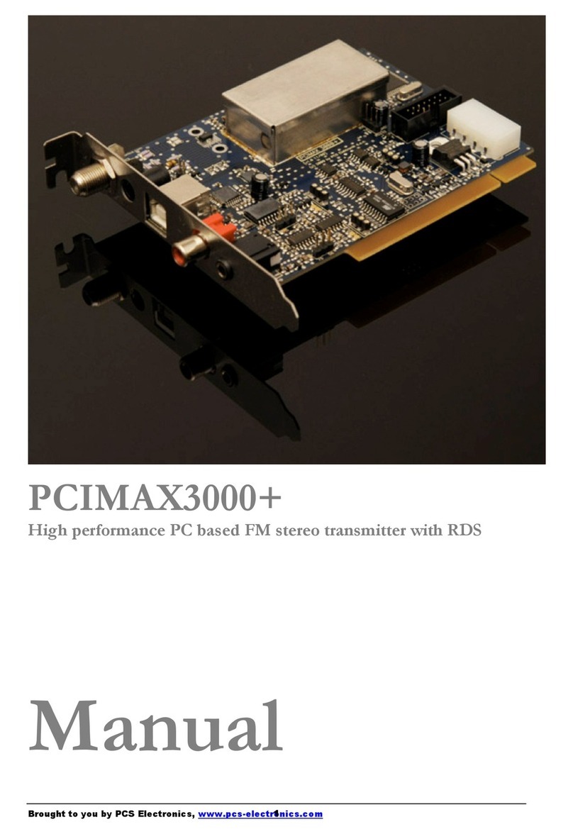
PCS Cybermax FM+ 15W DSP User manual

Brought to you by PCS Electronics, www.pcs-electronics.com
CyberMax FM+ 15W DSP/RDS
High performance FM radio broadcas ing exci er
Manual

Brought to you by PCS Electronics, www.pcs-electronics.com
I M P O R T N T N O T E
- Upon receiving your order inspect the packaging material and unit for apparent damage.
ny damage should be reported immediately so we can make a claim with the shipping
company. Take photos, if you can, they can be used as a proof.
- Mains cable is typically not included with our mains power supplies and units. Since these
cables vary from country to country and we had trouble finding the exact type we decided
against including them, especially since finding them is so easy and cheap locally. They
can be obtained in any radio/computer/hardware shop at the cost of about 1 US$. It is the
type used in your PC for mains power.
- Study local regulations and ensure you are operating in compliance.
- Do not open the unit or attempt service yourself. Deadly mains voltage is present inside.
There are also high RF voltage points that can cause burns and discomfort if touched.
- Finally, never ever operate any transmitter or amplifier without a properly tuned antenna!

Brought to you by PCS Electronics, www.pcs-electronics.com
Table of Contents
Introducing CYBERMAX FM+ series of transmitters ................ 5
What makes this FM transmitter series so great? ........................... 5
General features: ............................................................................ 5
Technical specifications: ................................................................. 6
Thank you for purchasing CyberMaxFM+ transmitter ..................... 6
Front and back panel layout ..................................................... 7
What’s inside the box? ............................................................. 8
FM Exciter board............................................................................. 8
Stereo encoder board ..................................................................... 1
RDS encoder board ........................................................................ 1
Where can I find more info?............................................................ 1
Before you start........................................................................ 2
Antenna........................................................................................... 2
So what is this swr (vswr) everyone talks about?............................ 3
Coaxial cable .................................................................................. 3
Mains power supply and mains power cable................................... 3
Audio source with mixer, microphone etc........................................ 3
Wiring everything together ....................................................... 4
Wiring things up and first power-up................................................. 4
Using the CyberMaxFM+ series transmitter ............................. 5
Lcd control module menu system: Power and DSP functions......... 5
Changing frequency........................................................................ 5
<RF POWER> ................................................................................ 5
<STEREO MODE> ......................................................................... 5
<VIEW SELECT>............................................................................ 6
<TREBLE> and <BASS> ................................................................ 6
Compressor Settings....................................................................... 6
<LCD CONTRAST> ........................................................................ 7
Left and right channel volume (only with DSP stereo encoders)..... 7
<PLL STEP> ................................................................................... 8
<RF EQ>......................................................................................... 8

Brought to you by PCS Electronics, www.pcs-electronics.com
<FIRMWARE VER> ........................................................................ 8
<PWR/SWR METER>..................................................................... 8
<TEMP ALARM> ............................................................................ 8
<SWR ALARM> .............................................................................. 8
<BAND SELECT>........................................................................... 8
<RF AMP CONTROL>.................................................................... 9
Troubleshooting .............................................................................. 9
Appendix A: DIY antenna and improvement tips .................... 11
Simple GP antenna design ........................................................... 11
Some more improvement tips ....................................................... 11
Appendix B: General tips for setting up transmitters............... 12
Typical FM transmitter setups ....................................................... 12
Typical FM broadcasting antenna setups...................................... 13
Wiring antennas in multi-bay configurations.................................. 14
Appendix C – Attaching external stereo processor................. 15
Appendix D – Using and setting up the RDS encoder ............ 16
Software installation...................................................................... 16
Configuring RDS communications ports ....................................... 17
Installing USB driver (USB IO board)............................................ 17
Configuring USB driver ................................................................. 17
Using windows control program .................................................... 18
Appendix E – Warranty and legal info ...................................... 2
Important notice! ............................................................................. 2
Warranty and servicing! .................................................................. 2
Legal info ........................................................................................ 2
Limitation of liability......................................................................... 2
Also available from www.pcs-electronics.com ................................ 3
Revisions and errata ................................................................ 4
Index ........................................................................................ 5

Introducing CYBERM X FM+ series of transmitters
Our series of rack mounted stereo FM radio transmitters
with optional RDS and DSP processing
his manual covers our 15W CYBERMAX FM+ transmitters. Even though the design o these units evolved
radically over the years transmitters rom this series remain one o our best selling items. Today our customers
still enjoy the incredible price/per ormance ratio and more reliability, power and eatures than ever be ore. In
this manual you will ind all o its little exciting secrets.
What makes this FM transmitter series so great?
Besides o ering all the standard basic eatures these units also display a number o use ul parameters on the LCD display:
transmitted power, re lected power, exciter temperature, exciter voltage, requency, audio modulation level, ampli ier voltage
and ampli ier temperature. They are available in mono (MPX input) and stereo (with regular or DSP stereo encoder). RDS
(Radio Data System) is also available. O course this unit is completely no-tune and works either rom car battery (12-15V)
or with our universal mains power supply which works worldwide.
Com ortably sized 1H 19" rack enclosure o ers easy access to all internal components and assures good ventilation. A
number o protection circuits helps prevent disasters. Temperature and SWR are monitored by on-board computer and
alarm threshold can be set via LCD module. Hardware old back SWR protection is also built-in as a backup. Unit is
rugged and made or 24/7/365 operation. In our opinion the best quality/price ratio possible.
General features:
- True wideband no-tune operation (no tuning required to make it work, just set the requency and antenna)
- Covering entire FM broadcasting band with clean signal and great sounding audio
- Built-in SWR and TEMP protection or peace o mind
- High power (12-15W typ, 20W max) rom either mains power or battery (12-15V), per ect or mobile or solar powered
installations.
- Digital output power adjustment (with up/down keys)
- Both DSP and analog models have extremely sharp audio ilters
- DSP model o ers complete control over audio parameters via LCD menu system
- Optional high-per ormance RDS encoder with scrolling PS and many other eatures.
Chapter
1
T

Brought to you by PCS Electronics, www.pcs-electronics.com
Technical specifications:
RF sec ion:
- Frequency range: 87.5-108MHz and 76-90MHz in Japanese band mode (reduced output power below 87.5MHz)
- RF Output Power: 0 to 15 Watts (20W max, 12-15W typ, digitally adjustable with UP/DOWN keys)
- Output connector: BNC (N and SO239 adapters reely available)
- Output Impedance: 50 Ohms
- PLL steps: 5KHz (10/25/50/100/200KHz adjustable via lcd)
- Frequency stability: +/- 20Hz
- Spurious/Harmonic rejection: Harmonics: >50dB, Spurious: -90dB
- RF output ruggedness: SWR protection, TEMP protection, reduced power with LCD warning and RED LED
- Quartz locked PLL requency control, ultra stable & clean output
- S/N ratio: >90 dB
- No expensive test equipment required to setup
Audio sec ion:
- Audio per ormance: Less than 0.2% distortion, 20Hz-75KHz
- Pre-emphasis, 50uS, 75uS or none selectable
- Audio Input Level: 0 dB
- Stereo separation: > 50dB
- Audio low pass ilter with 19KHz notch ilter: Yes, all models
- Audio input impedance: 10Kohms balanced, 1Kohms unbalanced
- Limiter: Yes, all models
- Pre-emphasis: Yes, precision 50uS, 75uS or none or all models
- DSP: Yes, in DSP models
General:
- Power supply: 11-15V/2.5A or car battery (does not require 15V or ull power)
- Power jack: 2.1mm power socket, center (+), polarity protection (diode + use)
- LCD display shows: Power, re lected power, requency, temperature, supply voltage, modulation level and uptime counter
- Optional AC mains power: 110-240V 50/60Hz universal, works anywhere on this planet
- Ambient temperature: -5° to +45°C
- External dimensions ( W x D x H ) 19" x depth (130mm) x height 1HE (44mm)
- Weight 1kg
Thank you for purchasing CyberMaxFM+ transmitter
We hope you will enjoy it as much as we do and i you do remember to tell your riends and colleagues about it. Please eel
ree to leave your comments at our website or post your experience in our orum. And i you encounter a problem please
let us know so that we may improve our products, o er advice and suggestion. From all o us we wish you happy
broadcasting!
Your PCS Electronics team

Brought to you by PCS Electronics, www.pcs-electronics.com
Front and back panel layout
Fig. 1: Front panel
Reference Func ion
1 Three push buttons, the UP, DOWN and MENU keys.
2 LCD display that lets you control the unit and monitor various parameters.
3 The green led. Green signals power is ON.
4 Red error led. Turns on while VCO is tuning into selected requency and in case o SWR or TEMP error.
5 Power switch in the middle o the panel is actually a standby switch. To really disconnect the unit rom
mains power use the main switch at the back.
Fig. 2: Back panel
Reference Func ion
1 Power jack, center is positive. 12-15V DC, 2.5A
2 Fuse, F3A/250V
3 Ventilation aperture
4 Antenna connector, BNC. Do not operate without antenna.
5 BNC connectors or MPXin, MPXout and 19KHz pilot.
6 RS232/USB or controlling your RDS encoder.
7 Audio inputs, RCA jacks or le t and right channel
8 STEREO mode indicator.
9, 10 Balanced audio inputs, le t and right channel XLR (Canon)
Chapter
2

Brought to you by PCS Electronics, www.pcs-electronics.com
What’s inside the box?
CyberMaxFM+ 15W units are available in several con igurations. Exact internal con iguration depends on the particular
model. Since we sometimes change con igurations it is best to check our website or latest in ormation. Below are the basic
building blocks o the exciter. Note that the RDS encoder is optional and only available in models with RDS capability.
Similarly DSP encoder is only available in DSP capable models. We are now going to have a look at these building blocks
one at a time:
Fig. 3: Block diagram o the CyberMaxFM+ transmitter
FM Exciter board
15W CyberMaxFM+ units utilize our MAX PRO series FM exciters
Fig. 4: MAXPRO3000+ FM exciter board layout
Chapter
3
Ref Func ion
A On-OFF switch
E Pre-emphasis. For mono operation set to OFF
G Modulation level
H Audio input
R 6-pin header to the stereo encoder
P 14-pin header to the LCD module
J LCD power meter accuracy
M FAN power pads
S Fuse, F3A250
T Power supply, (+) center, 12-15V/3A stabilized
W Antenna connector, BNC

Stereo encoder board
15W CyberMaxFM+ units utilize our SE5000 DSP+ and SE3000 AN+ stereo encoders
Fig. 5: SE5000 DSP+ stereo encoder board layout
RDS encoder board
15W CyberMaxFM+ units utilize our RDS MAX 4000+ and RDSMAX4000+ mini RDS encoders
Fig. 6: RDSMAX4000+ rds encoder board layout
Where can I find more info?
Separate extensive manuals or all o the built-in components are available on our website. We have a section in our orum
dedicated to all o the manuals and you can discuss each o the manuals with other orum members here:
http://www.pcs-electronics.com/phpBB2/view orum.php? =33
Ref Func ion
J1-2 Audio Inputs
J3-4 Pre-emphasis selection
J7 MPX out, going to FM exciter audio input
J10 Mode select, don’t install in this con iguration
J11 Maxlink 6-pin cable going to MAX PRO 3000+
exciter
J12 Install to reduce pilot level slightly
J14 Stereo/mono selection, do not install jumper here
Ref Func ion
P1 RDS level
P2 RDS carrier phase relationship to stereo pilot
J11-13 Baud speed selection, leave at de ault
CLK RDS clock led, should blink at around 1Hz
57KHz
PLL lock led, should be o in stereo mode

Brought to you by PCS Electronics, www.pcs-electronics.com
Before you start
It is recommended that you read this section be ore you power your unit up or the irst time. Let us clear up some basics
you should know about. You will also ind some use ul tips in our guides and orum at http://www.pcs-electronics.com.
Here is what you need to get your TV transmitter on the air:
ntenna
Pre erred type o antenna is a ected by several actors, but mostly by desired radiation pattern, space available and your
budget. I you are located in the middle o the area you want to cover you'll need an omni-directional antenna which
transmits equally in all directions. I you are located at the edge o your desired coverage area you can beam the signal into
the target area with a directional antenna. Directional antennas are also practical or point-to-point communications.
Another thing to consider is that directional antennas usually have much higher gain than omni-directional antennas since
the power which is radiated in all directions with omni antenna is concentrated mainly into one direction with directional
antenna. Antennas with more gain thus have narrower beam. A compromise is usually made depending on budget and
space available, higher gain antennas are o ten bigger and o ten more expensive.
Once you’ve chosen and installed your antenna there is another thing to consider. You can read more about it in the next
section (So what is this SWR everyone talks about). Be ore powering up your transmitter on the air you should tune your
antenna to get minimal SWR. This is typically done by adjusting the position o the antenna and any adjustable pieces. Aim
or 2:1 or less. Use low power into the antenna when tuning it up and making adjustments. I you were using ull power and
a bit o the antenna came o in your hand the VSWR could be so bad as to blow the inal transistor. For the same reason
check the DC continuity o the antenna with an ohmmeter be ore plugging it in, to be sure it's what it's meant to be, either a
short circuit or an open one, depending on the antenna type. For instructions regarding construction o antennas please see
our website: http://www.pcs-electronics.com (guides section - antennas).
Antenna is a crucial part o the system so take special care. It is usually a good idea to place antenna away rom your
transmitter, power supply and audio system. Also any transmitter should be in a metal case which shields circuitry rom the
radiation o the antenna. I you cannot meet these requirements, you could experience eedback and other RF problems. We
cannot guarantee proper operation o any transmitter/ampli ier unless suitable antenna system is used and transmitters are in
ventilated metal enclosure! This applies to any transmitter. Interestingly, strong RF ield can make CD players and other
digital devices go bezerk. Try placing antenna next to yours and see what happens. Most o the modern audio gear is not RF
shielded – reducing costs is un ortunately the mantra today. This is why keeping antenna away rom audio gear is a good
idea, too.
I you are going to place your antenna outside, on your roo , please take care o the grounding. This should be done to
prevent lightning hazard and should be done by a company specializing in lightning protection. You can read more about
lightning protection in the book recommended below or many o the websites (Google up “lightning protection ham radio”
or example) .
I hope this basic introduction will not scare you too much, it should be su icient or the time being although we encourage
you to explore this exciting subject urther with the help o a book such as the ARRL Antenna Book:
http://www.amazon.com/exec/obidos/ASIN/0872598047/mightyspiraterad
Chapter
4

Brought to you by PCS Electronics, www.pcs-electronics.com
So what is this swr (vswr) everyone talks about?
SWR is a measure o how well two devices are impedance matched to each other. Typical radio/TV transmission equipment
is designed or 50 ohm load impedance, so we usually use 50 ohm cables and build or buy antennas that are speci ied or 50
ohm. While most cables have lat impedance over requency (they measure 50 ohm at all requencies you are likely to use)
the same is not true o the antennas.
A 1.0:1 VSWR is a per ect match. That means the load impedance is exactly 50 ohms. A 2.0:1 VSWR is obtained when the
load impedance is either 25 ohms or 100 ohms.
Because most transmitters will deliver ull power with a load VSWR o up to 2.0:1, this value is usually considered the limit
or acceptable operation. Many pre er to keep their VSWR below that however, but or all practical purposes, it is
unnecessary to spend time or money trying to get much below a VSWR o 1.5:1. The bene its will be hard to measure and
even harder to notice.
On the other hand, coaxial cable losses increase rapidly, or a given requency o operation, when the antenna VSWR
exceeds 2.0:1. This can even, in some extreme cases, result in the coaxial cable burning, even when running 100 W. Using a
higher grade o cable will de initely improve things, but even high quality coaxial cable becomes very lossy when VSWR
exceeds 3.0:1 at higher HF requencies (or VHF and higher).
Coaxial cable
Coaxial cable is an electrical cable consisting o a round, insulated conducting wire surrounded by a round, conducting
sheath, usually surrounded by a inal insulating layer. The cable is designed to carry a high- requency or broadband signal,
usually at radio requencies. Coaxial Cabling is a two conductor closed transmission medium that is o ten used or the
transmission o RF energy. It yields excellent per ormance at high requencies and superior EMI control/shielding when
compared to other types o copper cabling. Coaxial cabling is commonly ound in broadcast and networking systems. Most
coaxial cables have a characteristic impedance o either 50 or 75 ohms. The RF industry uses standard type-names or coaxial
cables. The U.S military uses the RG-# or RG-#/U ormat (probably or "radio grade, universal", but other interpretations
exist).
The common RG-58 rom Radio Shack is NOT the best you can do and can eat a lot o your e ective power out! Use it
only or short runs. BELDEN makes terri ic coaxial cable in various qualities and with very low loss (measured in
dB’s…decibels). 3 dB loss = 1/4 o your signal strength - either lost or gained. Watch out or the correct impedance; RG58,
RG213, H-500 and H-155 have 50 Ohms, RG-59 and RG-6 have 75 Ohms. Most antennas and transmitters including ours
are 50 ohm. Check our website or good coax. Don't buy more than you need to make the long run to your antenna and
don't make up a ew "jumpers" to go between your exciter, VSWR meter and your antenna as all you'll do is create higher
SWR and more line losses. H-155 or H500 are good choices! RG-142 with Te lon is recommended or wiring inside
cabinets, or baluns, Wilkinson couplers and everywhere where resistance to heat is required as insulation won’t melt during
soldering or operation.
Mains power supply and mains power cable
Do not underestimate the importance o mains power supply, despite abundance o all kinds o cheap units available today
they un ortunately do not always meet requirements. What you need is a well stabilized DC 15V mains power supply that
can supply at least 2 amps o continuous current without overheating, introducing buzzing, dropping the voltage down to
12V or lower (a classic case) or acting up in other way. Whenever in doubt please buy our mains power supply. One inal
note, i you use less than 15V this e ectively lowers your output power. The lower the supply voltage the lower the power.
I you ordered and received our mains power supply (which is recommended) you’ll notice the mains cable is not included,
but can be obtained in any radio/computer/hardware shop at the cost o about 1 US$. It is the type used in your PC or
mains power. Since these cables vary rom country to country and we had trouble getting the exact type locally we decided
against including them, especially since inding them is so easy locally.
udio source with mixer, microphone etc
You need some kind o audio source to drive your transmitter. This will typically be either a computer (just plug the cable
into your sound card outputs, a mixer and a variety o audio sources, such as a microphone, CD player, DAT player, tape
deck, gramophone, MP3 player etc.

Brought to you by PCS Electronics, www.pcs-electronics.com
Wiring everything together
Wiring things up and first power-up
Wiring the CyberMaxFM+ is easy, just make sure you read the previous chapter irst and setup antenna and coaxial cable
correctly. Than proceed with the ollowing:
- Erect antenna tower and install antenna securely. Make sure your antenna is well away rom any metal objects. Ensure your
antenna tower is grounded securely.
- Connect one end o your 50ohm coaxial cable to the antenna. I you have SWR analyzer you can now veri y SWR o your
antenna. I your antenna is already tuned connect the other end o coaxial cable to the antenna connector (BNC) at the back
o the transmitter. I you have SWR/POWER meter, you can wire that one inline between antenna and transmitter as well.
Make sure the SWR meter supports the requency band required (87-108MHz). Ensure all connectors are irmly secured and
antenna is mounted securely.
- While making sure power switch is o connect mains power cable into the mains power supply and connect mains power
supply into the back o the transmitter.
- Inspect all cables quickly again and make sure everything is secure.
- Turn on a radio receiver and set it to your intended transmitter requency.
- Flip the POWER switch and wait or the unit to turn on. Enter the menu system by pressing the bottom key (Menu)
repeatedly and look or the <RF power> menu item. Now set desired output power with the UP/DOWN keys. For tuning
and testing use around 25-50% o ull power. Press Menu again to exit back to main display. Now you can use the
UP/DOWN keys to set the desired requency o operation. Wait a ew seconds or the red LED diode to turn o . Your
radio should now mute since you did not connect any audio sources yet.
- Observe SWR and output power. I everything seems ok enter <RF power> menu on your ampli ier again. Increase power
to ull.
- You can now connect audio sources o choice and veri y audio per ormance. You should not sound louder than other
stations, in act unless you have an expensive high per ormance so tware or hardware sound processor you should sound
quieter than other stations.
Chapter
5

Brought to you by PCS Electronics, www.pcs-electronics.com
Using the CyberMaxFM+ series transmitter
Basically there are three push-buttons available or the menu system; UP, DOWN and MENU. By pushing UP or
DOWN you get a shi t o requency in corresponding direction. Hold any o these keys or a ew seconds and the jumps
will increase to 500 KHz. The new requency is saved automatically. The third button (MENU) gives you an option to
select and setup many o the options and DSP unctions o this unit.
Lcd control module menu system: Power and DSP functions
The UP and DOWN keys are used to change parameter values. In normal mode the LCD simply shows the requency and
power or whatever view you select. Menu key can be used to enter the menu mode, repeatedly pressing this key brings up
the ollowing menus: <RF POWER>, <STEREO MODE>, <VIEW SELECT>, <TREBLE>, <BASS>,
<COMPRESSION>, <THRESHOLD>, <ATTACK>, <DECAY>, <INTEGRATION>, <LCD CONTRAST>,
<RIGHT CH VOL>, <LEFT CH VOL>, <PLL STEP>, <RF EQ>, <FIRMWARE VER>, <PWR/SWR METER>,
<TEMP ALARM>, <SWR ALARM>, <BAND SELECT>, and <RF AMP CONTROL>. Pressing the UP or DOWN
key selects the desired parameter and allows you to modi y its value. Another press on the MENU key and you’re back to
the normal mode. Note that all these settings except power and requency are already set as they should be so changing them
should not be necessary and is not recommended.
Changing frequency
Simply press the UP/DOWN button to change requency. Depending on PLL STEP setting your requency will go down in
5/10/25/50/100/200KHz steps. I you keep pressing a key or a while the PLL STEP switches to ast tuning mode and
jumps in 500KHz steps.
No e: Frequency changes also when you select a view type which does not show requency, such as UPTIME.
<RF POWER>
This setting allows you to set output power. Select desired power with the UP/DOWN keys and press MENU key to exit
the menu system and return to normal operation. Selected power is displayed on the LCD as a line o bars. Think o this
setting as an accelerator (gas) pedal in your car. Think o the power in watts that is shown on the LCD as the speed meter in
your car. Depending on the road going uphill or downhill speed meter will show di erent values even i your accelerator
pedal is ixed in the same position. I you go downhill your speed will be greater with same amount o gas pedal. Likewise
here your supply voltage can a ect the actual output power slightly.
<STEREO MODE>
You can set your transmitter to MONO or STEREO here.
Chapter
6

Brought to you by PCS Electronics, www.pcs-electronics.com
<VIEW SELECT>
CyberMaxFM+ is capable o displaying a number o various parameters. Since the LCD real-estate is limited to 2x16
characters we prepared a number o pre-programmed views that only show a selected number o parameters. At the time o
writing these views were available:
- [Freq+Mode+Pwr] – This view shows requency, mono/stereo mode and output power
- [Fr+Mode+Te+Ue] – This view shows requency, mono/stereo mode, exciter temperature and exciter supply voltage
- [Po+Pr+Uamp+Ta] – This view shows output power, re lected power, ampli ier supply voltage and ampli ier temperature
(i used)
- [Audio Level] – This view shows audio level bar graph. For this to work you the W solder bridge on the LCD module
needs to be closed-soldered.
- [Uptime D:H:M] – This view shows how long the transmitter has been operating without mains power going out. It is
sometimes use ul in diagnosing mains power ailures.
- [Auto Scroll]D – This is the de ault view, it shows each o the above listed views or a short while and than moves on to
the next in an endless loop. This way you can see all the relevant parameters without having to go through the menu system
to change the view type, You just have to wait a ew seconds or the view to change.
<TREBLE> and <B SS>
This option allows you to set the amount o TREBLE and BASS in your audio. Recommended values are marked with (D).
Fig. 7: Setting treble
Compressor Settings
A number o MENU settings control the operation o the compressor. Lets assume that the audio signal enters the
transmitter at some low level. Compressor does nothing to the signal until at one point as the input signal increases the signal
reaches the compression threshold. Digital signal processor starts compressing the signal beyond that point. The higher the
compression ratio the higher the compression. For example, compression ratio o 1:
∞
would in e ect be a limiter.
Fig. 8: Explanation o the compressor settings

Brought to you by PCS Electronics, www.pcs-electronics.com
Fig. 9: Setting the compression level
Fig. 10: Setting the compression threshold
Fig. 11: Setting the attack time, this is the time between the input signal and the actual response o the compressor
Fig. 12: Setting the decay time, this is the time the compressor needs to respond a ter the input signal alls back to normal level (below threshold).
Fig. 13: Setting the integration interval, this is the time the DSP evaluates the signal to establish whether it should respond or not
Integration interval determines the energy needed to trip the compressor. In simple words; it determines how long the audio
needs to be loud or the compressor to respond by reducing the gain. This is not to be con used with attack time. Attack
time o 50ms means the compressor will respond in 50ms a ter the signal spike is detected, regardless o duration o that
spike, even i it is just a very short event. With longer integration interval, on the other hand, compressor only responds i a
long spike or a substantial number o spikes is detected (meaning more signal energy).
<LCD CONTR ST>
Select or the best visibility. Contrast is slightly a ected by ambient temperature and you can adapt it to your needs here.
Fig. 14: Changing contrast
Left and right channel volume (only with DSP stereo encoders)
This option allows you to precisely adjust the input sensitivity o both audio channels. This is very use ul when your audio source has either too
high or too low output level.

Brought to you by PCS Electronics, www.pcs-electronics.com
Fig. 15: Changing right input channel gain
<PLL STEP>
Frequency can normally be adjusted in smallest steps o 5KHz or larger steps o 10KHZ, 25KHz, 50KHz or 100KHz. We
recommend you to select 100KHz as this lets you change requency ast and there is rarely need or ine tuning. However,
you can enter this menu and select a PLL step o 5KHz or example and take advantage o these small steps.
<RF EQ>
Just leave this setting at de ault. It is better suited or our 100-1000W units. It is a new setting that lets you control how your
transmitter rolls o at the band edges. Several settings are available and are represented by a graphic. De ault setting tries to
provide the same amount o power across the whole band.
Another setting gives a slight power boost at the band edges around 88 and 108MHz helping latten-out the requency
response o many RF ampli iers which tend to have lower output power and gain at the band edges.
There are additional two settings, one o these gives more power at the top o the band around 108MHz and the other does
the opposite, providing more gain at the bottom o the band around 88MHz. These our settings should cover any situation
you are likely to encounter, whatever your ampli ier’s attitude might be.
<FIRMW RE VER>
This option allows you to display current LCD module irmware version. At the time o writing irmware version was
[MP3K+ V2.0 7/09]
Fig. 16: Firmware version
<PWR/SWR METER>
This is how you tell the exciter that you are going to use external directional coupler and power ampli ier. By selecting
“External” the exciter assumes that you’ve set the J5 jumpers into external position and attached external directional couplers
or our ControlMini2 board. You can read more about ControlMini2 in the MAX PRO 3000+ manual.
<TEMP L RM>
You can set the sensitivity o temperature alarm here. We recommend you set these to 70-80 degrees Celsius. A properly
installed unit with a tiny an will typically run at 55 degrees C at maximum output power. This alarm applies to externally
sensed temperature (ControlMini2), i you are using external PWR/SWR METER.
<SWR L RM>
You can set the sensitivity o so tware driven SWR alarm here.
<B ND SELECT>
CyberMaxFM+ supports three bands:

Brought to you by PCS Electronics, www.pcs-electronics.com
[87.5-108MHz]D – This is de ault band, used in most o the world. CyberMaxFM+ works per ectly across the entire band.
[76-90MHz/Japan] – This band was developed speci ically or Japan. You can experience slightly lower output power below
87.5MHz. Also iltering is a bit less aggressive below regular FM band (87.5MHz).
[44-54MHz] – While the PLL and driver ully support this requency band, you will have to change coils in the output
matching network and output ilter to obtain usable RF signal out o the exciter. We have provided this band or the wireless
links in the lower VHF band (around 50MHz). This last option is only or people who know how to use it so please don’t
use this setting unless you understand it.
<RF MP CONTROL>
This menu option lets you choose how the MAX PRO 3000+ controls the ampli ier. It o ers three options, described in the
manual or the MAX PRO 3000+. Please leave this setting at de ault value (D) No ampli ier as it has no unction in 15W
exciters since they don’t have additional external ampli iers.
- [No ampli ier]D – De ault option, you will not be using an ampli ier
- [Controlmini1] – Basically mode A or the system described in appendix I
- [ControlMini2] – Basically mode B or the system described in appendix I
Troubleshooting
We hope you’ll never get to this step. We all know bad things happen but do not despair! Cybermax FM+ is protected with a
use, SWR and TEMP protection. Fuse is the irst thing to check. Make sure your coaxial cable leading to the transmitter or
antenna is not shorted or open. Next check the troubleshooting table on the next page. I you have problems you cannot
solve yoursel , please see our website or contact in ormation and support resources in our orum.
Fig 17: So, do you think you can handle it? We think you sure can!

Brought to you by PCS Electronics, www.pcs-electronics.com
PROBLEM DESCRIPTION POSSIBLE SOLUTIONS
LCD display keeps showing
TEMP/SWR error warning
1. Unit is probably over-heating or your antenna is aulty. Let the unit cool o and
ensure proper cooling in the uture. Perhaps you adjusted TEMP ALARM too low,
set it slightly higher.
2. It is very likely that your antenna is not working correctly, check cable and check
SWR
Red LED constantly on 1. High SWR. Check SWR and adjust antenna, i needed
2. Wait a ew seconds. Unit turns this LED on when changing requency just or a
ew seconds until VCO stabilizes. This is normal behavior also at power-up.
Audio too quiet 1. Open the top lid and open the modulation trimmer on MAX PRO 30000+
exciter board a little bit.
2. Increase level on your audio source a little bit, start using so tware or hardware
compressor
Audio too loud Open the top lid and close the modulation trimmer on MAX PRO 30000+ exciter
board a little bit.
Audio without any treble Set pre-emphasis to either 50uS or 75uS. I you’re using stereo model, enable pre-
emphasis there (see manual or stereo encoder module , SE5000 or SE3000).
Unit blows uses and draws
excessive current
You have managed the impossible: You have burned the output transistor. You've
probably tried to squeeze out more output power by using higher supply voltage
above 15V or even changing the bias current. It is time to order a replacement inal
transistor and get the soldering iron. Next time think twice about doing these things.
Power supply is blinking Probably the same thing as above. Blinking power supply means its protection is
shutting it o and back on, probably due to excessive current draw caused by
burned inal.
Audio distortion on high peaks,
or example on “s” sound.
Your audio input level is slightly too high, reduce input audio level slightly at your
audio source. Use some kind o compressor to remove over-modulation peaks.
There is HUM in audio - Move antenna as ar away rom the transmitter and audio gear as possible
- Use balanced audio inputs (XLR audio connectors) rather than RCA
- Make sure SWR is low
- Keep audio cables short and away rom antenna and RF coaxial cable
- Form a coil rom coaxial cable going to the antenna, make a ew turns. This stops
RF currents that might be lowing on the outer braid o the coaxial cable. This
usually happens when you connect unbalanced cable to balanced antenna without
proper BALUN (balanced-unbalanced converter) resulting in coaxial cable
becoming part o the antenna and radiating RF energy as well…causing hum.
Loss o settings a ter power o Check irmware version and contact our support or upgrade options.
Output power less than expected We set our transmitters to work best with our 15V power supply. I you intend to
use 11-12V you can increase bias current a little bit, this is done with the blue
trimmer next to the output transistor.
Output power less than expected I unit is overheating it will start reducing output power, make sure it is su iciently
cooled!
Output power less than expected Units can have slightly reduced output power at the band edges around 88 and 108
MHz. You can improve per ormance by tweaking coils in ilter a little bit.

Brought to you by PCS Electronics, www.pcs-electronics.com
ppendix : DIY antenna and improvement tips
Simple GP antenna design
You can build an inexpensive 1/4 wave antenna rom 1 so-239 chassis mount r connector and 5 - 3' bronze welding rods,
cut to the proper length. Here is how it looks:
Fig. 18: »Do it yourself« GP antenna
For other antenna designs check our web site here: http://www.pcs-electronics.com/guide_antenna.php
Some more improvement tips
Think about purchasing SWR meter to tune and align your antenna. A good antenna system is extremely important and can
make up or a lot o power. For a suitable SWR meter check:
http://www.pcs-electronics.com/cn101l-daiwa-power-meter-p-347.html
I you can’t get much range with your homebrew antenna, have a look at these:
http://www.pcs-electronics.com/antennas-c-38.html
Still not enough range? Well, how about a 750W ampli ier?
http://www.pcs-electronics.com/750w-digital-ampli ier-19inch-rack-p-1295.html
ppendix
I you have a SWR meter,
leave a bit longer radiator
and adjust it later by
cutting to achieve
minimum SWR.
Most designs on the web don't compensate or the act
that GP antennas are not wideband antennas. Here is a
Freq/element length chart or this simple GP antenna, all
element lengths are in millimeters:
Frequency Radiator - B Radials - A
108MHZ 660mm 693mm
104MHz 684mm 720mm
100MHz 713mm 749mm
90MHz 792mm 819mm

Brought to you by PCS Electronics, www.pcs-electronics.com
ppendix B: General tips for setting up transmitters
Typical FM transmitter setups
Below are several o the typical broadcasting systems that can be encountered worldwide.
Fig. 19: Typical broadcasting systems
Lets look at sys em A irst. It consists o audio source (mixer, microphones, CD players and a PC), FM exciter with
integrated RDS and stereo encoder (such as our CyberMaxFM+ units rom 15W-300W) and antenna. Note antenna in this
system is located in the same location as the transmitter and studio, typically it would be placed on a small tower or a pole at
the top o the building with studio. Disadvantage o this system is that you have to keep studio, transmitter and antenna
close. Now you usually can’t place studio on the top o a mountain or practical reasons so this limits your range. This is a
typical small community radio with output powers o up to 300-500W.
Sys em B is very similar to system A, but operators have decided to add an additional ampli ier to boost the range. Such
stations can go into kilowatts, but they are starting to hit another speed limit. Since the studio is typically located in a town,
high RF powers aren’t desirable due to inter erence with other services and sa ety regulations. So range is still limited
compared to system C stations.
Sys em C is radically di erent in one respect. Antenna and transmitter are no longer located at the same place with the
studio. To accomplish this the two audio channels are irst combined with stereo processor. Resulting MPX signal is than
passed to the STL wireless link transmitter (STL=Studio Transmitter Link). Up in the mountains is a STL wireless link
receiver that receives the signal rom the studio and passes I to the exciter. In this case exciter does not need to be stereo
anymore since composite MPX signal is passed to its MPX input (all mono transmitters have this input). Such exciters can
than optionally drive big ampli iers with powers going into tens o KW with maximum range.
You can check our ampli iers here: http://www.pcs-electronics.com/ m-ampli iers-c-41.html
You can check our wireless STL links here: http://www.pcs-electronics.com/wireless-audio-links-c-42.html
ppendix
B
This manual suits for next models
1
Table of contents
Other PCS Transmitter manuals